Page is loading ...

2012.09
Super Speed Dome
x37 PTZ Outdoor All in One
Dome Camera
Before installing and using the camera, please read this manual carefully.
Be sure to keep it handy for future reference.
User’s Manual

Safety Information
2
This symbol indicates that dangerous voltage
consisting a risk of electric shock is present within
this unit.
Warning Precaution
This exclamation point symbol is intended to alert the
user to the presence of important operating and
maintenance (servicing) instructions in the literature
accompanying the appliance.
TO REDUCE THE RISK OF ELECTRIC SHOCK, DO NOT REMOVE COVER (OR BACK) NO USER SERVICEABLE
PARTS INSIDE. REFER SERVICING TO QUALIFIED SERVICE PERSONNEL.
CAUTION
:
CAUTION
RISK OF ELECTRIC SHOCK.
DO NOT OPEN.
To prevent damage which may result in fire or electric shock
hazard, do not expose this appliance to rain or moisture.
Be sure to use only the standard adapter that is specified in
the specification sheet. Using any other adapter could cause
fire, electrical shock, or damage to the product.
Incorrectly connecting the power supply or replacing battery
may cause explosion, fire, electric shock, or damage to the
product.
Do not connect multiple cameras to a single adapter.
Exceeding the capacity may cause excessive heat generation
or fire.
Securely plug the power cord into the power receptacle.
Insecure connection may cause fire.
When installing the camera, fasten it securely and firmly.
A falling camera may cause personal injury.
Do not place conductive objects (e.g. screw drivers, coins,
metal items, etc.) or containers filled with water on top of
the camera. Doing so may cause personal injury due to fire,
electric shock, or falling objects.
Do not install the unit in humid, dusty, or sooty locations.
Doing so may cause fire or electric shock.
If any unusual smells or smoke come from the unit, stop
using the product. Immediately disconnect the power sorce
and contact the service center. Continued use in such a
condition may cause fire or electric shock.
If this product fails to operate normally, contact the nearest
service center. Never disassemble or modify this product in
any way.
When cleaning, do not spray water directly onto parts of the
product. Doing so may cause fire or electric shock.
WARNING
WARNING
1.
2.
3.
4.
5.
6.
7.
8.
9.
10.
Precaution
Operating
• Before using, make sure power supply and all other parts are
properly connected.
• While operating, if any abnormal condition or malfunction
is observed, stop using the camera immediately and contact
your dealer.
Handling
• Do not disassemble or tamper with parts inside the camera.
• Do not drop the camera or subject it to shock or vibration as
this can damage the camera.
• Clean the clear dome cover with extra care. Scratches and
dust can ruin the quality of the camera image.
Installation and Storage
• Do not install the camera in areas of extreme temperature,
exceeding the allowed range.
• Avoid installing in humid or dusty environments.
• Avoid installing in places where radiation is present.
• Avoid installing in places where there are strong magnetic
elds and electric signals.
• Avoid installing in places where the camera would be subject
to strong vibrations.
• Never expose the camera to rain or water.

3
1. Read these instructions. - All these safety and operating instructions should be read before the product is
installed or operated.
2. Keep these instructions. - The safety, operating and use instructions should be retained for future reference.
3. Heed all warnings. - All warnings on the product and in the operating instructions should be adhered to.
4. Follow all instructions. - All operating and use instructions should be followed.
5. Do not use this device near water. - For example: near a bath tub, wash bowl, kitchen sink, laundry tub, in a wet
basement; near a swimming pool; etc.
6. Clean only with dry cloth. - Unplug this product from the wall outlet before cleaning. Do not use liquid cleaners.
7. Do not block any ventilation openings. Install in accordance with the manufacturer’s instructions. - Slots and
openings in the cabinet are provided for ventilation, to ensure reliable operation of the product, and to protect it
from over-heating. The openings should never be blocked by placing the product on bed, sofa, rug or other similar
surface. This product should not be placed in a built-in installation such as a bookcase or rack unless proper
ventilation is provided and the manufacturer’s unstructions have been adhere to.
8. Do not install near any heat sources such as radiators, heat registers, or other apparatus (including ampliers)
that produce heat.
9. Do not defeat the safety purpose of the polarized or grounding-type plug. A polarized plug has two blades with
one wider than the other. A grounding type plug has two blades and a third grounding prong. The wide blade
or the third prong are provided for your safety. If the provided plug does not t into your outlet, consult an
electrician for replacement of the obsolete outlet.
10. Protect the power cord from being walked on or pinched particularly at plugs, convenience receptacles, and
the point where they exit from the apparatus.
11. Only use attachments/accessories specied by the manufacturer.
12. Use only with cart, stand, tripod, bracket, or table specied by the
manufacturer, or sold with the apparatus. When a cart is used, use
caution when moving the cart/apparatus combination to avoid
injury from tip-over.
13. Unplug this apparatus during lightning storms or when unused for long periods of time.
14. Refer all servicing to qualied service personnel. Servicing is required when the apparatus has been damaged
in any way, such as power supply cord or plug is damaged, liquid has been spilled or objects have fallen into the
apparatus, the apparatus has been exposed to rain or moisture, does not operate normally, or has been
dropped.
Important Safety Instructions

Contents
4
5
6
7
Product & Accessories
Parts Name & Functions_Appearance
Parts Name & Functions_Inside
1. Introduction
8
13
15
Installation
DIP Switch Setup
Cabling
2. Installation
17
18
19
20
21
23
25
27
28
29
31
33
35
37
38
40
OSD Information
General Rules of Menu Operation
ROOT MENU & SYSTEM INFORMATION
DISPLAY SETUP > CAMERA ID
DISPLAY SETUP > PRIVACY ZONE
MOTION SETUP
FUNCTION SETUP > PRESET SETUP
FUNCTION SETUP > SCAN SETUP
FUNCTION SETUP > PATTERN SETUP
FUNCTION SETUP > GROUP SETUP
FUNCTION SETUP > SCHEDULE SETUP
CAMERA SETUP > WB SETUP
CAMERA SETUP > AE SETUP
CAMERA SETUP > SPECIAL
SYSTEM SETUP
SYSTEM INITIALIZE
3. OSD Menu
41
42
Dimension
Specification
4. Specifications
43
44
WARRANTY INFORMATION
LIMITS AND EXCLUSIONS

5
Product & Accessories
Introduction -
1
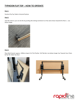
Please check if all the camera and accessories are included in the package.
All-In-One Camera
Manual CD
Hexagonal Wrench
Product Accessories
Quick Manual
NOTE: Mounting Accessories sold separately.

6
Part Name & Functions_Appearance
Introduction -
1
3
4
Dome Safety Wire
Prevents the dome cover from falling.
Dome Cover
Do not detach protection lm from dome cover before
finishing all installation process to protect dome cover
from scratches or dust. In the dome cover, there are fan
and heater to remove moisture on the bubble dome.
1
2
Sunshield & Upper Housing
Sunshield protect bubble dome cover from the sun rays and
rain fall. In the sunshield, there is the upper housing which
will contain accommodate PTZ mechanism. Also, the upper
housing will be connected to both mounting brackets and
dome cover.
PTZ Mechanism
Control the PTZ operations of the camera.
1
Sunshield & Upper Housing
2
PTZ Mechanism
3
Dome Safety Wire
4
Dome Cover

7
Part Name & Functions_Inside
Introduction -
1
6
7
8
9
ID Setup Switch
Specify the camera ID.
Communication Setup Switch
Set the transfer rate and protocols.
RS-485 Port
Used for RS-485 communications.
Power Port
Connect the power source here.
1
2
3
4
5
BNC Coaxial Cable
Connects to video output device such as monitor using the
BNC coaxial cable.
Alarm Output Port
It connects to the alarm lights, siren or lamps, and it is
activated according to the OSD menu or ‘Setup’ on the Web
-viewer setting.
Alarm Input Port
It connects to IR sensor, IrDA sensor or door switch. If the
sensor is activated, it can activate to move camera to the
specic angle and to connect the alarm device.
Fan
Defrosts the dome cover and removes moisture.
Heater
Defrost the dome cover in a low temperature by increasing
the internal temperature of the housing.
Alarm Output Port
Alarm Input Port
Fan
Heater
ID Setup Switch
Communication
Setup Switch
RS-485 Port
Power Port
2
3
4
5
6
7
1
Video Coaxial Cable
8
9

8
Installation -
Installation
2
2
1
3
Using the hole template, mark the holes on the wall or
ceiling.
After drilling the holes, x the four anchor bolts into the
holes.
Place the wall/ceiling mount bracket on the anchor bolts
properly and tighten the nuts on the anchor bolts.
Ceiling Mount Bracket Installation
(Bracket is Option)
Wall Mount Bracket Installation
(Bracket is Option)

9
Installation
Installation -
2
6
[2]
[1]
[3]
4
Detach the PTZ mechanism from the upper housing to plug
the main cable. When detaching the PTZ mechanism, press
down and hold up the black handles on both sides of the
PTZ mechanism.
Remove the protecting tape used to fix the PTZ
mechanism.
[1] Wind the waterproof tape around the pipe of housing.
[2] Hook the safety wire on the hole of pipe and the housing
safety cable hanger.
[3] Attach the upper housing to wall mount bracket by
turning it at least seven turns.
To secure the orientation of the housing, turn the ring
cap counter-clockwise until it is tight.

10
Installation
Installation -
2
Connect each of the following cables to the applicable port
and set the DIP switch to congure the camera ID,
communication protocol.
Video Output Cable
Alarm Input Port
Alarm Output Port
DIP Switch for Camera ID Setup
DIP Switch for Communication Setup
RS-485 Slot
Power Port
See the ‘DIP Switch Setup’ on 13, 14 page for details.
See the ‘Cabling’ on 15, 16 page for details.
a
b
c
d
e
f
g
Connect the dome safety wire to the upper housing.
8
7
a
b
g
c
d
e
f

11
Installation
Installation -
2
8
7
To lock the PTZ mechanism to the upper housing, press the
two black handles until a snap sound is heard.
Plug the connector of cable from junction box into properly.
After checking the orientation of one touch connector in the
upper housing, press the PTZ mechanism into hook in the
upper housing.

12
Installation
Installation -
2
10
9
Close the dome cover. Match the arrow mark on the dome
cover and the housing.
Tighten four screws on the dome cover in the sequence
shown in the image.
To maintain the best sealing, the torque of each screw
must be in the range of 0.5 ~ 1.0 N·m(0.3 ~ 0.73 lbf·ft).
Arrow Mark
Arrow Mark

13
DIP Switch Setup
Installation -
2
Before installing the camera, set up the DIP
switch to configure the Camera ID,
communication protocol, located on the
mount.
Interface Board
1. Communication Protocol Setup
Select the appropriate protocol with DIP switch combination.
- When the communication protocol setting is ‘Auto’, camera
will recognize SAMSUNG-E or PELCO-D / P protocol
automatically.
Any other DIP switch combinations will be recognized as Auto
protocol.
- If you want to control the camera using a DVR or a keyboard
controller, the protocol must be identical to the protocol set
on the camer.
- If you change the camera protocol by changing the DIP
switch, the change will be eective only after you reboot the
camera.
Protocol Setup Baud Rate Setup
RS-485
Termination Resistor
ON
8J
21 3 4 5 6 7 8
1
Auto - Factory Default
ON
8J
21 3 4 5 6 7 8
2
ON
8J
21 3 4 5 6 7 8
PELCO-D
3
ON
8J
21 3 4 5 6 7 8
PELCO-P
4
5
6
7
SAMSUNG
ON
21 3 4 5 6 7 8
Panasonic
8J
ON
21 3 4 5 6 7 8
GE(Kalatel)
8J
ON
21 3 4 5 6 7 8
AD(American Dynamics)
ON
8J
21 3 4 5 6 7 8

14
DIP Switch Setup
Installation -
2
2. Communication Baud Rate Setup
Select the appropriate baud rate with DIP switch combination.
4. Camera ID Setup
The ID number of the camera is set using binary numbers.
See the example below.
Interface Board
1
2
3
4
5
ON
8J
21 3 4 5 6 7 8
2400 BPS - Factory Default
ON
8J
21 3 4 5 6 7 8
4800 BPS
ON
8J
21 3 4 5 6 7 8
9600 BPS
ON
8J
21 3 4 5 6 7 8
19200 BPS
38400 BPS
ON
8J
21 3 4 5 6 7 8
3. RS-485 Termination Resistor
- Pin 8 is used for on/off of RS-485 termination.
- Normally, it must be OFF.
- When you have trouble with long daisy chain style
connections, turn ON this termination switch on the last
camera.
ON
8J
21 3 4 5 6 7 8
Pin 1 2 3 4 5 6 7 8
1 2 4 8 16 32 64 128ID Value
ex) ID=5
ex) ID=10
on
off
off
on
on
off
off
on
off
off
off
off
off
off
off
off
- If you want to control a certain camera, you must match the
camera ID with ‘CAM ID’ setting of DVR or keyboard controller.
- The range of Camera ID is 0~255.
- All cameras have a factory default Camera ID of 1.
- Camera ID will be effective without having to reboot the
camera.

15
2
Cabling
Installation -
1
3
2
RS-485 Communication (DVR/Keyboard)
To control multiple PTZ cameras at the same time, the
RS-485 communication lines should be connected in
parallel form as shown below.
Keyboard Controller/DVR
RS-485
#1 #2 #n
~
Video Output
Connects to video output device such as a monitor using a
BNC coaxial cable.
Power Connection
- Please check the correct rated power.
- The rated power is marked on the front of the inner box
and the side of the PTZ mechanism.
Rate Power Current Consumption
AC 24V
Video Output
1
Power
2
RS-485
RS-485
(Keyboard Controller/DVR)
3
AC 24V
F.G
Heater OFF: 24W, 1000mA | Heater ON: 57W, 2400mA

16
Cabling
Installation -
2
OUT1
OUT2
OUT3
OUT4
5
4
Alarm Output
There are 4 alarm outputs, and all of them are the relay
contact type. Polarity (AC/DC) and isolations between
channels do not need to be taken into consideration.
Make sure the power capacity of the relay contact matches
the instructions written above.
Out Out
N.C
Activation
Activation
N.O
In 2
COM
In 2
COM
In 2
COM
In 2
COM
The short circuit between the GND and Input pin
means alarm is activated.
Sensor Input/Sensor
To use the alarm input, the type of sensor must be selected
in OSD menu. Select from 'Normal Open' and 'Normal Close'.
If sensor type is not selected properly, the alarm can be
activated reversely.
COM
In 1
ALARM INPUT
GND1
2 3 4 5 6 7 8
Alarm Output
Alarm Input
Alarm Output
5
OUT1
OUT2
OUT3
OUT4
ALARM INPUT
GND1
2 3 4 5 6 7 8
Alarm Input/Sensor
COM
In 1
In 8
4

17
OSD Information
OSD -
10
11
12
8
9
23/MAR/2009
24 00 00
CAM
1
O 1---
I -2------
359/180/x100/SE
Alarm I/O Information
- This information shows current state of alarm input and
output.
- The ‘ I ’ means input and ‘O’ means output.
- If an input is on state it will show the number of input.
If an input is off state, ' - ' will be displayed. In the same way
‘O:1 - - -’ means output 1 is on and other output is off.
Ex) When point 2 of inputs are on, and output 1 is on, OSD
will show as below.
Compass Direction
- Shows the current compass direction of the camera.
- The direction is shown as N(North), S(South), E(East),
W(West), NE(Northeast), NW(Northwest), SE(Southeast),
SW(Southwest).
- See the section ‘ROOT MENU>SYSTEM SETUP>SET NORTH
DIRECTION’.
Zoom Magnification
Shows the current zoom magnification.
Tilt Angle in Degree
Shows the current tilt(0 ~ 180) angle.
Pan Angle in Degree
Shows the current pan(0 ~ 359) angle.
1
2
3
4
5
6
7
Preset Label
- The label stored for specific preset.
- See the section ‘ROOT MENU>FUNCTION SETUP>PRESET
SETUP>LABEL’.
Camera ID_Top
- If ‘CAMERA ID’ sets ‘TOP’, camera ID displayed in this area.
- See the section ‘ROOT MENU>DISPLAY SETUP>CAMERA ID’.
Camera ID_Bottom
- If ‘CAMERA ID’ sets ‘BOT’, camera ID displayed in this area.
- See the section ‘ROOT MENU>DISPLAY SETUP>CAMERA ID’.
Date / Time
- Shows the current date/time.
- See the section ‘ROOT MENU>SYSTEM SETUP>DATE/TIME
SETUP.’
Image Flip
- Shows that images are currently reversed by auto flip
function.
-
See the section ‘ROOM MENU>CAMERA SETUP>IMAGE FLIP’.
Address
- The current RS-485 address information.
- See the section ‘ROOT MENU>SYSTEM INFORMATION’.
Action Title
Followings are possible action titles and their meaning.
Action Title
SET PRESET 123
PRESET 123
PATTERN 1
SCN 1/PRESET 123
RANGE OVER
UNDEFINED
Means
Means to store preset 123.
Means it reached preset 123.
Means the camera is running pattern 1.
Means the camera is running scan 1.
Means the action received is not within the
range supported.
Means the action received is not defined.
3
PATTERN
1
PRESET LABEL
CAMERA ID_TOP
CAMERA ID_TOP
CAMERA ID_BOT
CAMERA ID_BOT
23/MAR/2009
24 00 00
CAM 1
O 1234
I 12345678
359/180/x100/SE
F
Date / Time
Action Title
Preset Label
Camera ID_Top
Camera ID_Bottom
Compass Direction
Zoom Magnification
Tilt Angle in Degree
Pan Angle in Degree
Alarm I/O Information
Image Flip
Address
7
10
11
12
8
9
5
6
2
1
3
4

18
General Rules of Menu Operation
OSD -
The menu items surrounded with < > always has its sub
menu.
To move from items to item in the menu, use joystick in the
up/down or left/right.
For all menu level, to go into sub menu, press near or enter
key.
To go to up-one-level menu, press far key.
To change a value of an item, use up/down of the joystick in
the controller.
Press near or enter key to save values and press far key to
cancel values.
3
2
1
6
5
3
4
Press
Near/Enter
or
Far Key
Joystick
Down
Joystick
Up
>
>
Press
Near/Enter
Key
Press
Far Key
>
>
Press
Near/Enter
Key
Press Far Key
>
>
Joystick
Down
Joystick
Up
>
>
ROOT MENU
- - - - - - - - - - - - - - - - - - - - - - - - - - -
<SYSTEM INFORMATION>
<DISPLAY SETUP>
<MOTION SETUP>
<FUNCTION SETUP>
<CAMERA SETUP>
<SYSTEM SETUP>
<SYSTEM INITIALIZE>
EXIT
ROOT MENU
- - - - - - - - - - - - - - - - - - - - - - - - - - -
<SYSTEM INFORMATION>
<DISPLAY SETUP>
<MOTION SETUP>
<FUNCTION SETUP>
<CAMERA SETUP>
<SYSTEM SETUP>
<SYSTEM INITIALIZE>
EXIT
6
>
34
5
DISPLAY SETUP
- - - - - - - - - - - - - - - - - - - - - - - - - - -
ADDRESS
CAMERA ID
PTZ INFORMATION
ACTION TITLE
PRESET LABEL
ALARM I/O
DATE/TIME
<
PRIVACY ZONE>
TEMPERATURE OFF
BACK
ON
OFF
AUTO
AUTO
AUTO
AUTO
ON
DISPLAY SETUP
- - - - - - - - - - - - - - - - - - - - - - - - - - -
ADDRESS
CAMERA ID
PTZ INFORMATION
ACTION TITLE
PRESET LABEL
ALARM I/O
DATE/TIME
<
PRIVACY ZONE>
TEMPERATURE OFF
BACK
ON
OFF
AUTO
AUTO
AUTO
AUTO
ON
DISPLAY SETUP
- - - - - - - - - - - - - - - - - - - - - - - - - - -
ADDRESS
CAMERA ID
PTZ INFORMATION
ACTION TITLE
PRESET LABEL
ALARM I/O
DATE/TIME
<
PRIVACY ZONE>
TEMPERATURE OFF
BACK
OFF
OFF
AUTO
AUTO
AUTO
AUTO
ON
2
1

19
ROOT MENU & SYSTEM INFORMATION
OSD -
3
ROOT MENU
- - - - - - - - - - - - - - - - - - - - - - - - - - -
<SYSTEM INFORMATION>
<DISPLAY SETUP>
<MOTION SETUP>
<FUNCTION SETUP>
<CAMERA SETUP>
<SYSTEM SETUP>
<SYSTEM INITIALIZE>
EXIT
ROOT MENU
SYSTEM INFORMATION
FIRMWARE VER
Shows the current firmware version and date of upgrade.
COLOR SYSTEM
Shows the current analog video system.
PROTOCOL
Shows the current PTZ control protocol.
BAUD RATE
Shows the current baud rate of the PTZ control.
ADDRESS
Shows the current camera ID of the PTZ control.
11
11
SYSTEM INFORMATION
- - - - - - - - - - - - - - - - - - - - - - - - - - -
FIRMWARE VER
COLOR SYSTEM
PROTOCOL
BAUD RATE
ADDRESS
BACK
EXIT
2
.00-39
2011
-01-01 [21]
NTSC
AUTO
2400
1
ROOT MENU
- - - - - - - - - - - - - - - - - - - - - - - - - - -
<SYSTEM INFORMATION>
<DISPLAY SETUP>
<MOTION SETUP>
<FUNCTION SETUP>
<CAMERA SETUP>
<SYSTEM SETUP>
<SYSTEM INITIALIZE>
EXIT
<SYSTEM INFORMATION>
Shows information and current configuration.
<DISPLAY SETUP>
Enable/Disable of OSD display on main screen.
<MOTION SETUP>
Setup for motion related settings.
<FUNCTION SETUP>
Setup for various functions such as preset, scan, pattern, group and
schedule.
<CAMERA SETUP>
Configure camera related functions and data.
<SYSTEM SETUP>
Configure for basic system setup.
<SYSTEM INITIALIZE>
Initializes system configuration and sets all data to factory default
configuration.

20
DISPLAY SETUP > CAMERA ID
OSD -
3
> >>
Press Near/Enter Key
Press Near/Enter Key
Press Near/Enter Key
1
3
4
5
2
2
5
3
4
Joystick Right
DISPLAY SETUP
- - - - - - - - - - - - - - - - - - - - - - - - - - -
ADDRESS
CAMERA ID
PTZ INFORMATION
ACTION TITLE
PRESET LABEL
ALARM I/O
DATE/TIME
<
PRIVACY ZONE>
TEMPERATURE OFF
BACK
ON
BOT
ON
ON
ON
ON
ON
DISPLAY SETUP
- - - - - - - - - - - - - - - - - - - - - - - - - - -
ADDRESS
CAMERA ID
PTZ INFORMATION
ACTION TITLE
PRESET LABEL
ALARM I/O
DATE/TIME
<
PRIVACY ZONE>
TEMPERATURE OFF
BACK
ON
BOT
ON
ON
ON
ON
ON
DISPLAY SETUP
- - - - - - - - - - - - - - - - - - - - - - - - - - -
ADDRESS
CAMERA ID
PTZ INFORMATION
ACTION TITLE
PRESET LABEL
ALARM I/O
DATE/TIME
<
PRIVACY ZONE>
TEMPERATURE OFF
BACK
ON
BOT
ON
ON
ON
ON
ON
CAMERA ID
- - - - - - - - - - - - - - - - - - - - - - - - - - -
- - - - - - - - - - - - - - - - - - - - - - - - - - -
OK
CANCEL
1 2 3 4 5 6 7 8 9 0
A B C D E F G H I J
K L M N O P Q R S T
U VWX Y Z a b c d
e f g h i j k l mn
o p q r s t u v w x
y z
< >
-
/
: .
CAMERA ID
- - - - - - - - - - - - - - - - - - - - - - - - - - -
- - - - - - - - - - - - - - - - - - - - - - - - - - -
OK
CANCEL
1 2 3 4 5 6 7 8 9 0
A B C D E F G H I J
K L M N O P Q R S T
U V W X Y Z a b c d
e f g h i j k l mn
o p q r s t u v w x
y z
< >
-
/
: .
AAAAAAAAAAAAAAAAAAAAAAAA
BBBBBBBBBBBBBBBBBBBBBBBB
1
ADDRESS
CAMERA ID
Select the camera ID location. Refer to ‘OSD Display of Main Screen’.
PTZ INFORMATION
ACTION TITLE
PRESET LABEL
ALARM I/O
DATE/TIME
<PRIVACY ZONE>
Start Privacy Zone Mask setup Menu.
TEMPERATURE
ON / OFF
BOT / TOP / OFF
ON / OFF / AUTO
ON / OFF / AUTO
ON / OFF / AUTO
ON / OFF / AUTO
ON / OFF
CELSIUS / FAHRENHEIT / OFF
2
1
DISPLAY SETUP
This menu defines enable/disable of OSD display on main screen.
If an item is set to be ‘AUTO’, the item is displayed only when the
value of it is changed.
3
4
CAMERA ID - Alphabet Input
- Edits the camera ID to show on monitor when camera ID sets
‘TOP(Top)’ or ‘BOT(Bottom)’.
- Max. 48 alphabets are allowed(Including space).
CAMERA ID - Complete Editing
If you complete the camera ID editing, move the cursor to ‘OK’
and press near key to save the completed camera ID. To abort
the current change, move the cursor to ‘CANCEL’ and press the
near key.
LABEL PRESET1
- - - - - - - - - - - - - - - - - - - - - - - - - - -
[ ]
OK
CANCEL
- - - - - - - - - -
1 2 3 4 5 6 7 8 9 0
A B C D E F G H I J
K L M N O P Q R S T
U VWX Y Z a b c d
e f g h i j k l mn
o p q r s t u v w x
y z
< >
-
/
: .
Current Cursor Position: In edit label menu, a reverse rectangular
is cursor. As soon as finishing selecting alphabet, cursor moves to
the next digit.
Selecting Alphabet: Using left/right/up/down of joystick, move
to an appropriate character from the character set. To choose the
character, press the near or enter key.
Space: If you want to use blank, choose space character (’ ‘).
Back-Space:
If you want to delete a character in front, use back
space character (’ ‘).
Cursor button: Use this button to move the
Current Cursor( )
for left or right direction.
d
e
a
a
b
c
d
a
b
c
/