
KESMAC
Transportable Reel Mowers
3, 5, 7, 9 and 11 Gang Mowers
Fairway Mowers
Vertical Mowers
Operators Manual
Manual Part No. KM99026. Rev. 05/07
KESMAC Inc.
23324 Woodbine Avenue, Keswick Ontario Canada L4P 3E9
Tel (905) 476-6222 Fax (905)-6744 Web Site www.Kesmac.com

KESMAC Transportable Reel Mowers
FOREWORD
The Operator’s Manual must be kept on the machine at all times.
The Manual is provided to give the Owner/Operator the correct information on the safe operating procedures, minor
repairs and the maintenance of the machine. Important features and specifications are included to help you operate
your Kesmac mower safely and efficiently.
All Kesmac machines are tested and inspected before leaving the factory to ensure that all safety devices and
safety decals are in place. Do not operate the machine if any safety device or decal is damaged or missing.
IMPORTANT
Follow the recommended operating practices, and the service/maintenance procedures, as outlined in the manual
to ensure continued safe and satisfactory performance of the mower.
Questions relating to service or repair, that may be beyond the scope of this manual, should be directed to your
Kesmac Dealer or to the factory Service Department.
Kesmac has a policy of continued product improvement and development, and reserves the right to change design
and specifications without notice, or obligation to modify previously manufactured machines.
IMPORTANT
Record the Serial Number of the machine. It must be quoted when
ordering parts or placing a service call to the factory.
Manual Part No. KM99026. Rev. 05/07

CONTENTS
SAFETY PRECAUTIONS 1
GENERAL SAFETY 2
Before Operating 2
During Maintenance 3
Safety Symbols 3
Safety Decals 4
Operating Conditions 7
DAILY INSPECTION 8
Tires and Wheels 8
Drive Belts & Sheaves 10
PTO Shafts 11
Tongue and Hitch 11
Hydraulic System 12
Guards and Decals 12
Initial Operation Check 12
HOOK-UP TO TRACTOR 13
Transport 14 BACKLAPPING UNIT 44
HYDRAULIC LIFT OPERATION 16
LIFT CAIN ADJUSTMENT 20
MOWING PROCEDURE 22
Cutting Height Adjustment 23
Reel to Bedknife Adjustment 24
Single point Adjustment 25
VERTICAL MOWER
Depth of Cut Adjustment 26
Drive Belts Adjustment 26
Operation 27
MAINTENANCE 28
Lubrication Chart 30
Gearbox Lubrication 31
Wheel Change – Main Wheel 33
Wheel Change – Out Rigger 35
Wing Kick Springs 36
Main Drive Belts 37
Reel Drive Belts 38
Jackshaft Bearing Replacement 41
PTO Shafts Set-Up 41
SPECIFICATIONS 42
Backlapping 44
Reel & Bedknife Grinding 46
ELEVEN GANG
Optional Castor Wheel 47
LIFT CHAINS 48
Attaching Dimensions 48
TORQUE CHART 49

SAFETY PRECAUTIONS
The correct operating procedures, and strict adherence to recommended service schedules, are important
in contributing to the safe operation of the machine and the safety of the operator and others.
It is important when carrying out service or repair work on Kesmac Mowers to follow all of the operating and service
safety procedures that are outlined in this manual, to ensure your own safety and that of any bystanders.
It is not possible to identify all possible situations that may arise that could possibly affect the safety of service
personnel or bystanders and the machine, therefore Kesmac cannot list all possible precautions that may prevent
accidents.
The Owner/Operator, and service personnel, must assume responsibility for their own safety, the safety of others
and of the machine, by following all safety instructions, and fully understanding the safe operation of the machine as
outlined in the operator’s manual.
The operator should at all times be aware of any potential safety hazards, and take corrective action immediately if
a dangerous situation should arise.
If you do not understand……….ASK
Kesmac Inc. will not be responsible for any damages, or claims from damages, arising from the unauthorized
modification of its products, or the use of replacement parts that are not genuine Kesmac replacement parts, or
parts that do not meet Kesmac Engineering manufacturing specifications.
It is recommended that Kesmac products should be serviced, maintained and repaired only by qualified service
personnel.
1

SAFETY PRECAUTIONS – General Safety
The Operator’s Manual brings to your attention
situations that can arise during the safe and routine
operation of your Kesmac Mower.
It also informs you how to deal with non-routine
conditions and situations, and avoid possible injury to
yourself or to others.
The manual outlines the safe practices that must be
followed when operating the mower when it is
equipped with standard equipment.
Note that attachments which are not specified by
Kesmac may affect the safe performance of the
machine, and are used at the Owner/Operator’s risk,
as they are not supplied or approved by Kesmac Inc.
BE A QUALIFIED OPERATOR BY :
• Reading and understanding the written
instructions in the Operator’s Manual and
also on the safety decals on the Mower and
the Tractor.
• Receiving training on the operation of the
Mower and the Tractor.
• Asking your equipment dealer or supervisor
to explain things you do not understand.
• Explain the written instructions in the
operator’s manual and on the safety decals to
operators who cannot read.
BEFORE OPERATING THE MOWER
Read this manual and any others supplied with the
machine.
Check that all safety decals and safety guards are
correctly located and are not damaged
MAINTENANCE SAFETY
Before doing any maintenance or service work :
• Due to moving heads, spring loadings, sharp
blades, and other potential injury causing
factors, exercise caution in the placement of
fingers and hands when carrying out
adjustments or repairs.
• Adjustments or service work must only be
done when the Reels are stationary and have
been lowered to the ground, the PTO is
disengaged and the tractor engine is
switched off. (If the tractor is attached to the
mower).
2

SAFETY PRECAUTIONS
During Maintenance
• Use only genuine Kesmac parts. Parts that are not supplied by Kesmac may not meet Kesmac Engineering
specifications or standards of manufacture.
• The use of parts not approved by Kesmac may result in component failure possibly resulting in an accident and
injury to the operator or bystanders.
• Relieve pressure in hydraulic systems before attempting to carry out any service work. Failure to observe this
precaution may result in serious personal injury.
SAFETY ALERT SYMBOL The warning /safety Decals are prominently displayed
and strategically located on the machine.
Hazards are identified by this symbol, followed by the
Signal words DANGER, WARNING or CAUTION Check regularly that Decals are not missing, and are
easily readable. Do not operate the machine if any of the
decals are damaged or missing.
DANGER
Indicates an immediate situation which if not corrected It is important that the operator is familiar with the Safety
or avoided WILL result in death or serious injury. Decals.
WARNING Do not operate the machine if drugs, alcohol or any
Indicates a potential hazardous situation which COULD medications are being used which can affect alertness
result in death or serious injury. or co-ordination.
Seek professional advice before operating the machine
CAUTION if in doubt about the side affects from any medication being
Indicates a potentially hazardous situation which MAY taken that may put your safety at risk.
result in a minor or moderate injury.
3

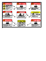
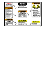
DECALS. See Pages 5 & 6 also.
4


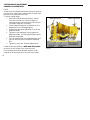
GENERAL SAFETY
Operating Conditions
Commercial mowers are subjected to a variety of
ground conditions. Mowing machine operators must
understand the need to pay constant attention to the
changing conditions that they may encounter while
operating the machine.
These precautionary measures will help in more
efficient operation and reduced equipment ‘down time’.
IMPORTANT
Positive drive PTO Mowers have a powerful cutting
action, very little will ‘stop’ them.
This type of mower will ‘swallow’ sand, mud, sticks,
cans, golf balls and other debris that would ‘stop’ other
types of mowers.
Contact with such debris will drastically reduce the
Blade and Bedknife sharpness and result in a loss of
the quality of cut.
Contact with debris can also cause damage to, or the
brakedown, of the mower.
Look after your Mower……and it will look after
your mowing.
7
WARNING
• Guards are installed by the manufacturer
for your protection and that of bystanders.
• Do not engage the PTO with the mower
reels in their raised, (transport), position.
• Do not raise the mower reels when the PTO
is engaged.
• The PTO must be disengaged and the reels
stationary before the mower reel units are
raised.
• Keep clear of all moving parts.

DAILY INSPECTION
To enable customers to implement service procedures,
and design changes that are recommended to improve
the operation and service life of the mower, Service
Bulletins are issued by the factory.
It is important that Service Bulletin instructions are
implemented as soon as possible.
IMPORTANT
At the end of the workday clean the mower thoroughly.
If a pressure washer is used do not direct the high
pressure water jet directly at the Bearing Seals, to do
so will force water into the bearings and result in
bearing failure.
MAINWHEEL BEARINGS
Mower Units up to Serial No. 356 have Sealed Bearings
that do not require lubricating during service.
Refer to pages 35 and 36 for service procedure on the
revised axle designs, with Cup and Cone Bearings, that
are fitted from Serial No. 357 onwards.
TIRES
Main and Outrigger.
All tires should be visually inspected each day for
excessive wear, bulges or any other damage.
• Refer to the Tire Sidewall for the recommended
operating pressure.
• Check the Wheel Lug Nuts for tightness.
The Wheel Nuts should be tightened to 90 ft.lb.
torque.
Pay particular attention to the above if the machine is
frequently transported on highways or on rough roads.
NOTE
Turf tires are not designed for use on highways.
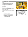
OUTRIGGER WHEELS
Mower Units Serial No. 1 to 73 (and also No.87) have
Dual Outrigger Wheels.
All machines after No.73 have Single Outrigger Wheels.
Dual Outrigger Wheels have a single Roller Bearing
pressed into the Wheel Hub, and retained by a Collar at
each end of the axle.
Cont…
8

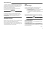
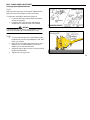
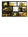
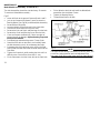
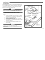
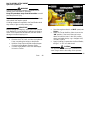
DAILY INSPECTION Cont..
OUTRIGGER WHEELS
Fig.1
Serial No. Up to 73. Dual Wheels.
It is important that the Roller Bearings and Hub Cavity
are kept packed with grease. Apply grease daily.
IMPORTANT
Also check that the Lock Collars at both ends of the Axle
are locked to the Axle by the Set Screws
Fig.2
Serial No. 74 onwards. Single Wheel.
Mowers with the Taper Roller Bearings, (Cup and Cone),
do not require daily maintenance.
Refer to pages 33, 34 and 35 for service procedure.
9
Fig.1
Fig.2

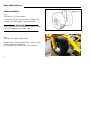
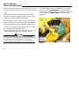
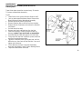
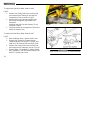
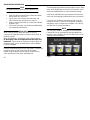
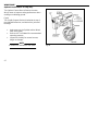
DAILY INSPECTION
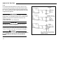
DRIVE BELTS AND SHEAVES
Fig.3
Check all Drive Belts for signs of cracking, excessive
wear, cuts, or stretching.
Sheaves must be kept free of debris.
Worn Sheaves allow a belt, that has no excessive
wear, to ‘bottom out’ in the ‘vee’ groove.
A shiny, polished track in the bottom of the ‘vee’
groove is evidence of a badly worn drive belt and/or
Sheave.
PRIMARY BELTS
Fig.4
The Primary Drive Belts are tensioned by spring
tensioned ‘idlers’.
There should be 1/2 inch deflection of the belt when
pressed ‘down’ mid-way between the Sheaves.
Increase or decrease the belt tension by adjusting the
Belt Idler Adjusting Nut.
REEL DRIVE BELTS
Fig.5
Check that the Telescopic Arm is free by pulling it ‘up’,
it should slide freely against spring pressure.
Apply grease to the grease fitting.
Fig.3
Fig.4
Fig.5
10

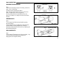
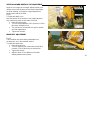
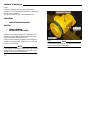
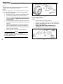
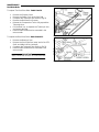
DAILY INSPECTION
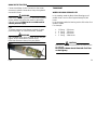
PTO SHAFT
Fig.6
The PTO Shaft must be installed, relative to the tractor,
as shown.
WARNING
Do not operate the machine without the PTO Shaft
Shields in place. To do so could result in serious
personal injury.
The PTO Manufacturers Service Manual is supplied
with the machine.
It is important that inspection, service and maintenance
instructions for the PTO are followed.
Grease the PTO daily.
TONGUE TUBE
Fig.7
Check the nuts and bolts ‘A’ for tightness.
Lubricate the Swivel Hitch at grease fitting ‘B’
11
Fig.6
Fig.7

DAILY INSPECTION
HYDRAULIC SYSTEM
• Check all hydraulic fittings, connections and
hoses for signs of leaks, damage or wear.
• Hoses must be routed clear of any moving
parts, and secured to prevent ‘rubbing’ to
prevent damage.
• Keep all hydraulic connections clean.
Refer to pages 16 to 19 for the hydraulic system
diagrams and operation.
GUARDS AND DECALS
Before starting mowing operations :
• Check that all safety Guards are in place and
not damaged.
• Check that all Safety/Warning Decals are in
place, are clean and readable.
WARNING
Do not operate the machine if any Safety Guards or
Safety/Warning Decals are missing or damaged.
To do so may result in serious personal injury.
INITIAL OPERATION CHECK
After the first 10 hours of operation :
• Check all fasteners for tightness.
• Check the Main Wheel Retainer Bolts.
Remove the lower bearing Blocks. Check that
the Bearing Retainer Washers are tightly
locked by the Retainer Bolts. (Refer to illustra-
tions on pages 34 and 35). If the washer is
loose, remove the Retainer Bolt and apply
‘Loctite 242’ to the threads and refit the bolt and
washer. Torque the Retainer Bolt to 76 in/lb.
Re-assemble the Lower bearing Blocks.
IMPORTANT
With the Lower Bearing Blocks removed check also that
the inner races of the bearings show no signs of turning
on the axle shaft.
This check should be done at regular service
intervals.
For main axles with Taper Roller Bearings refer to
pages 33 and 34.
12

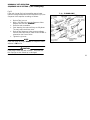
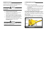
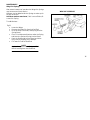
HOOK-UP TO TRACTOR
Fig.8
It is important that the Mower Frame is ‘level’ for the
correct set-up for mowing. Connect the Mower Swivel
Hitch to the Tractor Draw Bar using an approved Draw
Pin. The front and rear Jack Shafts should be the same
height from the ground.
IMPORTANT
Adjust the Swivel Hitch to set the Mower Frame level to
the ground. It is removable to allow it to be rotated 180
degrees to increase the adjustment relative to the
Tractor Draw Bar.
(Optional Ball Hitch also illustrated).
IMPORTANT
The use of a Draw Bar hung between the 3-Point
Hitch Arms is not recommended.
Connect the PTO Shaft to the Mower Gearbox and the
Tractor Tail Shaft, see Fig.6, and secure the Shields.
WARNING
The PTO Shields are identified : Tractor End and Mower
End. If Shields are missing do not operate the
Mower.
13
Fig.8

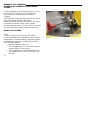
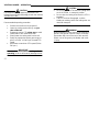
HOOK-UP TO TRACTOR
Connect the Mower ‘Quick Connects’ to the tractor
accessory hydraulic connections. Keep the hydraulic
connections clean.
WARNING
Relieve any hydraulic pressure in the mower hydraulic
system before connecting the mower to the tractor
hydraulic system. Failure to do so could result in
serious personal injury
.
Fig.9
To relieve pressure in the Mower Hydraulic System
press the plunger ‘A’ in the Disconnect, ‘inwards.’
WARNING
Use a suitable tool or piece of wood, do not use your
fingers as this could result in serious injury.
Direct the disconnect away from your person.
Fig.9
TRANSPORT
WHEEL BEARING SERVICE LIFE
In the mowing mode the Main Wheel Bearings on all
models have a service life of approximately 20,000
hours.
In the transport mode the bearing service life varies from
model to model.
For example :
• 11 Gang 500 Hours.
• 9 Gang 750 Hours
• 7 Gang 850 Hours.
• 5 Gang 1400 Hours.
CAUTION
Maintain the correct tire pressures, as shown on the
tire sidewall.
Do not tow a Mower that is fitted with Turf Tires
on the highway.
14

TRANSPORT
LOWERING THE REELS
Before ‘lowering ‘ the Reels, position the Mower on
level ground. If on a slope face the mower ‘up hill’,
this allows the reels to lower evenly on both sides, and
prevents damage to the Reel Drives.
Check that the transport Safety Chains are un-hooked
from the Reels and are in their ‘stowed’ position.
IMPORTANT
To prevent damage to the Reels do not lower them with
the Safety Chains in their transport positions.
Do not set the tractor engine RPM too high.
Shift the Tractor Hydraulic Control Valve Lever to the
‘DOWN’ position.
Return the Control Valve Lever to ‘NEUTRAL’ when all
Reels are fully down.
CAUTION
Check all chains regularly for damage, and that all
Shackles are securely wired.
Failure to observe this precaution could result in an
accident and personal injury
15
LIFTING THE REELS
Shift the Tractor Hydraulic Control Valve Lever to the
‘UP’ position.
Return the Control Valve Lever to ‘NEUTRAL’ when
the Reels are fully raised.
Re-attach the Safety Chains.
TRANSPORT SAFETY CHAINS
When transporting or storing the Mower, the Transport
Safety Chains must be attached from the Main Lift
Arms to the opposite side Wing Reels.
CAUTION
Do not engage the PTO with the Reels in the raised
(transport) position.
The PTO must be disengaged and the Reels
stationary before the Reels are raised.

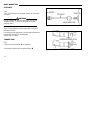
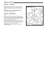
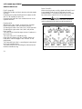
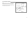
HYDRAULIC LIFT OPERATION
REEL/WING - LIFT SEQUENCE
Fig.10.
From Serial No. 232. (See Fig.11 for earlier machines)
Hydraulic oil pressure to the ‘raise’ circuit lifts the five main
reels first, followed by the wing reels and lastly the wing
frames.
The cylinders are ‘locked up’ by Pilot Check Valves.
The Pilot Check Valves are released by pressure on the
‘lower’ side of the hydraulic circuit.
REEL/WING - LOWER SEQUENCE
Fig.10
Hydraulic oil flow in the ‘LOWER’ circuit is stopped by the
Sequence Valve until the wing cylinders are fully extended.
Oil pressure is then sufficient to open the Sequence Valve
and ensure that the wing frames will ‘LOWER’ first, then the
wing reels, followed by the main reels.
Pilot Check Valves in the Valve Block remain ‘closed’, until
pressure via the return lines ‘opens’ them allowing return oil
to escape from the cylinder. This prevents the reels from
‘creeping down’ from the transport position.
Restrictors in the wing cylinders prevent the wings from
‘lowering’ too quickly.
Fig.10
16

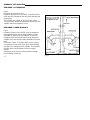
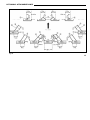
HYDRAULIC LIFT OPERATION
REEL/WING - LIFT SEQUENCE
Fig.11
Machines up to Serial No. 231.
Hydraulic oil pressure to the ‘RAISE’ circuit lifts the five
main reels first, followed by the wing reels and lastly the
wing frames.
The cylinders are ‘locked up’ by Pilot Check Valves.
The Pilot Check Valves are released by pressure on the
‘LOWER side of the hydraulic circuit.
REEL/WING - LOWER SEQUENCE
Fig.11
Hydraulic oil flow in the ‘LOWER’ circuit is stopped by
the Sequence Valve until the wing cylinders are fully
extended. Oil pressure is then sufficient to open the
Sequence Valve and ensure that the wing frames will
‘LOWER’ first, then the wing reels, followed by the main
reels.
Pilot Check Valves in the Valve Block remain ‘closed’
until pressure via the return lines opens them allowing
the return oil to escape from the cylinder. This prevents
the reels from ‘creeping down’ from the transport
position.
A Restrictor in the Check Valves prevents the wings
from ‘lowering’ too quickly.
17
Fig.11
Page is loading ...
Page is loading ...
Page is loading ...
Page is loading ...
Page is loading ...
Page is loading ...
Page is loading ...
Page is loading ...
Page is loading ...
Page is loading ...
Page is loading ...
Page is loading ...
Page is loading ...
Page is loading ...
Page is loading ...
Page is loading ...
Page is loading ...
Page is loading ...
Page is loading ...
Page is loading ...
Page is loading ...
Page is loading ...
Page is loading ...
Page is loading ...
Page is loading ...
Page is loading ...
Page is loading ...
Page is loading ...
Page is loading ...
Page is loading ...
Page is loading ...
Page is loading ...
-
 1
1
-
 2
2
-
 3
3
-
 4
4
-
 5
5
-
 6
6
-
 7
7
-
 8
8
-
 9
9
-
 10
10
-
 11
11
-
 12
12
-
 13
13
-
 14
14
-
 15
15
-
 16
16
-
 17
17
-
 18
18
-
 19
19
-
 20
20
-
 21
21
-
 22
22
-
 23
23
-
 24
24
-
 25
25
-
 26
26
-
 27
27
-
 28
28
-
 29
29
-
 30
30
-
 31
31
-
 32
32
-
 33
33
-
 34
34
-
 35
35
-
 36
36
-
 37
37
-
 38
38
-
 39
39
-
 40
40
-
 41
41
-
 42
42
-
 43
43
-
 44
44
-
 45
45
-
 46
46
-
 47
47
-
 48
48
-
 49
49
-
 50
50
-
 51
51
-
 52
52


Kenmore 3 User manual
- Type
- User manual
- This manual is also suitable for
Ask a question and I''ll find the answer in the document
Finding information in a document is now easier with AI
Other documents
-
Toro Belt Cover Bracket, 300 Series Garden Tractors Installation guide
-
Ransomes HF-5 User manual
-
-
Gleason Reel ACA/ACC Cord Reels Installation guide
-
Locke TRM-3083 User manual
-
-
-
-
-
 National Mower 8400 0308 User manual
