Rinnai Australia 3 Slimfire 252 Operation & Installation Manual
SAFETY
• Failure to comply with these instructions could result in a fire or explosion, which could cause
serious injury, death or property damage.
• Improper installation, adjustments, service or maintenance can cause serious injury, death or
property damage. Such work must be performed by an authorised person.
• The appliance must be installed in accordance with the local gas and electrical authority
regulations.
• Flue terminal must always vent directly to outdoors.
• DO NOT extend the flue vertically or horizontally in ways other than prescribed in the appliance
manufacturers’ installation instructions.
• For information on gas consumption, see data plate on the appliance.
• This appliance must not be installed where curtains or other combustible materials could come
into contact with it. In some cases curtains may need restraining.
• WARNING: This heater MUST NOT
be used if either of the glass
panels are damaged.
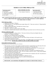
• When considering installation
ensure minimum clearances as
follows are adhered to, refer Fig. 1.
• Heat radiating from the front of this
heater may over time affect the
appearance of some materials
used for flooring such as carpet,
vinyl, cork or timber. This effect
may be amplified if the air in the
room contains cooking vapours or
cigarette smoke. To avoid this
possibility, it is recommended that
a mat or similar protective sheet be
placed in front of the appliance,
extending at least 750 mm in front
of the glass guard.
• This appliance is not intended for use by persons (including children) with reduced physical,
sensory or mental capabilities or lack of experience and knowledge, unless they have been given
supervision or instruction concerning use of the appliance by a person responsible for their
safety.
• The appliance is not intended for use by young children or infirm persons without supervision.
• Young Children must be supervised when in the vicinity of this heater while it is in operation.
• The Glass Dress Guard MUST be fitted to this appliance to reduce the risk injury from serious
burns and no part of it should be permanently removed.
• For protection of young children or the infirm a secondary guard is required.
• If the supply cord is damaged or requires replacing, it must be replaced by the manufacturer or
the manufacturer's agent or similarly qualified person in order to avoid a hazard.
• The heater must not be located immediately below a power socket outlet.
• DO NOT connect to an LPG Gas cylinder indoors.
• A dedicated 240 V earthed 10 Amp power point must be used with this appliance.
• DO NOT modify this appliance. Modifying from original specifications may create a dangerous
situation and will void your warranty.
• Only the flue components specified by Rinnai must be used.
• Unpack the heater and check for damage. DO NOT INSTALL A DAMAGED HEATER. If the heater
is damaged, contact your supplier for advice.
• Before installing the heater, check the label for the correct gas type (refer data plate, inside the
appliance).
• Refer to local gas authority for confirmation of the gas type if you are in doubt.
• This heater must be installed by an authorised person.
Note that side and vertical
clearances are measured
from the edge of the glass.
300mm
300mm
300mm
750mm
1000mm
Fig .1