1
MODELS GLM #3000, #9000 & #3701
FOR OUTDOOR USE ONLY
7” Water Column for Natural Gas
`
THE LAMP HEAD MUST BE INSTALLED TO CONFORM WITH LOCAL CODES OR IN ABSENCE OF
LOCAL CODES WITH THE NATIONAL FUEL GAS CODE ANSI Z2231.1 LATEST EDITION.
CAN 1-B149.1 OR CAN 1-B149.2
POST INSTALLATION:
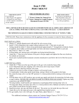
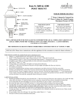
1. Obtain from your dealer 3” OD post.
2. Install inside post (1/4” od) refrigeration type copper tubing with ¼” flare nuts at each end. Tubing should be
coiled 1 ½ times at top.
3. Tubing should protrude about 6” through hole at bottom of post.
4. Dig a hole 21” deep X 12” wide.
5. Attach the ¼” flare nut at bottom of post to gas supply.
6. Secure post in plumb position and pour concrete around post to just below the level of the line access hole.
INSTALLATION OF LAMP
1. Connect gas supply line to tubing with the ¼” flare nuts at the base of the post and tighten flare nuts
clockwise. No sealants are necessary
2. Install screen, rain shield and finial to top of lamp.
3. Attach gas valve to ¼” flare nut on the copper tubing.
4. Lower lamp onto post and tighten setscrews in the collar of lamp so the lamp is well secured to post.
5. Install mantles (instructions on pack).
6. Check all gas connections for leaks using soap solution. If air bubbles appear, shut off main gas line and
tighten all fittings. NEVER USE AN OPEN FLAME TO CHECK FOR GAS LEAKS!
WALLMOUNT INSTALLATION
The manufacturer does not attach the gas lamp to the wall bracket.
1. When choosing a location for the gaslight it should be located low enough that the top of the lamp will not be
closer than two feet to any combustible material above the lamp or 18” from either side.
2. The supply tube should be connected to a gas source provided at the desired location. All connection and
installation materials must be approved by local, city, state and national codes.
3. After the lamp has been connected to the gas supply and before it is attached to the supporting wall, the
connection should be tested for leaks. Note: never use a match to check for a leak! A soapy solution applied
with a brush works best for finding a leak.
4. Once the connection is made and there are no leaks, the bracket may be attached to the wall. Be careful not to
kink the supply line when attaching the bracket.
5. Secure the aluminum stud inside the wall bracket by tightening setscrew.
6. Secure lamp to bracket by tightening setscrews in collar to the aluminum stud.
7. Install Mantles (Instructions on back).
FOR YOUR SAFETY
If you smell gas:
1. Shut off gas to the appliance.
2. Extinguish any open flame.
3. If odor continues, immediately
call gas supplier.
FOR YOUR SAFETY
Do not store or use gasoline
or other flammable vapors
and liquids in the vicinity of
this or any other gas appliance.
INSTALLER: Leave instructions with appliance for consumer to retain for future reference

2
MAINTENANCE INSTRUCTIONS:
No combustible material, gasoline or other flammable vapors or liquids should be stored near lamp. Nothing should obstruct the flow of
combustion and ventilation air. Occasionally the glass will need to be cleaned with household glass cleaner and mantles should be visually
checked, for condition and burn, replace mantles if necessary (refer to the lighting instructions) Gas lamp parts and mantles (inverted, soft
auto form or hard inverted mantles) are available from your local gas appliance dealer or:
AMERICAN GAS LAMP WORKS
101 HOEVELER ST
SPRINGDALE PA 15144
(Toll Free) 855-427-5483
CAUTION
TURN GAS SUPPLY OFF AND WAIT FOR LAMP TO COOL BEFORE STARTING ANY REPAIRS.
REMOVE AND CLEAN GLASS AND REPLACE BROKEN MANTLES AS NECESSARY.
LIGHTING INSTRUCTIONS
STEP #1
Remove one glass panel by pushing glass up from bottom corners with forefingers, then pulling forward slightly and
lowering.
STEP #2
Install mantle over ceramic nozzle, gently pull down mantle for proper shaping (soft mantles). For hard mantles do
not touch fabric, just place mantle on the nozzle. With gas turned off, hold a lighted match up to but not touching
mantle to burn off protective coating.
STEP #3
Using a screwdriver, turn gas on at the valve. Light mantle with match being careful not to touch the mantle.
STEP #4
Replace glass by fitting top edge into frame top. Pressing glass against tabs inside of the frame and allowing glass to
slide into bottom frame. (if glass does not slide down on its own press in and down on the glass.)
STEP #5
Using a screwdriver, adjust flame with on/off valve to its brightest, but containing flame within mantle.
/


