Cannon Fitzroy Specification

Category
Water heaters & boilers
Type
Specification

This manual is also suitable for

Cannon Fitzroy is an inbuilt gas heater that combines style with functionality. Designed for use with natural or propane gases, it boasts a 26 MJ/hr gas consumption and 5.98 kW energy output. Its electronic direct spark controller and 3-speed fan ensure efficient and convenient heating. With a 10-year warranty on the heat exchanger, you can trust in its long-lasting performance.

Cannon Fitzroy is an inbuilt gas heater that combines style with functionality. Designed for use with natural or propane gases, it boasts a 26 MJ/hr gas consumption and 5.98 kW energy output. Its electronic direct spark controller and 3-speed fan ensure efficient and convenient heating. With a 10-year warranty on the heat exchanger, you can trust in its long-lasting performance.

Cannon
FITZROY INBUILT
USER INSTRUCTIONS
INSTALLATION INSTRUCTIONS
SERVICE INSTRUCTIONS
Gmk10025
AS4553:2008
This heater is approved for use with
Please leave instructions with the owner
Part No: F2903
Revision K - 2010
Cannon
For service to this appliance or spare
parts contact the CANNON distributor:
email: service@sampfordixl.com.au
28
Sampford IXL (spare parts)
Phone: 1300 727 421
Fax: 1300 727 425
Data label
FITZROY INBUILT
Natural and Propane gases.
Attach copy of data label here!
PLEASE READ THIS MANUAL
BEFORE INSTALLING AND
USING THIS HEATER.
DON’T RISK YOUR APPLIANCE WARRANTY
ONLY A LICENSED PERSON WILL GIVE YOU A COMPIANCE
CERTIFICATE, SHOWING THAT THE WORK COMPLIES WITH
ALL THE RELEVANT STANDARDS.
AND ONLY A LICENSED PERSON WILL HAVE INSURANCE
PROTECTING THEIR WORKMANSHIP FOR 6 YEARS.
SO MAKE SURE YOU USE A LICENSED PERSON TO INSTALL
THIS APPLIANCE AND ASK FOR YOUR COMPLIANCE
CERTIFICATE TO ENSURE THE MANUFACTURERS
APPLIANCE WARRANTY WILL BE HONOURED.
Date installed: ...............................................................................................
Compliance Certificate No .............................................................................
Installed by: ...................................................................................................
INSTALLATION NOTES
NOTES
2
Contents
Contents 2
Warranty 3
? Distributor
Safety warnings 5-6
? What to do if you smell gas
? Warnings
? Standards
User instructions 7-8
? Operating instructions
? Cleaning
? Flame characteristics
Heater specifications 4
Installation instructions 9 -13
? Clearances
? Fitment of cabinet depth spacer
? Installation into a masonry/brick or mock fireplace
? Installation WITH a flue connected
? Installation WITHOUT a flue connected
?
Sealing the fascia
Gas connections 16
Log installation 14
Gas control 17-18
? Gas pressure point
? Gas pressure adjustment
Installation tips 19
Trouble-shooting 20-21
? Connections
Service instructions 22-24
? General
? To replace the primary glass
? To replace outer glass
? To replace the gas control
? To replace the ignition (module) device
? To replace the room circulation fan
? To replace the fan pressure switch
? To remove the heat exchanger
? To replace the burner and spark/sense electrode
? Wiring diagram
? Data plate
? Date installed, Compliance Certificate No.
? For service to this appliance
27
Front fascia removal
?
Electrical Connection 15
26
NOTES
Warranty
Don’t risk your appliance warranty
Only a licensed person will give you a Compliance Certificate,
showing that the work complies with all the relevant standards.
And only a licensed person will have insurance protecting their
workmanship for 6 years.
So make sure you use a licensed person to install this appliance
and ask for your Compliance Certificate to ensure the manufac-
turers appliance warranty will be honoured.
Distributor
This appliance is designed, manufactured and distributed by:
Tel: 1300 727 421
3
The benefit conferred by this warranty are in addition to all other rights and
remedies in respect of the product that consumers have under the Trade
Practices Act and similar laws of the States and Territories.
We warrant this Cannon appliance to be free of defects in materials,
workmanship and manufacturing to the original purchaser for 2 years, (10 years
on the heat exchanger) from the date of original purchase. We will, at our
option and subject to the terms of this warranty, repair or replace free of charge
this Cannon appliance or any component part, which upon examination by us
or our repair agent is found to be defective in materials, workmanship or
manufacturing. However, this warranty does not cover any consumables (if any).
The purchaser must present the original purchase receipt to us when making
any claim under this warranty.
This warranty will not apply if: (i) a compliance label or serial number (as the
case may be) has been removed from the appliance or rendered illegible; (ii)
the appliance has been subject to misuse, abuse, accident, incorrect installation
or non-domestic use; (iii) the appliance has been modified, tampered with or
repaired by a person other than our authorised repair agent; (iv) the appliance
is re-installed/relocated during the warranty period.
The purchaser is responsible for all travelling expenses if the purchaser
requests any repair be carried out at a place outside areas normally serviced
by our repair agents.
Should you require service on this appliance, please contact our service
department on 1300 727 421.
Enter the details of the date installed and the Compliance Certificate number in
the appropriate area on the rear page of this manual.
25
YELLOW/GREEN
240 V MAINS PLUG
N
N
A
L
M
H
TH2
MOD1
MOD2
BLACK
WHITE
ORANGE
GREY
PURPLE
BROWN
BLUE
BLUE
BLACK
BROWN
WHITE
BLUE
W
BLK
BRN
BLACK
BROWN
RED
RED
WHITE
RED
NO
COMMON
FUSE
BLACK
RED
BLUE
BLUE
YELLOW/GREEN
ORANGE
GREY
PURPLE
YELLOW/GREEN
BLUE
COILS
1.5 AMP
ON/OFF
LW BRN / LW FAN
MED BRN / MED FAN
HIGH BRN / HIGH FAN
SHEATHED
CABLE
EARTH
COMMON
E
N
A
FLAME SENSOR
SPARK
ELECTRODE
EARTH
FUNCTION
CONTROL
MODULE
P/No. F3604
IGNITION
MODULE
F3434
SWITCH
ROOM FAN - F3594
8 WAY CONNECTOR
6 WAY CONNECTOR
6 WAY CONNECTOR
4 WAY
PRESSURE SWITCH
P/No. F3327
MODULATING
VALVE F3691
WIRING DIAGRAM
*
Note: when installing into a mock fireplace a mock fireplace
installation kit must be used.
Heater specifications
1
4
Gas type: Natural or Propane gas, as indicated on data label
Gas consumption: 26.0 MJ/hr
Energy output: 5.98 kW
Enery star rating: 4.05 stars
Heater type: Gas space heater
approved to AS 4553:2008
Operating pressure: Natural gas: 0.75 kPa
(at burner high setting) Propane gas: 2.65kPa
Gas regulator: Integral part of controller
Min. inlet pressure: 1.13 kPa (NG)
2.75 kPa (Propane)
Fan: 3 speed
Controller: Electronic direct spark
Power requirement: 240 VAC 10 A
Power consumption: 90 VA maximum
Minimum cavity Height: 605mm*
dimensions: Width: 700mm
Depth: 393mm
Optional accessories: Glass front
Remote thermostat
Spacer kit
3 sided surround
4 sided surround
Console kit
Overall dimensions: Refer to fig. 1
Note:
The data label is located within the fan
chamber (bottom heater cavity). Access by
removing fascia.
Please read this manual before installing and using the heater.
Safety warnings
5
24
To remove the heat exchanger
Please refer to manufacturer.
To replace the burner and spark/sense electrodes
What to do if you smell gas
1. Turn OFF the main gas supply.
2. Extinguish any open flame.
3. Open windows.
4. Do not touch electrical switches.
5. Do not use your telephone.
6. Call your gas supplier immediately from a neighbour’s phone.
Warnings
1. Improper installation, adjustment, alteration, service or maintenance can cause
injury or property damage. Refer to the sections of this manual for correct
procedures, or consult with place of purchase, a licensed plumber, a gas supplier
or the CANNON distributor listed in this manual.
2. Install the heater only in locations that are referred to in the installation instructions.
Do not build the heater into bookcases, walls or enclosures without the use of a
Mock Fireplace kit if appropriate for that type of installation.
3. Due to high temperatures the room heater should be located out of traffic and away
from:
Furniture and draperies
Combustible materials
Gasoline and other flammable liquids
Do not place clothing or other flammable material on or near the heater.
4. Keep curtains*, clothes, furniture and other flammable materials at least
900mm from front and sides of heater.
* At the owners discretion curtain clearance can be less than 900mm as
long as they are restrained from the front, top and sides of the heater. The
manufacturer takes no responsibility if curtain clearance is less than 900mm
and not restrained.
5. Children and adults should be alerted to the hazard of high surface temperature
and should take care to avoid burns or clothing ignition.
This appliance is not intended for use by persons (including children) with
reduced physical, sensory or mental capabilities or lack of experience and
knowledge, unless they have been given supervision or instruction concerning
use of the appliance by a person responsible for their safety.
Children should be supervised to ensure that they do not play with the
appliance.
6. Never attempt to burn paper or any other material in the heater.
7. Do not place articles on or against this appliance.
Do not use or store flammable materials near this appliance.
Do not spray aerosols in the vicinity of this appliance while it is in
operation.
Do not modify this appliance.
40
Tel: 1300 727 421
1. Remove the logs from the burner chamber.
2. Remove the burner chamber front inspection panel, 4 screws.
3. Disconnect the 16mm nut at the outlet of the gas control.
4. Disconnect the spark and sense electrodes from the ignition module
(device).
5. Remove the burner fixing brackets (2) from the Left and Right hand side of
the burner. Lift the burner assembly upward and carefully remove from the
burner chamber.
6. Replace in reverse order, checking correct location of spark/sense
electrodes. Spark gap between electrode and surface of burner is 4 - 6
mm. Check for gas tightness. For log placement refer page 14 of this
manual.
6
23
8. If removed, the glass window must be put back onto the unit prior to operating the
heater.
9. Installation and repairs should be performed by a licensed service person only,
refer to back of the instructions for service number.
10. For installation into a non-combustible fireplace, i.e.: masonry or brick or into a
mock fireplace, i.e. timber or plasterboard, the chimney and base should be of
sound construction and be free from cracks and holes (to ensure that sufficient
flue draught can be generated).
Note: when installing into a mock fireplace a mock fireplace installation kit must
be used.
11. The heater must be properly installed in a working chimney or connected to a
venting system. Operation of this heater, when not connected into a working
chimney or a properly installed and maintained venting system can result in
carbon monoxide (CO) poisoning and possible death.
12. Testing the effectiveness of the flue.
Before testing the flue confirm air vents are unobstructed. If an exhaust fan or
other heating appliances are present switch them on. This is to test that there is
no interaction between the Cannon heater and other appliances.
Refer to Australian Standard Gas Installations AS 5601.
For ‘air movement not to affect appliance’ see clause 5.2.1.
For ‘air supply to appliance’ see clause 5.4.1.
For ‘ventilation requirements’ see clause 5.4.3.
13. The appliance should be inspected prior to use, with regular inspections
(annually) to be made by a licensed service person. It is important that circulating
air passageways of the appliance be kept clean, dirt and lint free, for a safe and
efficient operation of the heater.
14. The first time you use your heater a smell may occur due to its new condition.
This is quite normal and will disappear after a few hours use at the maximum
control position.
Important:
When the heater is operating the mesh guard/glass front is hot. The mesh
guard, or glass front, fitted to the heater conforms to Australian Standards
requirements.
The guard is fitted to this appliance to reduce the risk of fire or injury from
burns and no part of it should be permanently removed.
For protection of young children or the infirm, a second guard is required.
Standards
This appliance meets the following standards (When installed correctly):
Standards Australia: AS/NZS 3100
AS 5601
AS 4553:2008
To replace the room circulation fan
1. Remove the fascia. Refer page 12 of the installation instructions.
2. Remove the front screw retaining the bracket mounting the valve controls (white
box). Move the bracket and controls to the front of the heater.
3. Disconnect the fan plug from the plug carrier. Remove the two M5 wing nuts which
locate the fan to the fan chamber underside. Lower fan from male thread.
4. Disconnect the silicone tubes from the fan pressure switch. Remove fan from fan
chamber.
5. Remove the venturi and bracket from the fan removed from the heater. Insert and
secure the venturi and bracket on replacement fan. Note “TOP” should point to air outlet
of fan.
6. Insert fan into chamber ensuring that the venturi is not disturbed. Locate fan onto male
thread. Secure with M5 wing nuts, ensuring rubber buffer locates over thread.
7. Replace silicone tubes onto fan pressure switch ensuring that the black tube is
connected to the black side of the pressure switch. Check to make sure that the tubes
are not kinked or pinched.
8. Reconnect fan plug into plug carrier. Test operation of room circulation fan and fan
pressure switch - turn heater on low heat. The fan should operate immediately. There
should be a 5-10 second delay for the fan pressure switch to energise depending on
room temperature.
To replace fan pressure switch
1. Remove the fascia. Refer page 12 of the
installation instructions.
2. Remove the screw retaining the bracket
mounting the valve controls (white box).
Move the bracket and controls to the front
of the heater.
3. Remove the connecting wiring from the
pressure switch.
4. Remove the silicone tubes from the pressure switch.
5. The pressure switch is secured onto the rear of the fan chamber housing two M4
screws.
6. Replace the pressure switch. For wiring, one wire to “C” (common) and the other
connect to “NO” (Normally open). Polarity not important.
7. Re-attach silicone tubes making sure that the black tube attaches to the black side of
the pressure switch. Make sure that the tubes are not pinched or kinked.
7. Test operation of fan pressure switch - turn heater on low heat. There should be a 5-10
second delay for the fan pressure switch to energise depending on room temperature.
30
Operating instructions
Plug the power cord into the wall socket and turn on the
power to the heater (see figure 2).
Alternatively, switch on the isolation switch
and circuit breaker at the main switchboard if the heater has
fixed wiring.
Refrain from using an
extension cord.
User instructions
2
7
22
3
ON / OFF
LOW
MEDIUM
HIGH
Ignition module
Mounting bracket
Service Instructions - (Do not modify this appliance)
User controls, figure 3
When there is power available to the heater and
it is in the OFF or Standby mode, a red LED
located inside the ON/OFF button will flash
twice and will extinguish for approximately 3
seconds and then repeat this cycle
continuously.
?To turn the heater ON press the ON/OFF button
once.
?The LED will illuminate and stay lit but there will
be approximately 5 seconds delay before the
ignition system commences. On successful
ignition the heater will operate on Low Fire and
Low Fan for approximately 3 minutes then will
switch to selected setting (if already chosen).
?The LED will extinguish approximately 30
seconds following the ignition startup.
?Select the desired Heating level by pressing the
LOW, MEDIUM or HIGH button once as
required.
?LOW is LOW heat and LOW speed fan. HIGH is
HIGH heat and HIGH speed fan.
?To turn the heater OFF press the ON/OFF
button once. The burner will extinguish but the
fan will continue to operate for approximately 3
minutes.
?If the Ignition system fails to ignite or keep the
burner alight, press the ON/OFF button once to
turn off the heater. Wait at least 20 seconds
before attempting to turn the heater on again.
Remember that the fan will continue to operate
for approximately 3 minutes after the OFF
button has been pressed but you can turn the
heater ON again without having to wait for the
fan to stop operating.
?If there is an interruption to the power supply
the heater will fail safely and switch off. When
the power supply has been restored adopt the
20 seconds waiting rule before turning the
heater ON.
To replace the ignition module (device)
1. Unplug wire connectors from ignition module.
2. Remove module mounting bracket by removing mounting screw.
3. Using pliers bend tabs so that module can come away from the mounting bracket.
4. Replace ignition module and ensure that all wires are reconnected correctly.
General
1. Service work to be carried out by an authorised service person only.
2. Unplug from wall socket or turn off power at main switchboard if heater is hard wired.
3. Always shut off the gas supply and ensure that the heater is cool before commencing any
service operations.
4. Always check for gas soundness after servicing.
To replace the primary glass
1. Refer page 12 of the installation instructions. Fit the new glass.
Note: Ensure the inside surface of the glass is clean and free from finger marks.
To replace the gas control valve
1. Remove the fascia.
2. Unplug the cables from the gas control and disconnect the earth connection.
3. Disconnect the gas inlet (½" compression nut) connection at entry gas control and the
16mm nut at the outlet of the gas control.
4. Remove the three M3 screws from the cradle retaining the gas control.
5. Remove gas control valve from heater.
6. Replace gas control and check for gas tightness.
Note: check the gas pressure on high and low burner settings. Refer “gas control”,
pages 17 and 18.
29
8
21
Cleaning
All cleaning should be carried out when the heater is cold. Normally the
heater should only need wiping with a lint-free damp cloth. Any stubborn
stains can be removed with a non-abrasive spray on cleaner. If an abrasive
cleaner is used the paint finish will be damaged.
Internally the heater should only be cleaned by an authorised service per-
son listed in this manual.
If your heater requires attention contact your supplier or authorised service
person listed in this manual.
Flame characteristics
Important:
The appliance should be inspected before use and at least annually by an
authorised service person. More frequent cleaning may be required due to
excessive lint build-up from carpeting, bedding materials, pet hair, etc.
It is imperative that control compartments, burners and circulating air pas-
sage ways of the appliance be kept clean.
Do not use this fire if the glass is cracked or with the glass safety screen
removed.
Do not use fire with broken or missing logs.
For heater fitted with the glass front:
All cleaning should be carried out when the heater is cold. Clean the outer
glass with a mild liquid or spray on glass cleaner.
Do not use harsh abrasive cleaners or sharp metal scrapers to clean the
heater glass front since they can scratch the surface, which may result in
shattering of the glass.
8. Sparks, ignites on low flame
then extinguishes after 10
seconds. Continues to spark
during flame presence.
?Check that the wall socket to the appliance has
correct polarity. Do not use an extension cord.
Check polarity in the electrical supply lead to
appliance.
?Check that the sense electrode is in the flame.
?Check that appliance is earthed correctly. A check
between the earth pin on the plug and an
unpainted part of the appliance should see a
resistance of 0.1 ohms.
9. No gas to burner.
?The gas valve should open at the same time as the
igniter sparks. If there is no gas to the burner when
this occurs, check the solenoid coils for continuity.
?Check that the gas pressure is present at the test
point when the spark is being generated.
?Check that there is gas to the inlet of the gas
control.
10. Appliance lights but goes
into lockout.
?Test the flame for correct ionisation signal.
Connect multimeter in series with the flame rod
and set the function to measure micro-amps. The
module will go into lockout if the flame current
sensitivity is less than 0.5 micro-amps. The
approximate signal strength on high flame is about
10 micro-amps and on low 4 micro-amps. The
signal strength will fluctuate but should be greater
than 1.5 micro-amps at all times. Take precaution
because the ionisation probe can have a high
negative voltage and can cause electric shock.
11. Fuse blowing.
?If the fuse continues to blow, check the solenoid
coils for signs of them being shorted.
?Check the fan and wiring for short circuit.
The heater flame should be stable, not lifting from the burner. The logs
should glow after approximately 15 minutes operation on HIGH setting.
The heater is a fuel effect unit and is designed to operate with luminous
flames and may exhibit slight carbon deposit on the logs. If there is any
excess carbon build-up on logs, or the burner flame is unstable, contact
Sampford IXL in your state (See rear page).
9
20
For minimum clearances refer figures 4 and 5.
Note: Ensure that the combustion air opening under the heater
is not obstructed.
Installation into a masonry/brick or mock fireplace
5. Models FITZIB-NG & FITZIB-LP can be installed into a masonry/brick f i replace or a
mock fireplace. If installing into a mock fireplace a mock fireplace installation kit MUST
be used. The mock fireplace kit can be ordered from the CANNON distributor. Order
specification for the part is ‘MOCKKITRO’.
4
Installation instructions
5
Item No Check Action
To check the operation of the electronic (module) controller you will
with the functions to measure AC/DC voltage, continuity, resistance and microamps.
require a digital multimeter
It is critical that the appliance is earthed and that the active and neutrals are not reversed.
Trouble-shooting - (Do not modify this appliance)
1. This appliance is to be installed by an authorised service person only.
2. This appliance shall be installed in accordance with the manufacturer’s Installation
instructions, local gas fitting regulations, municipal building codes, electrical wiring
regulations, and AS5601 the Australian Standard for gas installations.
Refer also to AS5601 for pipe sizing tables.
3. Remove the heater from the carton and remove the three transit screws.
Check that the heater is suitable for the gas available. Refer to the data label located
within the fan chamber (Bottom most area with fascia removed).
(Please dispose of packaging appropriately, keep away from children).
Clearances
4. Ensure the minimum clearances to combustible materials are maintained d uring
installation, including adequate space for the proper operation and servicing of the
heater. For clearances to furniture and curtains refer to warning on page 5.
A CLEARANCE OF 50mm MUST BE MAINTAINED BETWEEN THE
CABINET AND THE REAR WALL OF THE FIREPLACE.
REAR OF THE
The clearance is required for correct fluing of the appliance. If the
than 50mm a spacer kit must be fitted. The spacer can be ordered from the Cannon
distributor.
Order specification for the spacer is ‘BSPACERX-B’ (black finish) or ‘BSPACERX-P’
(platinum finish).
clearance is less
Fireplace opening
?Check other connections are in place.
?If the last checks are correct the ignition electrode
should spark at the same time as the gas control
solenoid valve opens. At this point the spark electrode
will activate for up to 10 seconds maximum until the
flame has established. Terminal 13 (white wire into the
8 way switch connector) will be energised as soon as
the flame has been sensed.
4. If the fuse is O.K. and still
the appliance is not
operating.
1. No ignition when
appliance is turned on.
?Check 240 volt power to the heater in incoming plug
connector.
?Check operation of room circulating fan. If the fan
has malfunctioned, or is faulty, the fan pressure
switch will recognise this and not allow the heater to
function.
?Check operation of fan pressure switch. If room
circulation fan is operating the pressure switch
should energise and allow ignition sequence.
?If there is power to the brown wire in the 8 way
switch connector the module may be in lockout
mode. To reset the module turn off the power supply
for 10 seconds and then turn the power on again.
2. Power present but
appliance not operating.
3. After resetting the module
and appliance is still not
operating.
?Check the external 1.5-A fuse in the loom.
5. Confirm spark is produced
when heater is turned on.
?A blue spark can be seen when the heater ignition
process starts. Ensure spark is present between
electrode and burner.
?The spark gap should be 4 - 6 mm.
?Check that spark lead is connected into module.
?Check the continuity of the HT cable.
?Check that there is no short circuit to earth and spark
gap is correct. A positive check is to use a jumper
wire and connect one end to the earth and hold the
other end with insulated pliers 4mm from the spark
generator on the module. If there is no spark to earth
then change the module.
6. If no spark is being
produced.
7. Spark is being
produced but not at
burner.
?Listen for crackng sound. The spark is misdirected.
Check the spark ceramic insulator for signs of
cracks.
6
19
10
12
Installation tips
For installation into a masonry or brick fireplace WITH a flue connection, refer figure 7. For
installation WITHOUT refer figures 8 & 9. After installation of the heater test the flue to
confirm air vents are unobstructed. If an exhaust fan or other heating/ventilation
appliances are present, switch them on. This is to test and ensure that there is no
interaction between the Cannon heater and other appliances.
Refer to Australian Standard Gas Installations AS 5601:
For ‘air movement not to affect appliance’ see clause 5.3.1.
For ‘air supply to appliance’ see clause 5.4.1.
For ‘ventilation requirements’ see clause 5.4.3.
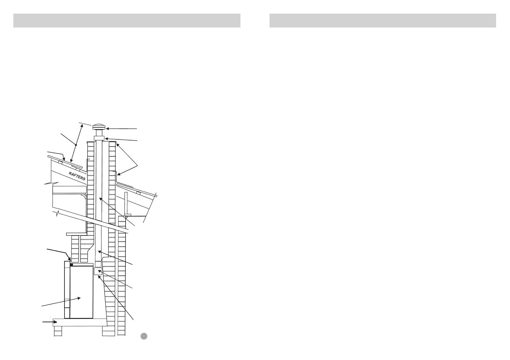
F1417 flue transition rectangular to 100mm round.
F2517 flue spigot is also required.
The flue must be rigid and self-supported. It is a
requirement that the heater has a slip flue
connection and can be removed without any
restrictions.
Ø
Single skin flue.
100mm
Heater
Install heater
onto a solid,
leveled base.
Seal heater
perimeter with
the foam tape
supplied.
Roof cladding
600mm between top of
cowl and nearest part of
roof. (Also refer to AS
5601)
Flue cowl
approved to
AG604
Flue clamp
Flashing
Fit two lengths of vertical flue (1.8m) before fitting
any 45° bends. If bends are used, fit inside of flue
pipe. Use no more than two 45° bends in the total
flue run and maintain at least 250mm of straight
flue pipe between the bends.
Be careful!
Installing a flue on the shortest
wall may subject it to down
draughts or reverse air flows
through the heater which can be
difficult to find a solution to.
Always adopt correct flue design
practices.
In windy locations consider
installation of a powerflue
version heater or at least an anti
down draught cowl to reduce
any flue operation problems.
The heater has been tested and
should operate satisfactorily
with an optimum flue length of
4.5 meters.
Exceeding this length may affect
the stability of the flame pattern
and the operation of the heater.
Contact our technical support
department if any further advice
is required.
An example of an installation with a flue fitted.
(in most cases only a single skin flue is required)
¡Test the operation of the chimney before installing the new heater.
¡Be careful! CANNON heaters are high efficiency products with low flue
gas temperatures (typically 100°C) so if you are replacing an older type
radiant heater with a much higher flue gas temperature (150°C or higher)
make sure of the integrity of the fireplace and chimney before installing
the new CANNON log fire.
¡A solid, levelled and smooth base is required (fill gaps with fibreglass
insulation if necessary).
¡Avoid installing into large volume fireplaces and chimneys and not fitting a
flue. (It is better to install a flue in these applications).
¡We recommend cleaning or sweeping the chimney and fireplace before
the installation of the heater commences.
¡There must be a good seal around the heater, gas piping and electrical
cable rear entry to stop any leakage of combustion products. Do not use
adhesives or silicone sealant, the heater must be able to be easily
removed if necessary.
¡Install a chimney plate and cowl to the chimney opening using weather-
proof mortar to common building practice.
¡Remove any curved firewall that slopes too far forward to the fireplace
opening as it causes restriction to the flue path above the heater flue
outlet.
¡Make sure that the heater is fully commissioned and be certain to conduct
a test of the integrity of the flue operation, taking into account any
influences created by rangehoods, exhaust fans, central heating, etc.
¡To avoid any unnecessary delays and inconvenience to your customer
please contact or Technical Services Department on 1300 727 421 if the
installation is unusual or you have concerns with the installation and/or
heater operation before the installation commences.
¡Any service requests resulting from incorrect installations are not covered
by our warranty conditions and these calls will result in charges, usually
to the end user, so please ensure that the installation and commissioning
has been satisfactorily carried out before calling for any warranty service.
¡Please make sure that your customer is fully instructed on how to operate
the heater.
7
18
11
Installation WITHOUT a flue connected
8
9
28
27
200mm
min.
Flue cowl. Approved to
AG604
100mm
Fasten and seal baffle
plate to top of chimney
with waterproof mortar.
Baffle plate
50mm
clearance
All gaps between heater
and fireplace to be sealed.
All gaps between heater
bottom case and base of
fireplace to be sealed.
3. Switch the control buttons to ‘High flame’ position as indicated in figure 27
and using a spanner adjust the pressure to 0.75 kPa for Natural gas or
2.65 kPa for LPG. (Turn clockwise to increase pressure and anticlockwise
to decrease pressure).
4. Switch the control buttons to ‘Low flame’ position as indicated in figure 28.
Retain spanner in position and using a screwdriver adjust the central screw
control to give a pressure reading of 0.4 kPa for Natural Gas and 1.1 kPa
for LPG. (Turn clockwise to increase pressure and anticlockwise to
decrease pressure).
5. Switch heater off and remove the manometer tube. Tighten pressure test
point by turning the captive screw fully clockwise.
6. Replace plastic cap. Ensure the little lug is positioned towards lower right
hand side to clear the controls.
7. Refit the fascia, making sure not to damage the power cord or switch cable.
8. Follow user instructions to turn on heater.
Operate the heater of HIGH, MEDIUM and LOW settings.
The flame should be stable, no lifting from the burner and the logs should
glow after approximately 15 minutes of operation at HIGH burner.
If the flame is unstable:
?Check that the burner is located correctly.
?Check that the glass front is located correctly and is against the sealing
rope.
?Check that the gas pressure is correctly adjusted.
If the heater still does not operate to specification refer to the troubleshooting
chart on pages 20 & 21, or contact Sampford IXL in your state.
Seal gas pipe and
cable holes with a
suitable removable
material.
17
12
25
Gas control
24
Plastic Cap
Pressure adjustment
(Burner ‘Full on’)
Burner adjustment
(Burner ‘Low flame’)
Pressure test point
with captive screw
Important! To
achieve the
correct visual
flame effect:
On Propane the
gas pressure must
be set at 2.65 kPa
with burner
operating on
maximum setting.
On Natural Gas
the gas pressure
must be set at
0.75 kPa with
burner operating
pressure on
maximum setting.
1. Gas control layout is as indicated in figure 24.
Pressures for ‘Burner full on’ and ‘Burner low flame’ are factory set,
however if pressures need to be checked or adjusted follow the
procedures described below and on the next page.
To check control outlet pressure at burner ‘full on’ and ‘low flame’
positions remove the plastic cap from the regulatior adjustment
location as indicated in figure 25.
Gas pressure sampling point
2. The pressure point is closed with a captive screw. Turn screw 6
revolutions anticlockwise to open the pressure point as indicated on
figure 26 (a) and place manometer tube over the test point as per
figure 26 (b).
(a)
(b)
26
3. To remove the inner glass: see Fig 12.
Loosen off the top horizontal screws only.
Completely remove the two vertical side
clamps. Try not to touch the front surface
of the glass to avoid finger marks. Remove
the glass by gripping each vertical side
and lifting out from the bottom. Place the
glass in a safe position for refit later.
1. Remove the wire mesh grille by gently lifting it upwards and then outwards.
Similarly remove a fitted glass kit by also gently lifting it upwards and then
outwards.
2. Remove 4 M5 screws fixing the fascia assembly to the heater body. Bring the
bottom of the fascia towards you gently to partly disengage it from the body of
the heater. After it has been disengaged gently lift it up vertically to completely
disengage it from the body of the heater. Refer figure 10.
10
17
12
Front Fascia removal
To fully remove the fascia, unclip the switch cable
from the cable connector on the PCB and unclip the
cable from the clipping points on the rear of the
fascia.
11
13
16
DO NOT SEAL WITH SILICON
If using a spacer to compensate for lack of
chimney depth ensure the tape is placed on
the outer rim of the spacer flange. Refer
figure14.
14
13
All gaps between heater case and fireplace are
to be sealed. Seal with foam tape around top
and sides of heater flange. Refer figure 13.
Seal with fibreglass
between bottom of heater
case and base of fireplace.
Sealing the Fascia
22
23
21
Gas connections
1. Push the gas inlet access plate into the heater cabinet and slide the heater into the
fireplace ensuring that the gas inlet pipe is fed through the hole located at the rear
right hand side of the heater at the bottom. Refer to figure 21 and connection
dimensions in figure 23.
2. With heater in position, flanges should be hard against masonry. Secure case flanges
to the masonry. Screw or bolt the flange through the slots provided (figure 22).
3. Connect the gas supply pipe to the copper compression fitting provided (we
recommend using a basin wrench).
Push the gas inlet plate down to its original position and seal with an appropriate easily
removable material. Do not seal with a silicone sealant as the heater must be easily
removable.
Sealing is important as it prevents any leakage of flue products into the room.
Test all connections for gas leaks.
1. The burner is contained within the burner
chamber. Refer figure 15.
2. Carefully unpack the log set. Logs are
numbered as follows:
#1 - Left front log
#2 - Left back log
#3 - Right front log
#4 - Right back log
Position the four individually numbered logs in the following order on the burner head as
shown in figure 16-19. The male locating pins on burner head must engage with
corresponding holes in the individual logs.
a) Place log #1 into the 2 front left pins on the burner
head, ensuring that the charring faces the front.
Refer figure 16.
b) Place log #2 onto the 2 left back pins. Refer figure
17.
c) Place log #3 on single right front pin, ensure fork
locates over log #2. Refer figure 18.
d) Place log #4 on single right back pin, ensure left side
of log rests on depression in #3 log. Refer figure 19.
3. Refit the inner glass, making sure not to over tighten
the screws.
4. Reconnect switch loom to the fascia switch set.
5. Replace the fascia.
6. Connect plug to the wall socket and switch it on.
15
14
The heater is supplied with a flexible power cord with a plug fitted.
A 10 Amp powerpoint (socket) must be located within 1.5m of the heater.
For installations where the powerpoint is located outside of the enclosure, locate
the power cord in the fascia cut out on the left or right hand side as required.
For a power supply connection located inside the enclosure run the power cord
through the cord access located on the rear panel at the lower left hand side by
pushing the cord access plate from the bottom.
The rubber grommet that is fitted over the cord must be located correctly in the
cut out of the cord access plate (see figure 20).
Restore the cord access plate to the original position and seal with an appropriate
removable material, this is especially important when the installation is in a
chimney with no flue fitted to eliminate the possibility of any leakage of flue
products into the room.
A suitable double pole isolation switch must be installed externally for servicing or
emergency shut down of the heater.
All fixed wiring must be installed by a suitably qualified person and comply to the
appropriate electrical wiring rules and gas installation standards.
Electrical Connection
This appliance is designed to operate on 240V AC power supply. Failure to
operate unit at correct supply voltage may created unsafe conditions.
15
Log installation
19
16
17
18
20
  • Page 1 1
  • Page 2 2
  • Page 3 3
  • Page 4 4
  • Page 5 5
  • Page 6 6
  • Page 7 7
  • Page 8 8
  • Page 9 9
  • Page 10 10
  • Page 11 11
  • Page 12 12
  • Page 13 13
  • Page 14 14

Cannon Fitzroy Specification

Category
Water heaters & boilers
Type
Specification
This manual is also suitable for

Cannon Fitzroy is an inbuilt gas heater that combines style with functionality. Designed for use with natural or propane gases, it boasts a 26 MJ/hr gas consumption and 5.98 kW energy output. Its electronic direct spark controller and 3-speed fan ensure efficient and convenient heating. With a 10-year warranty on the heat exchanger, you can trust in its long-lasting performance.

Ask a question and I''ll find the answer in the document

Finding information in a document is now easier with AI