Page is loading ...

1
IMPORTANT:
IMPORTANT:
Go to www.extron.com for the complete
user guide, installation instructions, and
specifications before connecting the
product to the power source.
DTP2 R 212 Series • Setup Guide
This guide provides instructions for an experienced installer to install, set up, and operate the following Extron DTP2 R 212 Series twisted
pair (TP) switching receivers:
• DTP2 R 212 — Twisted pair receiver with a range of up 330 feet (100 M) from the transmitter
• DTP2 R 212 SA — Twisted pair receiver with a range of up 330 feet (100 M) and a built-in audio amplifier
NOTE: For more information on any subject in this guide, see the DTP2 R 212 Series User Guide, available at www.extron.com.
The receivers switch between a local HDMI input and a TP signal from a compatible DTP transmitter. The switching receivers are
compatible with all Extron DTP2 and legacy DTP products. The receiver and a compatible transmitter are rated for a range of up to
330 feet (100 M).
Installation
Step 1 — Mounting
Turn off or disconnect all equipment power sources and mount the DTP2 R 212 Series as required.
Step 2 — Connections and Settings
Rear panel
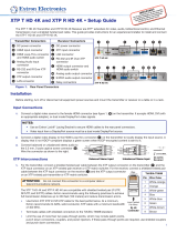
NOTE: Figure 1 is a composite drawing showing the features of all models. Items
F
,
H
, and
I
are present on only one model.
CLASS 2
WIRING
4/8 OHM
L
R
HDMI
Rx GTx
RS-232
DISPLAY
POWER
12V
3.0 A MAX
RS-232
RxTx G
OUTPUT
CVG
10V 50mA
LR
VOL
REMOTE
R
DTP2 R 212 SA
LAN
1
2
Rx GTx
HDMI
RS-232 IR
RxTx
OVER DTP2
INPUTS
SIGLINK
DTP2 IN
OFF
SEND POWER
A BCL G H JIED F KMN
* **
* DTP2 R 212 SA only
DTP2 R 212 only
Figure 1.
DTP2 R 212 SA and DTP2 R 212 Rear Panel
A
HDMI input 1
H
* Volume control port
B
DTP2 input 2 (see page 2)
I
* Volume select switch
C
Over DTP2 connector
J
Remote RS-232 port
D
HDMI output
K
LAN port
E
Audio output
L
Power
F
*Amplified output
M
Send Power switch (see page 3)
G
Display RS-232 port
N
Reset button
A
HDMI input 1 — Plug an HDMI digital video source into the switcher via this HDMI connector. This connector can also
1
accept DVI video with appropriate adapters. See HDMI connectors on page 7 to use the LockIt HDMI Cable Lacing
Bracket™ to secure the connector to the switcher.
NOTE: The maximum HDMI cable length is 4.5 m (15 feet).

2
DTP2 R 212 Series • Setup Guide (Continued)
B
DTP2 input 2 (see figure 1 on page 1) — Connect an STP cable between a compatible Extron DTP transmitting device
SIGLINK
DTP2 IN
RJ-45 and this connector (see TP connectors on page 8 to properly wire the connector and for detailed NOTES).
ATTENTION:
• Do NOT use the receiver to remotely power a legacy DTP unit. Circuit damage to the transmitter WILL result.
• NE PAS utiliser le récepteur pour alimenter à distance un émetteur de la gamme existante DTP. Cette opération
FINIRA par endommager le circuit menant à l’émetteur.
Signal LED indicator — Lights green when the receiver accepts a video signal.
Link LED indicator — Lights yellow when a device is connected and communication is established.
RS-232 IR
Tx TxGRx Rx
OVER DTP2
2
C
Over DTP2 RS-232 and IR port (input 2) — Plug a serial RS-232 signal, a modulated IR signal (up to 40 kHz), or both
into this 3.5 mm, 5-pole captive screw connector for bidirectional RS-232 and IR communication (see RS-232 and IR
connectors on page 6 to wire the connector). RS-232 and IR data can be transmitted simultaneously.
D
HDMI output port — Connect an HDMI cable between this port and an HDMI video display. See HDMI connectors on
page 7 to use the LockIt HDMI Cable Lacing Bracket to secure the connector to the switcher.
NOTE: The maximum HDMI cable length is 4.5 m (15 feet).
E
Audio output port — Connect an audio device such as an audio amplifier or powered speakers to this 5-pole, 3.5 mm
LR
captive screw connector. This connector outputs unamplified, line level audio, whether it is from an analog input to the
transmitter or de-embedded from the transmitter HDMI input (see Analog audio output connector on page 10 to wire the
connectors).
This connector can be tied to the amplied output (SA models) so that the volume varies as the amplied output varies or xed at
0 dB.
LR
4/8 OHM
CLASS
WIRI
NG
F
Amplified output
(DTP2 R 212 SA only) — Connect unpowered, 4-ohm or 8-ohm speakers to this 4-pole 5 mm
captive screw connector to play the amplified stereo audio output.
G
Display RS-232 port
— If desired, connect serial bidirectional RS-232 signals to this 3.5 mm, 5-pole captive screw
RS-232
Tx Rx G
DISPLAY
connector for control of a connected display device via the DTP transmitter. (see RS-232 and IR connectors on page 6 to
wire the connector)
H
Volume port (DTP2 R 212 SA only) — The volume of the amplified audio output can be controlled via a hard-wired
CGV
10V 50mA
potentiometer control, such as the Extron VC 50, the VCM 100 Series devices, and the VCM 200 Series devices. A locally-
constructed device can also be used (see the DTP2 R 212 User Guide for assembly guidelines).
NOTE: The Volume switch (
I
) must be in the Volume Port (down) position for a device connected to this port to
control the volume.
I
Volume switch (DTP2 R 212 SA only) — Set this switch as follows to select how the amplified output volume is controlled.
VOL
RS-232 position (up) — The volume of the amplied audio output can be controlled via the RS-232 port by issuing SIS
commands or the Product Conguration Software.
Volume port position (down) — The volume of the amplied audio output can be controlled via a local control device
connected to the Volume port (H).
J
Remote RS-232 port — Plug a serial RS-232 device into the switcher via this 3.5 mm, 3-pole captive screw connector for
RS-232
Tx G
Rx
remote control of the switcher (see RS-232 and IR connectors on page 6 to wire the connector).
K
LAN port — If desired, for remote control of the networked switcher, connect the switcher to a PC or to an Ethernet LAN via
LAN
this RJ-45 connector.
Act (yellow) LED — The Act LED indicates transmission of data packets on the RJ-45 connector. This LED blinks as the
switcher communicates.
Link (green) LED — The Link LED indicates that the switcher is properly connected to an Ethernet LAN. This LED lights steadily.
L
Power connector and LED — Plug the included external 12 VDC power supply into this 2-pole connector.
POWER
12V
2.0 A MAX

3
M
Send Power toggle switch (see figure 1 on page 1)— In a system with a DTP2 transmitter, set the toggle switch to the Send
OFF
SEND
POWER
Power position (up) on the powered unit to enable sending power to the unpowered unit. Set the toggle switch to the Off
position (down) on the DTP2 unit that is to receive power.
ATTENTION:
• The DTP2 device is configured to output power to DTP2 models only. If connected to a legacy DTP device, set the toggle
switch to the Off position (down). Failure to turn the power off will damage the connected legacy DTP device.
• Le DTP2 est configuré pour fournir une alimentation aux modelèles legacy DTP uniquement. S’il est connecté à un autre
appareil, veuillez positionner l’interrupteur à bascule sur « Off »(down). Si l’interrupteur n’est pas positionné sur off, vous
risquez d’entraîner la défaillance de l’appareil non DTP2 connecté.
NOTES:
• The DTP2 R 212 SA must always be powered locally, but can send power to the connected transmitter.
• The DTP2 R 212 (non SA model) can either receive from or send power to the connected receiver.
N
Switcher Reset button and LED
— Initiates four levels of switcher reset. See the DTP2 R 212 Series User Guide, available
R
at www.extron.com.
Front panel
e
CONFIG
AUTO
SWITCH
A
Figure 2. Front Panel Configuration Port
A
Configuration port
— This USB mini-B port serves a similar communications function as the rear panel Remote port, but it is easier
to access than the rear port after the switching receiver has been installed and cabled.
NOTE: A front panel Configuration port connection and a rear panel Remote port connection can both be active at the same
time. If commands are sent simultaneously to both, the command that reaches the processor first is handled first.
Operation
Front Panel Features
All DTP2 R 212 models share a common front panel (see gure 3).
DTP2 R 212 SERIES
CONFIG
AUTO
SWITCH
INPUTS
OUTPUT
12
SIGNAL
HDCP
INPUTS
1
MODE NORM/AUTO
2
CC
A B D E F
Figure 3. Front Panel Features
A
Power LED
D
Mode button (see page 4)
B
Auto Switch LED
E
Normal/Auto Button
C
Input buttons and LEDs
F
Status LEDs
A
Power LED — Lights when power is applied.
B
Auto switch LED — Lights when the device is in auto switch mode (see Selecting the switch mode on page 4).
C
Input buttons and LEDs — Press and release to select the associated input. The LED indicates the selection.
NOTES:
• The switcher must be in manual switch mode (Auto Switch LED [
B
] unlit) to select an input with these buttons.
• These buttons also select the auto or manual switch mode (see
D
and
E
on page 4 and Selecting the switch mode).

4
DTP2 R 212 Series • Setup Guide (Continued)
D
Mode button (see page 3)— Press and hold to enable toggling between normal and auto switch modes.
E
Normal/Auto Button — Toggles between auto switch and manual mode (see “Selecting the switch mode,” below).
F
Status LEDs (6) —
Signal LEDs (3) — Lights when a signal is detected on the applicable input or the output.
HDCP LEDs (3) — Lights when the HDMI signal is encrypted on the applicable input or the output.
Power
When AC power is applied, the switcher performs a self-test that blinks the front panel LEDs. An error-free power up self-test leaves the
Auto Switch and Input LEDs on or off in the same conguration as they were when power was last removed.
Plug in all system components and turn on the input devices, the connected DTP transmitter, and the output device. Set the input devices
to output video using the operating instructions for those devices. Select an input. The image should appear on the screen.
Switching inputs
1
INPUTS
MODE NORM/AUTO
Press the button.
The LED lights gr
een.
NOTE: The switcher must be in normal (manual) mode.
Select the desired input by pressing the associated input button.
Observe that the LED for the selected input lights.
Selecting the switch mode
NOTE: In the auto-input switching mode that is available from the front panel, the switcher automatically selects the input with a sync
signal present, with input 2 taking priority if both have sync.
Turn auto-input switching mode on and off as follows:
AUTO
SWITCH
1
INPUTS
MODE NORM/AUTO
Press and HOLD
the button.
Release
the button.
Auto Switch
lights (auto)
or goes out
(normal).
Press and release
the button.
3
seconds
1
3
2
5
4
1. Press and hold the Mode (Input 1) button for approximately 3 seconds (
1
)
until the Input 1 LED blinks (
2
).
2.
Release the button (
3
).
3.
As necessary pr
ess and release the Norm/Auto (Input 2) button (
4
).
The Input 1 LED goes off. The Auto Switch LED (
5
) indicates as follows.
Auto mode — Auto Switch lights.
Normal mode — Auto Switch is unlit.
Making Connections
HDMI Connectors
1. Plug the HDMI cable into the panel connection (see
1
, at right).
3
33
11
55
44
22
2. Loosen the HDMI connection mounting screw from the panel enough to allow the LockIt lacing
bracket to be placed over it. The screw does not have to be removed.
3.
Place the LockIt lacing bracket on the scr
ew and against the HDMI connector, then tighten the
screw to secure the bracket.
ATTENTION:
• Do not overtighten the HDMI connector mounting screw. The shield it fastens to is very
thin and can easily be stripped.
• Ne serrez pas trop la vis de montage du connecteur HDMI. Le blindage auquel elle est
attachée est très n et peut facilement être dénudé.
4. Loosely place the included tie wrap around the HDMI connector and the LockIt lacing bracket as
shown.
5. While holding the connector securely against the lacing bracket, use pliers to tighten the tie wrap, then remove any excess length.

5
TP connectors
Both RJ-45 ports, the DTP input port and the LAN (Ethernet) port, use twisted pair cables (see gure 4).
A cable that is wired as T568A at one end
and T568B at the other (Tx and Rx pairs
reversed) is a "crossover" cable.
A cable that is wired the same at both ends is
called a "straight-through" cable, because
no pin/pair assignments are swapped.
12345678
RJ-45
Connector
Inser
t Twisted
Pair Wires
Pins:
Crossover Cable Straight-through Cable
Pin
1
2
3
4
5
6
7
8
Wire color
White-green
Green
White-orange
Blue
White-blue
Orange
White-brown
Brown
Wire color
T568A T568B
End 1 End 2 End 1 End 2
White-orange
Orange
White-green
Blue
White-blue
Green
White-brown
Brown
Pin
1
2
3
4
5
6
7
8
Wire color
White-orange
White-green
Blue
White-blue
White-brown
Brown
Wire color
T568BT568B
White-orange
OrangeOrange
White-green
Blue
White-blue
GreenGreen
White-brown
Brown
Figure 4. RJ-45 Connector and Pinout Tables
Patch (straight) cable —
DTP input 2 port — Shielded twisted pair (STP) (preferred) or unshielded TP for connection to an Extron DTP transmitter or an
XTP matrix switcher.
LAN port — Unshielded twisted pair (UTP) or STP for connection of the LAN port to an Ethernet LAN.
Crossover cable —
LAN port — UTP or STP for direct connection between the switcher and a connected computer.
NOTES:
• Do not use standard telephone cables. Telephone cables do not support Ethernet or Fast Ethernet.
• Do not stretch or bend cables. Transmission errors can occur.
LAN port
The LAN port requires Category (CAT) 3, CAT 5e, or CAT 6a unshielded twisted pair (UTP) or shielded twisted pair (STP) cables, crossover
or patch cables.
The cable used depends on your network speed. The switcher LAN port supports both 10 Mbps (10Base-T — Ethernet) and 100 Mbps
(100Base-T — Fast Ethernet), half-duplex and full-duplex Ethernet connections.
10Base-T Ethernet requires CAT 3 UTP or STP cable at minimum.
100Base-T Fast Ethernet requires CAT 5e UTP or STP cable at minimum.
DTP input port
The DTP input port is compatible with Extron XTP DTP 24 SF/UTP cables or shielded twisted pair (F/UTP, SF/UTP, and S/FTP) cable.
Extron recommends the following practices to achieve full transmission distances up to 330 feet (100 m) and reduce transmission errors.
Use the following Extron XTP DTP 24 SF/UTP cables and connectors for the best performance:
XTP DTP 24/1000 Non-Plenum 1000’ (305 m) spool
22-236-03
XTP DTP 24P/1000 Plenum 1000’ (305 m) spool
22-235-03
XTP DTP 24 Plug Package of 10
101-005-02
NOTE: When using cable in bundles or conduits, consider the following:
• Do not exceed 40% fill capacity in conduits.
• Do not comb the cable for the first 20 meters, where cables are straightened, aligned, and secured in tight bundles.
• Loosely place cables and limit the use of tie wraps or hook and loop fasteners.
• Separate twisted pair cables from AC power cables.

6
68-2986-50 Rev. A
04 20
© 2020 Extron Electronics — All rights reserved. www.extron.com
All trademarks mentioned are the property of their respective owners.
For information on safety guidelines, regulatory compliances, EMI/EMF compatibility, accessibility, and related topics, see the
Extron Safety and Regulatory Compliance Guide on the Extron website.
ATTENTION:
• Do not connect this device to a computer data or telecommunications network.
• Ne connectez pas cet appareil à un réseau de télécommunications ou de données informatiques.
• Do not use Extron UTP23SF-4 Enhanced Skew-Free AV UTP cable or STP201 cable to link the matrix switcher to Extron DTP
products, XTP matrix switchers, or HDBaseT-enabled devices.
• N'utilisez pas le câble AV Skew-Free UTP version améliorée UTP23SF-4 ou le câble STP201 pour relier la grille de commutation à
des produits DTP, à des grilles de commutation XTP ou à des appareils équipés HDBaseT Extron.
• To ensure FCC Class A and CE compliance, STP cables and STP connectors are required.
• Afin de s’assurer de la compatibilité entre FCC ClasseA et CE, les câbles STP et les connecteurs STP sont nécessaires.
Analog audio output connector
Figure 5 shows how to wire the audio output connector. Use the supplied tie-wrap to strap the cable to the extended tail of the connector.
Unbalanced Stereo Output Balanced Stereo Output
Do not tin the wires!
Tip
No Ground Here
No Ground Here
Tip
LR
Sleeves
Tip
Ring
Tip
Ring
LR
Sleeves
Figure 5. Audio Output Connector Wiring
ATTENTION:
• For unbalanced audio, connect the sleeves to the ground contact. DO NOT connect the sleeves to the negative (-) contacts.
• Pour l’audio asymétrique, connectez les manchons au contact au sol. Ne PAS connecter les manchons aux contacts négatifs (–).
NOTES:
• The length of exposed wires is important. The ideal length is 3/16 inch (5 mm).
• If the stripped section of wire is longer than 3/16 inch, the exposed wires may touch, causing a short circuit.
• If the stripped section of wire is shorter than 3/16 inch, wires can be easily pulled out even if tightly fastened.
• Do not tin the leads. Tinned wires are not as secure in the connector and could be pulled out.
RS-232 and IR connectors
Figure 6 shows how to wire the RS-232 and IR connectors.
Tx/Rx
Pins
Rx Tx
Tx Rx
Gnd
Gnd
RS-232 Device
IR Device
RS-232 IR
Tx Rx Tx RxG
TxGnd
RS-232 Device
Rx
OVER TP
Rx GTx
RS-232
DISPLAY
TxGnd
RS-232 Device
Rx
Rx GTx
RS-232
Figure 6. RS-232 and IR Connector Wiring
NOTE: The length of exposed wires is important (see the audio connectors NOTES above for more information).
1
/