
Invacare® Dragon
Invacare® Tiger
SERVICE INSTRUCTIONS
These instructions contain information on:
Inspection work
Repair work
Issue: 21/04/10

Mobitec Mobilitätshilfen GmbH
Herzog Odilostrasse 101
A-5310 Mondsee
Austria
: +43 6232 55 35 0
Fax: +43 6232 55 35 4
WWW: www.mobitec-austria.com
Invacare® n.v.
Autobaan 22
B-8210 Loppem (Brugge)
Belgium
: +32 (0)50 83 10 10
Fax: +32 (0)50 83 10 11
WWW: www.invacare.be
Mobitec Rehab AG
Benkenstraße 260
CH-4108 Witterswil
Switzerland
: +41 (0)61 48 77 08 0
Fax: +41 (0)61 48 77 08 1
WWW: www.mobitec-rehab.ch
Invacare Aquatec
Alemannenstraße 10
88316 Isny
Deutschland
+49 (0)75 62 7 00 0
Fax +49 (0)75 62 7 00 66
WWW: www.invacare-aquatec.de
Invacare® A/S
Sdr. Ringvej 37
DK-2605 Brøndby
Danmark
(Kundeservice): +45 (0)36 90 00 00
Fax (Kundeservice): +45 (0)36 90 00 01
WWW: www.invacare.dk
Invacare® SA
c/ Areny, s/n
Polígon Industrial de Celrà
E-17460 Celrà (Girona)
ESPAÑA
: +34 (0)972 49 32 00
Fax: +34 (0)972 49 32 20
WWW: www.invacare.es
Invacare® Poirier SAS
Route de St Roch
F-37230 Fondettes
France
: +33 (0)247 62 64 66
Fax: +33 (0)247 42 12 24
WWW: www.invacare.fr
Invacare® Ltd
Pencoed Technology Park
Pencoed
Bridgend CF35 5HZ
United Kingdom
(Customer Service): +44 (0)1656 776 222
Fax (Customer Service): +44 (0)1656 776 220
WWW: www.invacare.co.uk
2

Invacare Mecc San s.r.l.
Via Dei Pini, 62
I - 36016 Thiene (VI)
ITALIA
: +39 0445 38 00 59
Fax: +39 0445 38 00 34
WWW: www.invacare.it
Invacare Ireland Ltd.
Unit 5 Seatown Business Campus
Seatown Rd, Swords
County Dublin
Ireland
: +353 18 10 70 84
Fax: +353 18 10 70 85
WWW: www.invacare.ie
Invacare® AS
Grensesvingen 9
Postboks 6230
Etterstad
N-0603 Oslo
Norge
(Kundeservice): +47 (0)22 57 95 00
Fax (Kundeservice): +47 (0)22 57 95 01
WWW: www.invacare.no
Invacare® B.V.
Celsiusstraat 46
NL-6716 BZ Ede
Nederland
: +31 (0)318 69 57 57
Fax: +31 (0)318 69 57 58
WWW: www.invacare.nl
Invacare Portugal, Lda
Rua Estrada Velha, 949
P-4465-784 Leça do Balio
Portugal
: +351 225 1059 46
: +351 225 1059 47
Fax: +351 225 1057 39
WWW: www.invacare.pt
3

Återförsäljare:
Invacare® AB
Fagerstagatan 9
S-163 91 Spånga
Sverige
Tillverkare:
Invacare® Deutschland GmbH
Kleiststraße 49
D-32457 Porta Westfalica
Deutschland
(Kundtjänst): +46 (0)8 761 70 90
Fax (Kundtjänst): +46 (0)8 761 81 08
WWW: www.invacare.se
MÖLNDAL
: +46 (0)31 86 36 00
Fax: +46 (0)31 86 36 06
LANDSKRONA
: +46 (0)418 285 40
Fax: +46 (0)418 180 89
OSKARSHAMN
: +46 (0)491 101 40
Fax: +46 (0)491 101 80
4

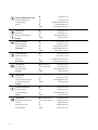
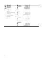
Table of Contents
Chapter Page
TABLE OF CONTENTS 5
1 INTRODUCTION 7
1.1 General information 7
1.2 Notes on transport 7
1.3 Definition and representation of information and safety information in this manual 8
1.4 Hazard symbols and symbols used 9
1.5 Images in this manual 10
2 SAFETY AND FITTING INSTRUCTIONS 11
2.1 Before any inspection or repair work 11
2.2 Personal safety equipment 11
2.3 General safety information and information about fitting / removal 11
3 TIGHTENING TORQUES 13
4 ARRANGEMENT OF THE ASSEMBLY GROUPS AND COMPONENTS 14
5 SERVICE PLAN (1X ANNUALLY) 15
6 OPERATIONAL FAULTS 17
6.1 Operational faults on a wheelchair fitted with Shark electronics 17
6.1.1 Diagnosis of actuation disorders 17
6.1.2 Shark error codes and diagnostic codes 19
6.2 Troubleshooting the Tornado with ACS 21
6.2.1 Diagnosing driving faults 21
6.2.2 Diagnosing problems with electric actuators 23
6.2.3 REM24 Error Codes and Diagnostic Codes 24
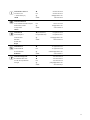
7 REPAIR WORK 26
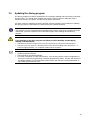
7.1 General warning information on installation work 26
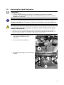
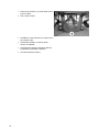
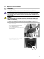
7.2 Replacing the motor 26
5

7.3 Replacing the Shark Electronics 31
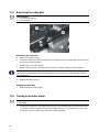
7.4 Updating the driving program 33
7.5 Changing the batteries 34
7.5.1 Removing the batteries 35
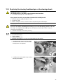
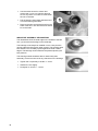
7.5.2 How to handle damaged batteries correctly 36
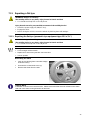
7.6 Checking and replacing the main fuse 37
7.7 Checking the cables 39
7.8 Replacing the Shark Remote 41
7.9 Replacing the ACS Remote 43
7.10 Replacing the steering head bearings on the steering wheels 45
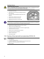
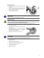
7.11 Repairing a flat tyre 47
7.11.1 Repairing the flat tyre (pneumatic tyre equipment type 12½ x 2¼") 47
7.11.2 Repairing a flat tyre (pneumatic tyre equipment type 220/120 x 50) 48
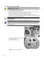
7.12 Replacing a drive wheel 50
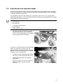
7.13 Adjusting the seat angle/seat height 51
7.13.1 Adjustment tables 53
7.14 Replacing the safety belt 56
7.15 Testing an actuator motor 56
6

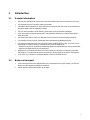
1 Introduction
1.1 General information
• Service and maintenance work must be carried out taking this service manual into account.
• It is imperative that you observe safety information.
• Information about operation or about general maintenance and care work on the mobility aid
should be taken from the operating manual.
• You can find information about ordering spare parts in the spare parts catalogue.
• Only use original Invacare® spare parts. The guarantee will become invalid if other spare
parts are used!
• We reserve the right to make any alterations on the grounds of technical improvements.
• The mobility aid may only be maintained and overhauled by qualified personnel.
• The minimum requirement for service technicians is suitable training, such as in the cycle or
orthopaedic mechanics fields, or sufficiently long-term job experience.
- Experience in the use of electrical measuring equipment (multimeters) is also a requirement.
- Special Invacare® training is recommended.
• Alterations to the mobility aid which occur as a result of incorrectly or improperly executed
maintenance or overhaul work lead to the exclusion of all liability on the side of INVACARE.
• If you have any problems or questions please contact Invacare® Service.
1.2 Notes on transport
• If the mobility aid has to be shipped back to the manufacturer for major repairs, you should
always use the original packaging for transport.
• Please attach a precise description of the fault.
7

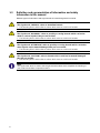
1.3 Definition and representation of information and safety
information in this manual
Different types of information and signal words are used throughout this manual.
HAZARD!
The signal word "HAZARD!" refers to immediate hazards.
• The following lines in italics refer to actions which serve to avoid such hazards.
WARNING!
The signal word "WARNING!" refers to possibly-occurring hazards which can lead to
death or serious injuries if they are not avoided.
• The following lines in italics refer to actions which serve to avoid such hazards.
ATTENTION!
The signal word "ATTENTION!" refers to possibly-occurring hazards which can lead to
minor injuries and/or material damage if they are not avoided.
• The following lines in italics refer to actions which serve to avoid such hazards.
CAUTION!
The signal word "CAUTION!" refers to hazards which could lead to material damage if
they are not avoided.
• The following lines in italics refer to actions which serve to avoid such hazards.
Note
The signal word "Note" is used to denote general information which simplifies the handling of
your product and refers to special functions.
8

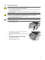
1.4 Hazard symbols and symbols used
Different types of hazard symbols and symbols are used throughout this manual.
General hazards
This symbol warns you of general hazards!
• Always follow the instructions to avoid injury to the user or damage to the product!
BURN HAZARD!
This symbol warns you of the danger of chemical burns, for example due to the discharge
of battery acids!
• Always follow the instructions to avoid injury to the user or damage to the product!
DANGER OF CRUSHING!
This symbol warns you of crushing hazards due to inattentive working with heavy
components.
• Always follow the instructions to avoid injury to the user or damage to the product!
EXPLOSION HAZARD!
This symbol warns you of an explosion hazard, which can be caused by excessive tyre
pressure in a pneumatic tyre.
• Always follow the instructions to avoid injury to the user or damage to the product!
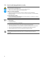
Wear safety shoes
The symbol refers to the requirement for wearing safety shoes.
• Wear standardised safety shoes during all work.
Wear eye protection
This symbol refers to the requirement for wearing eye protection, for example when
working with batteries.
• Wear eye protection when this symbol is shown.
Wear safety gloves
This symbol refers to the requirement for wearing safety gloves, for example when
working with batteries.
• Wear safety gloves when this symbol is shown.
Note
This symbol identifies general information which is intended to simplify working with your product
and which refers to special functions.
Requirements:
• This symbol identifies a list of various tools, components and items which you will need in
order to carry out certain work. Please do not attempt to carry out the work if you do not
have the listed tools available.
Always dispose used or damaged batteries correctly
The symbol refers to information for the correct disposal of used or damaged batteries.
9

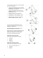
1.5 Images in this manual
The detailed images in this manual are given digits to identify various components. Component
numbers in text and operational instructions always relate to the image directly above.
10

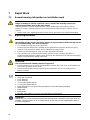
2 Safety and fitting instructions
These safety instructions are intended to prevent accidents at work, and it is imperative that they
are observed.
2.1 Before any inspection or repair work
• Read and observe this repair manual and the associated operating manual!
• Observe the minimum requirements for carrying out the work (see chapter entitled „General
information)!
2.2 Personal safety equipment
Safety shoes
The mobility device, and some of its components, are very heavy. These parts can result
in injuries to the feet if they are allowed to drop.
• Wear standardised safety shoes during all work.
Eye protection
It is possible that battery acid can be discharged when working on defective batteries or
when handling batteries improperly.
• Always wear eye protection when working on any defective or possibly defective batteries.
Safety gloves
It is possible that battery acid can be discharged when working on defective batteries or
when handling batteries improperly.
• Always wear acid-proof safety gloves when working on any defective or possibly defective
batteries.
2.3 General safety information and information about fitting / removal
WARNING: Danger of crushing!
Various components such as the drive unit, batteries, seat etc are very heavy. This results
in injury hazards to your hands!
• Please note the high weight of some components! This applies especially to the removal of
drive units, batteries and the seat.
WARNING!
Injury hazard if the vehicle starts moving unintentionally during repair work!
• Switch the power supply off (ON/OFF key)!
• Engage the drive!
• Before raising the vehicle, secure the wheels by blocking them with wedges!
ATTENTION!
Fire and burn hazard due to electrical short-circuit!
• The mobility device must be completely switched off before removal of voltage-carrying
components! To do this, remove the batteries.
• Avoid short-circuiting the contacts when carrying out measurements on voltage-carrying
components!
11

ATTENTION!
Injury hazard and danger of damage to vehicle due to improper or incomplete
maintenance work!
• Use only undamaged tools in good condition.
• Some moving parts are mounted in sockets with PTFE coating (Teflon™). Never grease
these sockets!
• Never use "normal" nuts instead of self-locking nuts.
• Always use correctly-dimensioned washers and spacers
• When reassembling, always replace any cable ties which were cut during dismantling.
• After completing your work / before renewed start-up of the mobility device, check all
connections for tight fitting.
• After completing your work / before renewed start-up of the mobility device, check all parts for
correct locking.
• Only operate the vehicle with the approved tyre pressures (see technical data).
• Check all electrical components for correct function. Please note that incorrect polarity can
result in damage to the electronics.
• Always carry out a trial run at the end of your work.
Note
Mark all current settings for the mobility aid (seat, armrests, backrest etc.), and the associated
cable connecting plugs, before dismantling. This makes reassembly easier.
All plugs are fitted with mechanical safety devices which prevent release of the connecting plugs
during operation. To release the connecting plugs the safety devices must be pressed in. When
reassembling ensure that these safety devices are correctly engaged.
WARNING!
Any changes to the drive program can affect the driving characteristics and the tipping
stability of the vehicle!
• Changes to the drive program may only be carried out by trained Invacare® specialist
dealers!
• Invacare® supplies all mobility aids with a standard drive program ex-works. Invacare® can
only give a warranty for safe vehicle driving behaviour - especially tipping stability - for this
standard drive program!
12

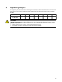
3 Tightening torques
The tightening torques stated in the following list are based on the thread diameter for the nuts and
bolts for which no specific values have been determined. All values assume dry and de-greased
threads.
Thread
M4 M5 M6 M8 M10 M12 M14 M16
Tightening torque
in Nm ±10%
3 Nm 6 Nm 10 Nm 25 Nm 49 Nm 80 Nm 120 Nm 180 Nm
CAUTION!
Damage can be caused to the mobility device due to improperly tightened screws, nuts or
plastic connections.
• Always tighten screws, nuts etc to the stated tightening torque.
• Only tighten screws or nuts which are not listed here fingertight.
13

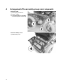
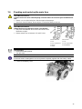
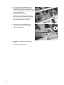
4 Arrangement of the assembly groups and components
Under the seat:
1) Decoupling mechanism
2) Power module
3) Perforated plates for adjusting
the seat height and seat angle
Under the battery cover
4) Main battery fuse
14

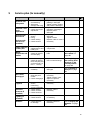
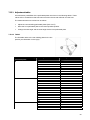
5 Service plan (1x annually)
Component Check Action Notes
Armrests and
side panels
• Armrest damage
and fastening
• Side panel
damage and fixing
• Tighten screws, replace
padding if damaged
• Tighten screws, replace
side panels if damaged
Seat unit / seat
angle
adjustment
• Cushion
• Check seat angle
adjustment
• Replace covers /
upholstery if damaged
• Replace parts if
damaged
Backrest unit
mechanical
Backrest unit
electrical (if
installed)
• Damage and
seams
• Fixing
• Check cabling
• Check function
• Replace parts if
damaged
• Tighten screws
• Replace cable or motor if
necessary
Frame (chassis)
/ battery box
• Check fixings,
welded seams and
battery box
• Tighten screws, replace
components
Wheel
suspension and
wheels
• Check drive
wheels for tight fit
and side play
• Adjust, replace wheel
hubs
See "
Replacing a
drive wheel
" on
page
50
• Check steering
wheels for tight fit,
float, side play and
correct torque (15
Nm +/- 1.5 Nm)
• Replace wheels, wheel
fork or wheel bearings
See "Replacing
the steering head
bearings on the
steering wheels
"
on page
45
• Pneumatic tyres (if
available)
• Repair or replace if
damaged
See "Repairing a
flat tyre
" on page
47
Drive units,
disengager
• Check functions in
drive and push
modes
• Check disengager
• Replace motor if
necessary
• Tighten screws / nuts,
adjust or replace if
necessary
Legrests
• Check welded
seams,
interlocking,
screws, footplates
• Tighten, replace if
necessary
Electrical
footrests (if
installed)
• Check cabling
• Check contacts
• Check functions
• Replace cable if
necessary
Lighting (if
installed)
• Check cabling
• Check function
• Replace bulbs or cables
if necessary
Batteries
• Check batteries
for damage
• Replace batteries if
necessary
See "Changing the
batteries
" on page
34
15

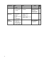
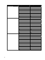
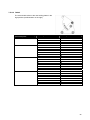
Component Check Action Notes
• Check battery
charge
• Charge batteries
See User Manual
• Check contacts
and terminals for
corrosion
• Clean contacts and
terminals
See "Changing the
batteries
" on page
34 for safety
information when
handling batteries
Remote /
electronics
• Remote,
status display
blinking
• Fixing
• Cable, connecting
plug
• Joystick function
• Power supply
• Evaluate flash code
• Tighten, replace
• Replace
• Replace joystick
• Replace cable, connector
plug or console
Driving
Programme
• Check the
programme
version of the
driving electronics.
Is there a newer
version available?
• Update the software.
See "Updating the
driving program
"
on page
33
16

6 Operational Faults
6.1 Operational faults on a wheelchair fitted with Shark electronics
Please proceed as follows in the event of operational faults:
• First of all analyse the possible cause of the disorder on the basis of the following tables.
• Check the status display on the remote. Analyse the flashing error code.
• Carry out the necessary checks and repairs as recommended in the following table.
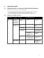
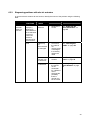
6.1.1 Diagnosis of actuation disorders
PROBLEM
OTHER
SYMPTOMS
POSSIBLE
CAUSE
• SOLUTION
DOCUMENTATION
Wheelchair
will not start
up
Status display on
the remote
illuminated as
normal and does
not indicate a
disorder code
Actuation motors
may be
disengaged
• Clutch in actuation
motors
See operating
instructions
Status display on
the remote is not
illuminated
Batteries may be
faulty
• Replace the batteries
See "
Changing the
batteries
" on page
34
Batteries may be
almost empty
• Charge batteries
See User Manual
Power supply to
the remote may
be interrupted
• Check the main fuse
See "
Checking and
replacing the main
fuse
" on page 37
• Check the cable
between the
modules for any
loose connections or
damage
Siehe "
Checking
the cables
" on
page
39
Remote may be
faulty
• Change the remote
on the wheelchair to
be able to exclude
the remote being the
cause of the fault.
See "
Replacing the
Shark Remote
" on
page
41
Status display on
remote flashing
Various causes
• Analyse error code
See "
Shark error
codes and
diagnostic codes
"
on page
19
17

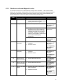
PROBLEM
OTHER
SYMPTOMS
POSSIBLE
CAUSE
• SOLUTION
DOCUMENTATION
Wheelchair
jerky in
drive
operation
None
Batteries may be
faulty (instable
voltage)
• Replace the batteries
See "
Changing the
batteries
" on page
34
Actuation
motor(s) may be
faulty
• Replace motor(s)
Siehe "
Replacing
the motor
" on page
26
Batteries
not being
charged
None Batteries may be
faulty
• Replace batteries
See "Changing the
batteries
" on page
34
LEDs flashing on
charger
Charger may be
faulty
• Replace charger
See operating
instructions for
battery charger
Wheelchair
drives too
slowly
None
Batteries may be
faulty
• Replace batteries
See "Changing the
batteries
" on page
34
18

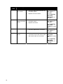
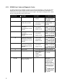
6.1.2 Shark error codes and diagnostic codes
The actuation electronics can automatically remedy certain disorders. In this case the status
display will stop flashing. Please switch the remote on and off several times. Please wait about 5
seconds every time before switching the remote on again. If the error is not remedied by this,
please diagnose the cause on the basis on the following flashing codes.
FLASHING
CODE
Meaning Solution FLASHING CODE
1
Operational error
• Please ensure that the joystick is in
neutral central position (simply release
joystick) and switch on again.
2
Battery error
• Check battery and power cable.
See "Checking
the cables
" on
page
39
• Charge batteries. If you switch the
wheelchair off for a few minutes the
batteries are often able to re-charge
sufficiently to enable a short journey.
You should, however, only use this
solution in an emergency as this leads
to the batteries discharging
excessively.
See operating
instructions
• Replace the batteries
See "
Changing
the batteries
" on
page
34
3
Error on the left
motor (M2)
• Check the motor cable and U-
connector.
• Check the motor.
See "
Checking
the cables
" on
page
39
See "Replacing
the motor
" on
page
26
4
Error on the right
motor (M1)
• Check the motor cable and U-
connector.
• Check the motor.
See "
Checking
the cables
" on
page
39
See "Replacing
the motor
" on
page
26
5
Fault on the left
(M2) motor brake
• Check cable and connector.
See "
Checking
the cables
" on
page
39
6
Fault on the right
(M1) motor brake
• Check cable and connector.
See "
Checking
the cables
" on
page
39
7
Fault on the Shark
remote
• Check the bus cable on the remote
and U-connector.
• Replace the remote.
See "
Checking
the cables
" on
page
39
See "Replacing
the Shark
Remote
" on page
41
19

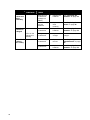
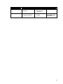
Meaning Solution FLASHING CODE
FLASHING
CODE
8
Fault on Shark
main module
• Check all cables and connectors on
the Shark system.
• Replace the main module.
See "Checking
the cables
" on
page
39
See "Replacing
the Shark
Electronics
" on
page
31
9
Communication
error on the Shark
system
• Check all cables and connectors on
the Shark system.
• Replace the remote.
See "
Checking
the cables
" on
page
39
See "Replacing
the Shark
Remote
" on page
41
10
Unknown error
• Check all cables and U-connectors.
See "
Checking
the cables
" on
page
39
11
Incompatible
remote
• An incorrect remote has been
connected. Ensure that main module
and remote code are concordant.
See "
Replacing
the Shark
Remote
" on page
41
See "Replacing
the Shark
Electronics
" on
page
31
20
Page is loading ...
Page is loading ...
Page is loading ...
Page is loading ...
Page is loading ...
Page is loading ...
Page is loading ...
Page is loading ...
Page is loading ...
Page is loading ...
Page is loading ...
Page is loading ...
Page is loading ...
Page is loading ...
Page is loading ...
Page is loading ...
Page is loading ...
Page is loading ...
Page is loading ...
Page is loading ...
Page is loading ...
Page is loading ...
Page is loading ...
Page is loading ...
Page is loading ...
Page is loading ...
Page is loading ...
Page is loading ...
Page is loading ...
Page is loading ...
Page is loading ...
Page is loading ...
Page is loading ...
Page is loading ...
Page is loading ...
Page is loading ...
-
 1
1
-
 2
2
-
 3
3
-
 4
4
-
 5
5
-
 6
6
-
 7
7
-
 8
8
-
 9
9
-
 10
10
-
 11
11
-
 12
12
-
 13
13
-
 14
14
-
 15
15
-
 16
16
-
 17
17
-
 18
18
-
 19
19
-
 20
20
-
 21
21
-
 22
22
-
 23
23
-
 24
24
-
 25
25
-
 26
26
-
 27
27
-
 28
28
-
 29
29
-
 30
30
-
 31
31
-
 32
32
-
 33
33
-
 34
34
-
 35
35
-
 36
36
-
 37
37
-
 38
38
-
 39
39
-
 40
40
-
 41
41
-
 42
42
-
 43
43
-
 44
44
-
 45
45
-
 46
46
-
 47
47
-
 48
48
-
 49
49
-
 50
50
-
 51
51
-
 52
52
-
 53
53
-
 54
54
-
 55
55
-
 56
56


Invacare Dragon User manual
- Type
- User manual
- This manual is also suitable for
Ask a question and I''ll find the answer in the document
Finding information in a document is now easier with AI
Related papers
-
Invacare TORNADO User manual
-
-
Invacare Dragon Service Instructions Manual
-
-
-
-
Invacare Fox User manual
-
Invacare Spectra XTR User manual
-
-
Other documents
-
E-Collar Technologies E-Collar Technologies FE-560 Dog Collar Battery Operating instructions
-
 Golden Technologies Compass Sport User manual
-
Dynamic DX User manual
-
Rascal 320 Owner's manual
-
 Merits P326A Vision Sport Owner's manual
-
 Arden Medical Urias Air Splints Operating instructions
-
Wells Manufacturing Splint-Form2000 User manual
-
 ARCHITETTURA SONORA SHARK-SUB User manual
-
Aquatec Beluga Assembly Instructions


