Page is loading ...

Invacare® Bora / Spectra XTR
SERVICE MANUAL
These instructions contain information about:
testing work
repair work
Edition:02.06.09

Mobitec Mobilitätshilfen GmbH
Herzog Odilostrasse 101
A-5310 Mondsee
Austria
+43 - 6232 - 55 35 0
Fax: +43 - 6232 - 55 35 4
WWW: www.mobitec-austria.com
Invacare® n.v.
Autobaan 22
B-8210 Loppem (Brugge)
Belgium
+32 - (0)50 - 83 10 10
Fax: +32 - (0) 50 - 83 10 11
WWW: www.invacare.be
Mobitec Rehab AG
Benkenstraße 260
CH-4108 Witterswil
Switzerland
+41 - (0)61 - 48 77 08 0
Fax: +41 - (0)61 - 48 77 08 1
WWW: www.mobitec-rehab.ch
Invacare Aquatec
Alemannenstraße 10
88316 Isny
Deutschland
0 75 62 / 7 00 - 251
Fax 08 00 / 6 73 81 72
WWW: www.invacare-aquatec.de
Invacare® A/S
Sdr. Ringvej 39
DK-2605 Brøndby
Danmark
(Kundeservice): +45 - (0)36 - 90 00 00
Fax (Kundeservice): +45 - (0)36 - 90 00 01
WWW: www.invacare.dk
Invacare® SA
c/ Areny, s/n
Poligon Industrial de Celrà
17460 Celrà (Girona)
ESPAÑA
: +34 - (0)972 - 49 32 00
Fax: +34 - (0) 972 - 49 32 20
WWW: www.invacare.es
Invacare® Poirier SAS
Route de St Roch
F-37230 Fondettes
France
: +33 - (0)247 - 62 64 66
Fax: +33 - (0)247 - 42 12 24
WWW: www.invacare.fr
Invacare® Ltd
South Road
Bridgend Industrial Estate
Mid Glamorgan - CF31-3PY
United Kingdom
(Customer Service): +44 - (0)1656 - 664 321
Fax (Customer Service): +44 - (0)1656 - 667 532
WWW: www.invacare.co.uk
Invacare Mecc San s.r.l.
Via Dei Pini, 62
I - 36016 Thiene (VI)
ITALIA
+39 - 0445 - 38 00 59
Fax: +39 - 0445 - 38 00 34
WWW: www.invacare.it
Invacare Ireland Ltd.
Unit 5 Seatown Business Campus
Seatown Rd, Swords
County Dublin
Ireland
+353 - 18 10 70 84
Fax: +353 - 18 10 70 85
Invacare® AS
Grensesvingen 9
Postboks 6230
N-0603 Oslo
Norge
(Kundeservice): +47 - (0) 22 57 95 10
Fax (Kundeservice): +47 - (0)22 57 95 01
WWW: www.invacare.no
Invacare® B.V.
Celsiusstraat 46
NL-6716 BZ Ede
The Netherlands
: +31 - (0)318 - 69 57 57
Fax: +31 - (0) 318 - 69 57 58
WWW: www.invacare.nl
Invacare® PORTUGAL Lda
Rua Senhora de Campanhã 105
P-4369-001 Porto
PORTUGAL
: +351-225105946
Fax: +351-225105739
WWW: www.invacare.pt

Återförsäljare:
Invacare® AB
Fagerstagatan 9
S-163 91 Spånga
Sverige
Tillverkare:
Invacare Deutschland GmbH
Kleiststraße 49
D-32457 Porta Westfalica
Deutschland
(Kundtjänst): +46 - (0) 8 761 70 90
Fax (Kundtjänst): +46 - (0) 8 761 81 08
WWW: www.invacare.se
MÖLNDAL
+46 - (0) 31 – 86 36 00
Fax: +46 - (0) 31 – 86 36 06
LANDSKRONA
+46 - (0) 418 – 285 40
Fax: +46 - (0) 418 – 180 89
OSKARSHAMN
+46 - (0) 491 – 101 40
Fax: +46 - (0) 491 – 101 80

Contents
Chapter Page
1 Introduction 6
1.1 General information ..................................................................................................................6
1.2 Notes on transport ....................................................................................................................6
1.3 Important symbols in this manual ...........................................................................................6
2 Safety and fitting instructions 8
2.1 Before any inspection or repair work......................................................................................8
2.2 General safety information and information about fitting / removal....................................8
3 Tightening torques 9
4 Layout of components and componentry 10
4.1 Overview...................................................................................................................................10
4.2 Electronics modules ...............................................................................................................11
4.2.1 ACS I 60A electronics module......................................................................................12
4.2.2 ACS II 70A electronics module.....................................................................................12
4.2.3 VR2 electronics module................................................................................................12
4.2.4 Shark electronics module .............................................................................................13
4.2.4.1 Shark with 4-pole DCI..............................................................................................13
4.2.4.2 Shark with DCI 12-pole............................................................................................13
4.2.5 ACT actuator module....................................................................................................13
4.2.5.1 ACT 2 actuator module............................................................................................13
4.2.5.2 ACT 4 actuator module............................................................................................13
4.2.6 Lighting PCB.................................................................................................................13
5 Maintenance plan (1x annually) 14
6 Operational faults 16
6.1 Drive fault diagnosis ...............................................................................................................16
6.2 REM24 remote: Error codes and diagnostic codes .............................................................18
6.3 VR2 remote: Error codes and diagnostic codes ..................................................................18
6.4 Shark II remote Error codes and diagnostic codes .............................................................20
7 Repair work 21
7.1 General warning information about fitting work ..................................................................21
7.2 Replacing drive components .................................................................................................21
7.2.1 Replacing the complete drive unit ................................................................................22
7.2.2 Replacing the motor......................................................................................................23
7.2.3 Replacing the jaw clutch...............................................................................................23
7.2.4 Replace carbon brushes...............................................................................................24
7.3 Replacing the electronics.......................................................................................................26
7.4 Updating software ...................................................................................................................28
7.5 Replacing batteries .................................................................................................................29
7.5.1 Removing the battery cases .........................................................................................29
7.5.2 Removing the batteries.................................................................................................30
7.5.3 Correct handling of damaged batteries ........................................................................33
7.6 Checking and replacing the main fuse..................................................................................33
7.7 Checking the cable..................................................................................................................36
7.8 Differences when replacing the REM24 remote ...................................................................38
7.9 Replacing the steering head bearings on the steering wheels ..........................................39
7.10 Repairing punctures................................................................................................................42
7.10.1 Repairing punctures (wheel size 3.00-8").....................................................................42
7.10.2 Repairing punctures (wheel size 280/250-4)................................................................43
7.11 Replacing a drive wheel..........................................................................................................45
7.12 Checking an adjusting motor.................................................................................................47
7.13 Replacing the seat tilting........................................................................................................47
8 Adjusting the seat depth to the user's seating position 50

8.1 Standard seat...........................................................................................................................50
8.2 Fixed seat .................................................................................................................................52
8.3 Flex-II seat ................................................................................................................................52
9 Replacing the holding strap 54
9.1 Standard seat & Flex II............................................................................................................54
9.2 Fixed seat unit .........................................................................................................................55

1 Introduction
1.1 General information
• Service and maintenance work must be carried out taking this service manual into account.
• It is imperative that you observe safety information.
• Information about operation or about general maintenance and care work on the mobility
device should be taken from the operating manual.
• You can find information about ordering spare parts in the spare parts catalogue.
• Only use original Invacare® spare parts. The guarantee will become invalid if other spare parts
are used!
• We reserve the right to make any alterations on the grounds of technical improvements.
• The mobility device may only be maintained and overhauled by qualified personnel.
• The minimum requirement for service technicians is suitable training, such as in the cycle or
orthopaedic mechanics fields, or sufficiently long-term job experience.
- Experience in the use of electrical measuring equipment (multimeters) is also a requirement.
- Special Invacare training is recommended.
• Alterations to the mobility device which occur as a result of incorrectly or improperly executed
maintenance or overhaul work lead to the exclusion of all liability on the side of INVACARE.
• If you have any problems or questions please contact Invacare Service.
•
1.2 Notes on transport
• If the mobility device has to be shipped back to the manufacturer for major repairs, you should
always use the original packaging for transport.
• You must include a precise fault description.
1.3 Important symbols in this manual
WARNING!
This symbol warns you of danger!
• Always follow the instructions to avoid injury to the user or damage to the product!
EXPLOSION HAZARD!
This symbol warns you of an explosion hazard, which can be caused by excessive tyre
pressure in a pneumatic tyre!
• Always follow the instructions to avoid injury to the user or damage to the product!
BURN HAZARD!
This symbol warns against chemical burns, for example due to the discharge of battery
acids!
• Always follow the instructions to avoid injury to the user or damage to the product!
NOTE:
This symbol identifies general information which is intended to simplify working with your product
and which refers to special functions.

Requirements:
• This symbol identifies a list of various tools, components and items which you will need in
order to carry out certain work. Please do not attempt to carry out the work if you do not have
the listed tools available.

2 Safety and fitting instructions
These safety instructions are intended as prevention of accidents at work and it is imperative that
they are observed.
2.1 Before any inspection or repair work
•
Read and observe this repair manual and the associated operating manual!
• Observe the minimum requirements for carrying out the work (see chapter entitled " General
information”).
2.2 General safety information and information about fitting / removal
Danger of crushing!
• Please note the high weight of some components! This applies especially to removal of drive
units and batteries!
Fire and burn hazard due to electrical short-circuit!
• The mobility device must be switched off before removal of voltage-carrying components! The
batteries must be removed to do this!
• When carrying out measurements on voltage-carrying components, avoid short-circuiting the
contacts! Fire and burn hazard!
Injury hazard and danger of damage to vehicle due to improper or incomplete
maintenance work!
• Use only undamaged tools in good condition.
• Some moving parts are mounted in sockets with PTFE coating (Teflon™). These sockets
must on no account be greased!
• Never use "normal" nuts instead of self-locking nuts!
• Always use correctly-dimensioned washers and spacers!
• Cable ties which have been cut during removal must be replaced during refitting!
• After completing your work / before renewed start-up of the mobility device, check all
connections for tight fitting. Check all parts for correct interlocking.
• Only operate the vehicle with the approved tyre pressures (see technical data)!
• Check electrical components for correct functioning - incorrect polarity can result in damage
to the electronic system!
• Always carry out a trial run when your work is finished!
Note
Mark all current settings for the mobility device (seat, armrests, backrest etc.), and the
associated cable connecting plugs, before dismantling. This makes reassembly easier.
All plugs are fitted with mechanical safety devices which prevent release of the connecting plugs
during operation. To release the connecting plugs the safety devices must be pressed in. When
reassembling ensure that these safety devices are correctly engaged.
CAUTION: any changes to the drive program can affect the driving characteristics and the
tipping stability of the vehicle!
• Changes to the drive program may only be carried out by trained Invacare® specialist
dealers!
• Invacare® supplies all mobility devices with a standard drive program ex-works. Invacare®
can only give a warranty for safe vehicle driving behaviour - especially the tipping stability -
for this standard drive program!

3 Tightening torques
The tightening torques stated in the following list are based on the thread diameter for the nuts and
bolts for which no specific values have been determined.All values assume dry and de-greased
threads.
Thread
M4 M5 M6 M8 M10 M12 M14 M16
Tightening torque
in Nm ±10%
3 Nm 6 Nm 10 Nm 25 Nm 49 Nm 80 Nm 120 Nm 180 Nm
Caution:!
Any other nuts or plastic connections not listed here must be tightened FINGER-TIGHT!

4 Layout of components and componentry
4.1 Overview
Underneath the seat:
1) Seat disengager
2) Electronics module
The electronics modules used are
described in Chapter 4.2.
Power seat tilting
3) Adjusting motor

4.2 Electronics modules
A variety of electronics modules can be fitted to the mobility device.
Before you connect any mobility device components such as adjusting motors/actuators or motors
to the electronics modules, you should first ensure that you know exactly which electronics module
has been fitted. Please refer to the following table for an overview.
Electronics module Designation Joystick boxes Notes
ACS I 60A
ACS I 60A with
ACT actuator
module
REM24 remote
The actuator module
is optional.
ACS II 70A
ACS II 70A with
ACT actuator
module
REM24 remote
The actuator module
is optional.
VR2 VR2 remote
Shark
Shark with lighting
PCB
Shark II remote
The lighting PCB is
optional.

Electronics module Designation Joystick boxes Notes
ACT actuator
module
The actuator module
is optional.
Lighting PCB The lighting PCB is
optional.
4.2.1 ACS I 60A electronics module
Connections
1) Motor M2
2) Battery 24V
3) Bus cable (to remote or ACT)
4) Bus cable (to remote or ACT)
5) Motor M1
4.2.2 ACS II 70A electronics module
Connections
1) Bus cable (to remote or ACT)
2) Bus cable (to remote or ACT)
3) Motor M1
4) Battery 24V
5) Motor M2
4.2.3 VR2 electronics module
Connections
1) Joystick box
2) Lock (INHIBIT 2)
3) Actuator 1
4) Actuator 2
5) On-board battery charger
6) Motor M1
7) Battery 24V
8) Motor M2

4.2.4 Shark electronics module
4.2.4.1 Shark with 4-pole DCI
BUS CABLE
Connections
1) Joystick box
2) DCI for actuators (4-pole)
3) Right-hand motor M1
4) Battery 24V
5) Left-hand motor M2
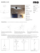
4.2.4.2 Shark with DCI 12-pole
Connections
1) Cable to remote
2) DCI for actuators/lighting (12-pole)
3) Right-hand motor M1
4) Battery 24V
5) Left-hand motor M2
4.2.5 ACT actuator module
A range of adjusting motors, also known as actuators, can be fitted to the mobility device. These
actuators are either connected directly to the electronics module or to a separate actuator module.
The actuator module is connected with the electronics module via a bus cable.
4.2.5.1 ACT 2 actuator module
Connections
1) ACI*
2) Bus cable (to remote or ACT)
3) Bus cable (to remote or ACT)
4) Adjusting motor/actuator - Channel 2
5) Adjusting motor/actuator - Channel 1
* The ACI connection is used for actuator limitation or speed reduction.
4.2.5.2 ACT 4 actuator module
Connections
1) ACI*
2) Bus cable (to remote or electronics
module)
3) Bus cable (to remote or electronics
module)
4) Actuator - Channel 4
5) Actuator - Channel 3
6) Actuator - Channel 2
7) Actuator - Channel 1
* The ACI connection is used for actuator limitation or speed reduction.
4.2.6 Lighting PCB
The lighting PCB connections are printed on the circuit board itself.

5 Maintenance plan (1x annually)
Component Check Remedy Notes
9
• Damage to armrests • Replace covering
if damaged
Armrests
• Armrest fixings • Tighten screws
• Damage to side
panels
• Replace side
panels if damaged
Side panels
• Side panel fixings • Tighten screws
Seat lock
• Seat lock defective • Replace seat lock
Seat angle
adjustment
• Tight seating of SL
fuses
• Replace SL fuses
if necessary
Power backrest
(if fitted)
• Damage to backrest
• Seams
• Fixing
• Check cable
• Check function
• Replace parts if
damaged
• Tighten screws
• Replace cable
motor if necessary
Frames
(chassis) /
battery
mounting
• Check fixings,
welded seams and
battery mounting
• Tighten screws
• Replace
components if
necessary
• Check drive wheels
for tight fit and side
play
• Adjust, replace
wheel hubs
See chapter 7.11.
• Check steering
wheels for tight fit,
float and side play
• Replace wheels,
wheel fork or
wheel bearings
See chapter 7.9.
Wheel
suspension and
wheels
• Pneumatic tyres (if
fitted)
• Repair or replace
if damaged
See chapter 7.10.
Drive units,
coupling
mechanism
• Check functions in
drive and push
modes
• Check coupling
mechanism
• Replace motor if
necessary.
• Tighten
screws/nuts,
adjust or replace if
necessary
Legrests
• Check welded
seams, interlocking,
screws, footplates
• Tighten, replace if
necessary
Power legrests
(if fitted)
• Check cable
• Check contacts
• check functions
• Replace cable if
necessary
Lighting (if
fitted)
• Check cable
• Check function
• Replace lamp or
cable if necessary
• Check batteries for
damage
• Replace batteries
if necessary
See chapter 7.5.
• Check battery
voltage
• Charge batteries
See operating
manual
Batteries
• Check contacts and
terminals
• Clean contacts
and terminals
Please refer to the
safety information
in Chapter 7.5 for
handling batteries

Component Check Remedy Notes
9
Battery case
• Check locking
system, it must
engage completely.
• Replace if
necessary
• Remote, status
display blinking
• Evaluate
error/blink code
• Fixings • Tighten fixings,
replace if
necessary
• Cables and
connecting plugs
• Tighten cables
and connecting
plugs, replace if
necessary
• Drive lever function • Replace drive
lever if necessary
• Replace remote if
necessary
Remote /
electronics
module
• Power supply • Tighten cables
and connecting
plugs, replace if
necessary
Drive program
• Check drive
electronics program
version
• Update software if
newer version
available.
See chapter 7.4.

6 Operational faults
The various electronics modules can be fitted in connection with differing remotes in the mobility
device. Rectification of operational faults is dependent on the electronics module fitted.
The electronics modules used are described in Chapter 4.2.
NOTE:
The tables for rectification of operational faults listed in the following chapters are only an excerpt
from the original manufacturer's manuals.
You can obtain the original manuals from Invacare®.
If you have problems with the mobility device, please proceed as follows:
• First assess the possible cause of the problem using the following table.
• Check the remote status display. Evaluate the error code.
• Carry out the necessary checks and repairs as recommended in the following table.
6.1 Drive fault diagnosis
PROBLEM
OTHER
SYMPTOMS
POSSIBLE
CAUSE
SOLUTION Documentation
Mobility
device will
not start
The remote
status display
illuminates
normally and
does not show
an error code.
Drive motors
disengaged
Engage drive
motors
See operating manual
Remote status
display does
not illuminate
batteries
defective
Replace batteries
See chapter 7.5.
Completely
discharge
battery
Pre-charge
batteries
See operating manual
Power supply
to remote
interrupted
Check master
fuse
See chapter 7.3.
Check cables
between the
modules for
loose
connections and
damage
See chapter 7.7.
Remote
defective
Replace remote
See chapter 7.8.
Remote status
display blinking
Various causes
Assess error
code
See chapter 6.2.

PROBLEM
OTHER
SYMPTOMS
POSSIBLE
CAUSE
SOLUTION Documentation
Batteries
defective
(unstable
voltage)
Replace batteries
See chapter 7.5.
Replace motor(s)
See chapter 7.2.
Mobility
device
judders in
drive mode
None
Drive motor(s)
defective
Replace carbon
brushes
See chapter 7.2.4.
Batteries
not being
charged
None Batteries
defective
Replace batteries
See chapter 7.5.
LEDs blinking
on charging
unit
Charging unit
defective
Replace charging
unit
See charging unit
operating manual
Mobility
device
runs too
slowly
None Remote
defective
Replace remote
See chapter 7.8.
Batteries
defective
Replace batteries
See chapter 7.5.
Electrical
adjustment
motor does
not react
Remote shows
a blinking "E",
status diode on
lighting/actuato
r module does
not go out even
if remote is
switched off or
disconnected.
Lighting /
actuator
module
defective
Replace lighting
/ actuator
module
See chapter 7.3.
None Cable
disconnected
or damaged
Safeguard cable
connection,
replace cable if
necessary
See chapter 7.7.
Electrical
adjusting motor
defective
Check adjusting
motor
See chapter 7.12.
Remote
defective
Replace remote
See chapter 7.8.

6.2 REM24 remote: Error codes and diagnostic codes
The drive electronics can automatically rectify some faults. In this case the status display will stop
blinking. Switch the remote on and off again several times. Wait around 5 seconds each time
before switching the remote on again. If this does not rectify the fault, determine the cause using
the blink codes from the following table.
Blink Code POSSIBLE CAUSE SOLUTION Documentation
1 x blink
Module defective Replace defective
module
See chapter 7.3.
2 x blink
Accessory error (e.g.
short-circuit in adjusting
motor)
Check accessory
connections, check
accessory
See chapter 7.12.
Lifter too high or too low
(seat not at driving
height)
If the lifter is raised, lower
it slowly until the status
display stops blinking. If
the lifter is too low, raise
it slowly until the status
display stops blinking.
Only drive when the seat
is at driving height.
See operating
manual
3 x blink
Error at right-hand motor
Connection
loose/defective or motor
defective
Check connection plug,
check motor
See chapters 7.7
and 7.2
4 x blink
Error at left-hand motor
Connection
loose/defective or motor
defective
Check connection plug,
check motor
See chapters 7.7
and 7.2
5 x blink
Fault/brake fault on right-
hand motor. Connection
loose/defective or motor
defective
Check connection plug See chapters 7.7
and 7.2
6 x blink
Fault/brake fault on left-
hand motor. Connection
loose/defective or motor
defective
Check connection plug See chapters 7.7
and 7.2
7 x blink
Completely discharge
battery
Pre-charge battery See operating
manual
8 x blink
Battery voltage too high Switch lighting to low
battery voltage
Check battery charger
See charging unit
operating manual
9 or 10 x blink
Faulty data transmission
between modules
Remove electronic
modules except for the
power module and the
remote. Replace the
modules one after
another in order to
ensure which was the
one causing the fault.
See chapter 7.3.
11 x blink
Drive motors overloaded /
overheated
Switch remote on and off
/ wait if necessary
-
12 x blink
Compatibility problems
between modules
Remove incorrect module See chapter 7.3.
6.3 VR2 remote: Error codes and diagnostic codes
Evaluate the cause using the following blink codes. The following figure shows which LEDs are
located on the remote.

• The figure shows which LEDs are located on the
remote.
1) Battery display
2) Profile indicator
3) Adjusting motors
Error code POSSIBLE
CAUSE
SOLUTION Documentation
1 LED battery display
Batteries
discharged
Charge battery
Check cable to batteries
See chapter 7.7.
2 LED battery display
Error at left-hand
motor
Connection
loose/defective
or motor
defective
Check connection plug, check
motor
See chapters 7.7
and 7.2
3 LED battery display
Short-circuit in
left-hand motor
Check connection plug, check
motor
See chapters 7.7
and 7.2
4 LED battery display
Error at right-
hand motor
Connection
loose/defective
or motor
defective
Check connection plug, check
motor
See chapters 7.7
and 7.2
5 LED battery display
Short-circuit in
right-hand motor
Check connection plug, check
motor
See chapters 7.7
and 7.2
6 LED battery display
The mobility
device has been
blocked by an
external signal,
for example
because the
charger is
connected.
Remove battery charger
7 LED battery display
Fault on drive
lever
Put the drive lever in a central
position before switching the
remote on.
8 LED battery display
Fault in the
electronics
Check cable See chapter 7.7.
9 LED battery display
The parking
brake is not
working correctly.
Check parking brake
Check cable.
See chapter 7.7.
10 LED battery display
Power surges in
the control box,
e.g. due to bad
connection with
batteries.
Check cable to batteries See chapter 7.7.
7 LED Battery display
plus
5 LED
profile indicator
Compatibility
problems
between
modules
Check cable to remote
Replace remote
See chapter 7.7.

Error code POSSIBLE
CAUSE
SOLUTION Documentation
8 LED Battery display
plus
2 LED
actuators
Actuator error;
if more than one actuator is
fitted, locate the defective
actuator.
Check cable to actuator
See chapter 7.7.
6.4 Shark II remote Error codes and diagnostic codes
The drive electronics can automatically rectify some faults. In this case the status display will stop
blinking. Switch the remote on and off again several times. Wait around 5 seconds each time
before switching the remote on again. If this does not rectify the fault, determine the cause using
the following link codes:
Blink
Code
MEANING SOLUTION Documentation
1
Operating error Set drive lever to neutral central
position (just release drive lever) and
switch on again
Check battery and mains cable See chapter 7.7.
Charge batteries.
If you switch the mobility device off for a
few minutes, the batteries can often
charge themselves up enough to
enable a short journey. You should,
however, only use this solution in
emergency situations because it results
in excessive battery discharging.
See operating manual
2
Battery error
Replace batteries
See chapter 7.5.
3
Fault on left-hand
motor (M2)
Check motor cable and connecting
plug.
Check motor.
See chapters 7.5 and
7.2
4
Fault on right-hand
motor (M1)
Check motor cable and connecting
plug.
Check motor.
See chapters 7.5 and
7.2
5
Fault at left-hand
(M2) motor brake
Check cable and plug. See chapter 7.5.
6
Fault right-hand
(M1) motor brake
Check cable and plug. See chapter 7.5.
7
Error in Shark
remote
Check bus cable in remote and
connecting plug.
Replace remote.
See chapter 7.5.
8
Error in Shark
power module
Check all the cables and plugs in the
Shark system.
Replace electronics module
See chapters 7.5 and
7.3
9
Communication
error in Shark
system
Check all cables and connecting plugs
in the Shark system.
Replace remote.
See chapters 7.5 and
7.3
10
Unknown error Check all cables and connecting plugs. See chapter 7.5.
11
Incompatible
remote
The wrong remote has been connected.
Ensure that electronic module code and
the remote code match.
See chapter 7.3.
/