Page is loading ...

Compass Sport
Service Guide
This Service Guide contains:
Troubleshooting
Replacement Instructions
Illustrated Parts Breakdown

Compass Sport_SG_REVA_041211
1

Compass Sport_SG_REVA_041211
2
Table of Contents
Nomenclature and Contact Information...................................................................................................3
ABOUT THE COMPASS SPORT SERVICE GUIDE............................................................................4
Compass Sport Components...................................................................................................................4-6
The SHARK Battery Gauge......................................................................................................................7
SCENARIO 1: Press the on/off button and the LED array does not light up (SHARK).......................8-9
SCENARIO 2: Batteries will not charge. (Shark Charging Test).........................................................9-10
Electrical System....................................................................................................................................11
Connector Key and Cabling for (SHARK).............................................................................................12
Wiring Diagrams and Battery Placement............................................................................................13-14
TROUBLESHOOTING GUIDE for (SHARK)..................................................................................15-21
Step 1: Checking Battery Voltage..........................................................................................................15
Step 2: Checking “Flash Codes”..........................................................................................................16-20
Flash Code #1 - User Fault.....................................................................................................................17
Flash Code #2 - Battery Fault.................................................................................................................17
Flash Code #3 - Left Motor Fault...........................................................................................................17
Flash Code #4 - Right Motor Fault.........................................................................................................18
Flash Code #5 - Left Park Brake Fault...................................................................................................18
Flash Code #6 - Right Park Brake Fault.................................................................................................19
Flash Code #7 - SHARK Control Unit Fault..........................................................................................19
Flash Code #8 - SHARK Power Module Fault.......................................................................................19
Flash Code #9 - SHARK Communications Fault...................................................................................19
Flash Code #10 - Unknown Fault...........................................................................................................20
Flash Code #11 - Incompatible Control Unit..........................................................................................20
Step 3: Check for other conditions displayed by the Shark Control Unit............................................20-21
All LEDs off...........................................................................................................................................20
All LEDs on steady.................................................................................................................................20
Left red LED flashing.............................................................................................................................20
Right to left LED chase...........................................................................................................................20
Left to right LED chase...........................................................................................................................21
All speedometer LEDs flashing..............................................................................................................21
REPLACEMENT INSTRUCTIONS...................................................................................................22-24
Drive Wheel............................................................................................................................................22
Front Caster.............................................................................................................................................22
Drive Train (Motor/Brake and gearbox).................................................................................................23
Power Module.........................................................................................................................................24
APPENDIX A - HOW TO USE A VOLTMETER..…………………………………………………..25
APPENDIX B - HOW TO USE AN OHM METER..…………………………………………………26
ILLUSTRATED PARTS BREAKDOWN..........................................................................................27-50

Compass Sport_SG_REVA_041211
3
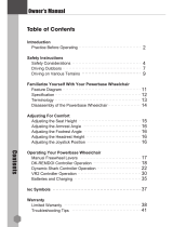
Compass Sport Nomenclature
Contact Information
Golden Technologies
401 Bridge Street
Old Forge, Pa. 18518
Toll-free: 800-624-6374
Fax: 800-628-5165
Lift Chair/Bed Tech: x645
Mobility Tech: x648
VA Tech: x647
Email: parts@goldentech.com
1. Seat Assembly
2. Control Unit (Shark)
3. Right Caster Cover
4. Left Caster Cover
5. Right Fender
6. Left Fender
7. Front Battery Cover
8. Rear Battery Cover
9. Base
10. Right Side Drive Train
11. Front Battery
12. Footplate
13. Power Harness with
Circuit Breaker
14. Left Side Drive Train
15. Power Module (Shark)
16. Bus Cable
17. Rear Battery
18. Control Unit (Joystick)
1
2
3
4
5
6
7
8
9
12
10
11
13
14
15
16
17
18

Compass Sport_SG_REVA_041211
4
About the Compass Sport Service Guide
This service guide provides you with the information necessary to troubleshoot the Golden Technologies
Compass Sport equipped with the Dynamic Shark controller. The troubleshooting scenarios in this manual
consist of procedures that enable you to systematically trace and correct faults in the system.
Before troubleshooting, check the following:
• Make sure that the circuit breaker is reset.
• Visually check terminals for corrosion. Check wires for missing insulation.
• Make sure that the batteries are fully charged and in good working order. When possible, keep sets of
known good batteries of various ratings in your shop at all times. The Compass Sport uses 35AH (U1)
batteries. Problems that surface during troubleshooting are often due to the fact that the batteries are not
fully charged or can not hold their charge.
• Make sure that the electrical connections are secure. Unplug the connectors and make sure all of the
pins are seated properly. Push the pins back into the connector housing if necessary. Make sure that the
battery terminals are tight.
NOTE: If you get to a point during troubleshooting where you cannot continue, call tech support at
800-624-6374.
COMPASS SPORT COMPONENTS
The Compass Sport is a battery-operated power chair controlled by a Dynamic control system. The control
system monitors and displays flash codes on the LED array when it detects a fault in the system. The Compass
Sport was designed to operate with between 18 – 24 volts (V) of direct current (DC).
The Compass Sport control system is made up of the following components. Reference the diagrams on pages
11 and 12.
• 12V/(35AH) Batteries (2)
• Battery Harnesses (2)
• Main Circuit Breaker
• Battery Charger
• Power Harness
• Motors (2) (left/right)
• Park Brakes (2) (left/right)
• SHARK Dynamic Power Module
• SHARK Dynamic Control Unit (Joystick)
• SHARK Bus Cable
NOTE: Parts and service must be authorized by the Golden Technologies Service Department.
Unauthorized parts or service may void the warranty. For more information, contact the Golden
Technologies Service Department at 800-624-6374 or [email protected].
Component: 12VDC (35AH) Batteries (2)
Location: Connected in series inside the battery box.
Function:
Supply 24VDC to the power module. (12VDC x 2).
Connections: Front Battery and Rear Battery.
Failure Signs: Batteries drain quickly. Power chair runs slowly or not at all. Batteries will not charge, but
charger is working properly. Flash Code #2.

Compass Sport_SG_REVA_041211
5
Tests: Load test. Fully charge the batteries first. Make sure charging system is working.
Expected Readings: 12 - 14VDC each when fully charged.
Serviceable: Replace batteries as necessary.
Component: Park Brake (2)
Location: End of each motor.
Function: Park Brake for the motor.
Connections: Each park brake has a 2 pin male connector, which connects to each motor harness.
Failure Signs: Power chair will not move or moves sluggishly. No audible click when the chair stops.
Tests: Test for open. See Flash Codes #5 and #6.
Expected readings: Less than 80 ohms, but not shorted.
Serviceable: Replace if outside this range.
Component: Circuit Breaker
Location: Mounted on the front of the power base.
Function: Protects battery circuit from current overload. When the current draw exceeds the breaker rating, the
circuit breaker will open.
Connections: Terminals on the circuit breaker are connected to the batteries through the power harness.
Failure Signs: Opens repeatedly. This may indicate a failed circuit breaker or short in the wiring. Also, may
open if the motors are overloaded (from excessive weight, short in system, etc.)
Test: Measure the resistance across the circuit breaker. Also check for continuity across the power harness from
the circuit breaker to each battery. Refer to the power harness wiring diagram on page 13.
Expected reading: Less than 10 ohms.
Serviceable: Circuit breaker must be replaced with exact current rating. Replace power harness if no
continuity.
Component: Battery Charger
Location: Stored inside a pouch on the seatback.
Function: Recharges batteries.
Connections: XLR connector connects to the charger port on the front of the control module.
Failure Signs: Charger power LED does not go on. Batteries will not charge.
Tests: Charger tests vary. Some chargers may be tested by measuring positive and negative leads on the charger
connector. Other chargers need to see battery voltage before charging.
Expected reading: Varies with charger.
Serviceable: Replace if necessary.
Component: Motors (2)
Location: Left and right sides of the power base.
Function: Drives the power chair.
Connections: The right motor harness connects to M1 on the power module and the left motor harness connects
to M2 on the power module.
Failure Signs: Power chair runs slowly or not at all.
Tests: Test for internal resistance in motor. Test motor wires for continuity. See Flash Codes #3 and #4.
Expected readings: Internal resistance is less than 5 ohms but not shorted.
Note: Can be as low as 0.3 ohms.
Serviceable: Replace motor if outside range.

Compass Sport_SG_REVA_041211
6
Component: SHARK Power Module
Location: Rear of the power base.
Function: Monitors the system and displays faults when something in the system is out of range. These faults
are displayed as a series of flashes by the battery meter.
Connections: Control unit (joystick), DCI (not used), M1 (right motor), 24V (power harness from batteries),
M2 (left motor). Refer to figures 1 and 2 on pages 11 and 12.
Failure Signs: Flash Code #8.
Tests: Measure voltage at SHARK Bus Connector pin 1 (battery positive) and pin 4 (battery negative).
Expected readings: Battery voltage.
Serviceable: Replace as necessary.
Component: SHARK Control Unit (Joystick)
Location: End of the armrest.
Function: Provides user interface to the power chair. Also, shows battery charge and status of control system.
Connections: XLR charger/programming port on the front of the control module. Bus cable connection on the
back of the control module.
Failure Signs: Flash Code #7
Tests: Measure voltage at pin 1 (battery positive) and pin 2 (battery negative).
Expected readings: Battery voltage.
Serviceable: Replace as necessary.
Component: SHARK Bus Cable
Location: Rear of SHARK Control Unit (Joystick).
Function: Provides connectivity to the SHARK power module.
Connections: 4 pin quick connect bus cable.
Failure Signs: Flash Code #9
Tests: Measure continuity.
Expected readings: Less than 10 ohms.
Serviceable: Replace if open.

Compass Sport_SG_REVA_041211
7
The SHARK Battery Gauge
The following table indicates what the gauge will display for any given state.
The Battery Gauge is used to indicate power on and provides
an estimate of the remaining battery capacity.
Any green LEDs lit indicate well charged batteries.
If only amber and red LEDs are lit, the batteries are
moderately charged.
Recharge before undertaking a long trip.
If only red LEDs are lit, the batteries are running out of
charge. Recharge as soon as possible.

Compass Sport_SG_REVA_041211
8
SCENARIO 1: Press the on/off button and the LED array does not light up.
Before attempting to troubleshoot the power chair, make sure all connectors are connected and seated
properly. Make sure that the batteries are connected properly and fully-charged. Refer to the wiring diagrams
on pages 13 and 14 for the correct wiring. If the batteries are not fully charged or connected properly, then
voltage measurements may produce faulty readings. Measure the voltage across the rear battery negative
(black) terminal and the front battery positive (red) terminal to get battery voltage. If the batteries will not
charge, go to “Scenario 2: Batteries will not charge.”
1. Check the circuit breaker.
• If it is tripped – Reset it.
• Not tripped – Go to the next step.
• Tripped but does not reset – Remove the seat and front battery box cover. Go to step 12.
2. Measure voltage across pin 1 (B+) and pin 2 (B-) on the control unit (Joystick) charging socket.
• 0VDC – Go to the next step.
• 25VDC or (battery voltage) – Replace the control unit.
Prevent damage to the Joystick. Be careful when inserting the meter leads into the charging
socket. Do not allow the meter leads to touch each other, which will cause a short.
3. Disconnect the bus cable from the control unit (Joystick).
4. Measure voltage across pin 1 (+) and pin 4 (-) on the bus cable.
• 0VDC – Go to the next step.
• 25VDC or (battery voltage) – Replace the control unit (Joystick).
5. Remove the seat.
6. Remove the rear battery box cover.
7. Disconnect the bus cable from the power module.
8. Measure voltage across pin 1 (+) and pin 4 (-) on the power module.
• 0VDC – Go to the next step.
• 25VDC or (battery voltage) – Replace bus cable.
Prevent damage to the (Shark) power module. Be careful when touching the leads on the
power module. Do not allow the meter leads to touch each other, which will cause a short.
9. Disconnect the power harness from the power module.
10. Measure voltage across the pin 1 (+) and pin 2 (-) on the power harness.
• 0VDC – Go to the next step.
• 25VDC or (battery voltage) – Replace the power module.
Before attempting to measure resistance, make sure there is no power to the circuit. Unplug
the front and rear battery harnesses from the power harness
11. Measure Resistance across the terminals on the circuit breaker.
• Less than 10 ohms – Go to the next step.
• Open – Replace the circuit breaker.
2 1
4 3
1 2
3 4
1 2

Compass Sport_SG_REVA_041211
9
SCENARIO 1 - Continued
12. Check continuity across the circuit breaker wires of the power harness and across the battery wires of the
power harness. Repair or replace the power harness as necessary.
13. Check continuity across both the front and the rear battery harnesses. If open, check in-line fuse and replace
fuse or harness as necessary. Fuses must be replaced with exact type and rating.
Note: When checking continuity, visually inspect wires, connectors, and pins for any damage and to make sure
the pins are seated properly in their connectors.
SCENARIO 2: Batteries Will Not Charge (Shark Charging Test)
NOTE: Battery chargers will not charge the batteries unless the battery voltage is 18VDC or above and there is
a closed circuit between the batteries. The circuit breaker completes that circuit. Make sure that the circuit
breaker is reset. If necessary, use a set of known good batteries.
1. Check the voltage across pin 1 (+) and pin 2 (-) on the charger XLR connector.
Note: The charger must be plugged in and turned to the on position.
• Greater than 24VDC – Go to the next step.
• Less than 24VDC – Try another wall outlet or known good charger.
Do not touch either of the multimeter probes on the third pin or the XLR connector cover.
You may damage the charger.
2. Remove the seat and the battery box covers.
3. Make sure that the batteries are connected according to the battery connection diagram on the inside of the
battery cover and/or figure 6 on page 14. Check the batteries and cables for corroded or loose terminals. Clean
and tighten if necessary.
4. Measure voltage across the rear battery negative (black) terminal and the front battery positive (red) terminal.
• Less than 18VDC – Load test and replace batteries as necessary.
• Greater than 18VDC – Go to next step.
• 0VDC – Go to step 9.
5. Unplug the battery harnesses from the power harness. Measure the voltage across the battery connectors on
the power harness. Place the red meter lead on the positive pin of the front red connector mounted to the frame.
Place the black meter lead on the negative pin of the rear black connector mounted to the frame. Refer to figure
4 on page 13.
Note: The charger must be plugged in and turned to the on position to perform the testing procedure.
• Greater than 24VDC – Test the battery harnesses for continuity and replace as necessary.
• 0VDC – Go to the next step.
1 2
3
+
_

Compass Sport_SG_REVA_041211
10
SCENARIO 2 - Continued
6. Reconnect the battery harnesses to the power harness. Unplug the power harness from the power module.
Measure voltage across the pin 1 (+) and pin 2 (-) on the power module.
• Greater than 24VDC – Test the power harness for continuity and replace as necessary.
• 0VDC – Go to the next step.
Prevent damage to the (Shark) power module. Be careful when touching the leads on the
power module. Do not allow the meter leads to touch each other, which will cause a short.
7. Reconnect the power harness to the power module. Disconnect the bus cable from the power module.
Measure voltage across pin 1 (+) and pin 4 (-) on the bus cable.
• Greater than 24VDC - Replace the power module.
• 0VDC – Go to the next step.
8. Reconnect the bus cable to the power module. Disconnect the bus cable from the joystick.
Measure voltage across pin 1 (+) and pin 4 (-) on the joystick.
• Greater than 24VDC - Replace the bus cable.
• 0VDC – Replace the control unit.
Before attempting to measure resistance, make sure there is no power to the circuit. Unplug
the front and rear battery harnesses from the power harness.
9. Measure Resistance across the terminals on the circuit breaker.
• Less than 10 ohms – Go to the next step.
• Open – Replace the circuit breaker.
10. Check continuity across the circuit breaker wires of the power harness and across the battery wires of the
power harness. Repair or replace the power harness as necessary.
3 4
1 2
1 2
3 4

Compass Sport_SG_REVA_041211
11
Electrical System
Figure 1. Compass Sport Electrical System Connector Key (Shark)
Not Used
Circuit Breaker
Charging Port
SHARK Bus Cable

Compass Sport_SG_REVA_041211
12
Connector Key for Shark Controller
Note: The Shark controller and the controller harnesses are keyed, eliminating the possibility of the cables from
being incorrectly connected to the controller.
Cabling Diagram
Figure 2. Compass Sport Cabling Diagram (Circuit Breaker not shown)
Left Motor
Right Motor
12 Volt
Battery
Control Unit (Joystick)
SHARK Bus Cable
Motor Harness
Motor Harness
Note: Refer to figure 4 on page 13
for the power harness layout on
the battery side.
Shark Power Module (Controller)
Batter
y
Harness
12 Volt
Battery
Batter
y
Harness

Compass Sport_SG_REVA_041211
13
Wiring Diagrams
Figure 3. Motor/Brake wiring harnesses
Figure 4. Power Harness
+
_
2 pin connector (female)
2 pin connector (female)
Lef
t
Right
orange
orange
red
blue
black
red
blue
black
To D
y
namic Shark Controlle
r
To Brake
To Brake
M2
M1
To D
y
namic Shark Controller Power In
p
u
t
Circuit Breaker
To Batter
y
Harness Connecto
r
To Batter
y
Harness Connecto
r
RED
BLACK

Compass Sport_SG_REVA_041211
14
Wiring Diagrams – continued
Figure 5. Battery Harnesses
Figure 6. Correct Battery Placement
To Power Harness Connectors
To Battery Terminals
To Battery Terminals
BLACK
RED

Compass Sport_SG_REVA_041211
15
Troubleshooting Guide for the Shark Power System
Step 1: Battery voltage is always the first thing to check.
A. Check the battery voltage through the 3-pin battery charger port located on the front of the controller as
shown in figure 1.
Set voltmeter to the 50 VDC scale.
Place the meter leads into the two outside pins of the battery charger port as shown in figure 2.
Meter should read approximately 25 VDC.
B. If the voltage is below 25 VDC:
Recharge the batteries for 8 hours.
Check wiring for any visible damage and make sure all the cables are connected properly.
Make sure that the pins are seated in the connectors properly and the fuses are good.
C. If the voltage is 20 VDC or less:
The battery charger may not recognize a low voltage and thus will not charge the batteries.
Boost charge the batteries to bring the voltage up to a level that the charger will see, then plug the battery
charger into the charger port and charge for 8 hours.
If the batteries will not charge, replace both batteries.
D. If the voltage is dropping too quickly, perform a load test on the batteries using a load tester. If you do not
have access to a load tester, you can load test by performing the follow steps.
Place the meter leads into the outside pins of the battery charger port as shown in figure 2. Sit in the power
chair and drive it.
After an initial drop, the voltage should hold steady at approximately 24VDC or higher when driving with a
load on the chair.
If the voltage continues to drop while driving, replace BOTH batteries.
Figure 1 Figure 2

Compass Sport_SG_REVA_041211
16
Step 2: Check for “FLASH CODES”
Flash Codes
Note: An Amber wrench shaped LED as shown above will display a series of flashes
that give the user visual feedback of the current fault condition.

Compass Sport_SG_REVA_041211
17
Flash Code 1: User Fault
A. Possible stall timeout or user error – Release the joystick to neutral and try again.
Turn the controller off and then on again to clear the fault.
Flash Code 2: Battery Fault
A. Try charging the batteries.
B. Check the battery voltage and cabling. Refer to step 1 on page 15.
C. If the battery voltage fault persists after completing step 1, replace the batteries.
Flash Code 3: Left Motor Fault
A. Check the resistance of the left motor to determine if the fault is in the motor or the controller.
Set your meter to the 20 Ohm scale.
Touch the leads together to make sure the ohm meter is accurate. You should have 0 ohms at this point. If
not, your meter needs to be calibrated.
Place the red and black meter leads on the two outside pins of the connector on the motor as shown in
figure 3.
Meter reading should be between 0.3 and 5 ohms.
Any reading outside this range, replace the motor.
B. Check the resistance of the M2 motor connector on the controller.
Disconnect the battery from the controller.
Set your meter to the 200k ohm scale.
Touch the leads together to make sure the meter is accurate. You should have 0 ohms at this point. If not,
your meter needs to be calibrated.
Place the red and black meter leads on the two outside pins of the M2 motor connector on the controller as
shown in figure 4.
Meter reading should be 22k ohms.
Any reading outside this range, replace the controller.
C. If the reading is within range, and the controller still displays a flash code, check the wiring for visible
damage and that all cables are connected properly. Make sure all connectors are seated properly in their
connectors.
Figure 3 Figure 4

Compass Sport_SG_REVA_041211
18
Flash Code 4: Right Motor Fault
A. Check the resistance of the right motor to determine if the fault is in the motor or the controller.
Set your meter to the 20 Ohm scale.
Touch the leads together to make sure the ohm meter is accurate. You should have 0 ohms at this point. If
not, your meter needs to be calibrated.
Place the red and black meter leads on the two outside pins of the connector on the motor as shown in
figure 5.
Meter reading should be between 0.3 and 5 ohms.
Any reading outside this range, replace the motor.
B. Check the resistance of the M1 motor connector on the controller.
Disconnect the battery from the controller.
Set your meter to the 200k ohm scale.
Touch the leads together to make sure the meter is accurate. You should have 0 ohms at this point. If not,
your meter needs to be calibrated.
Place the red and black meter leads on the two outside pins of the M1 motor connector on the controller as
shown in figure 6.
Meter reading should be 22k ohms.
Any reading outside this range, replace the controller.
C. If the reading is within range, and the controller still displays a flash code, check the wiring for visible
damage and that all cables are connected properly. Make sure all connectors are seated properly in their
connectors.
Figure 5 Figure 6
Flash Code 5: Left Park Brake Fault
A. Make sure the left park brake lever is engaged.
If disengaged, re-engage the park brake lever and turn the power off and back on to reset flash code.
B. Check the resistance of the left park brake, to determine if the fault is in the park brake or in the controller.
Set your meter to the 200 ohm scale.
Touch the leads together to make sure the meter is accurate. You should have 0 ohms at this point. If not,
your meter needs to be calibrated.
Place the red and black meter leads on the two middle pins of the motor connector as shown in figure 7 on
page 19.
Meter reading should be 80 ohms or less, but not shorted.
Any reading outside this range, replace the park brake.
C. If the reading is within range, and the controller still displays a flash code, check the wiring for visible
damage and that all cables are connected properly. Make sure all connectors are seated properly in their
connectors.

Compass Sport_SG_REVA_041211
19
Figure7
Flash Code 6: Right Park Brake Fault
A. Make sure the right park brake lever is engaged.
If disengaged, re-engage the park brake lever and turn the power off and back on to reset flash code.
B. Check the resistance of the right park brake, to determine if the fault is in the park brake or in the controller.
Set your meter to the 200 ohm scale.
Touch the leads together to make sure the meter is accurate. You should have 0 ohms at this point. If not,
your meter needs to be calibrated.
Place the red and black meter leads on the two middle pins of the motor connector as shown in figure 7.
Meter reading should be 80 ohms or less, but not shorted.
Any reading outside this range, replace the park brake.
C. If the reading is within range, and the controller still displays a flash code, check the wiring for visible
damage and that all cables are connected properly. Make sure all connectors are seated properly in their
connectors.
Flash Code 7: SHARK Control Unit Fault
A. Holding the power switch for a timeframe greater then 4 seconds while powering up will cause the remote to
display this flash code. This is not a fault but a safety feature designed to detect if the power button is working
properly. The power button is your emergency stop button for the power chair.
Turn the power off and then on again to reset the fault.
B. Check the SHARK Communications Bus connections and wiring.
C. Check that the wiring is not damaged and that all cables are connected properly.
D. Make sure all pins are seated properly in their connectors.
E. If after performing the previous tests and the fault still persists, or the remote will not turn off, replace the
SHARK control unit.
Flash Code 8: SHARK Power Module Fault
A. Check the SHARK connections and wiring for continuity.
B. Check that the wiring is not damaged.
C. Make sure all pins are seated properly in their connectors.
D. If after performing the previous tests and the fault still persists, replace the SHARK power module.
Flash Code 9: SHARK Communication Fault
A. Check that the battery voltage is greater than 17VDC. Refer to step 1 on page 15.
B. Check the SHARK bus cable for continuity.
C. Make sure all pins are seated properly in their connectors.
D. If after performing the previous tests and the fault still persists, replace both the SHARK control unit and the
SHARK power module.
/