
Edition: 24.07.2013
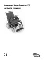
Invacare® Bora/Spectra XTR
SERVICE MANUAL

SERVICE MANUAL
Invacare
®
- Bora/Spectra XTR
2
These instructions contain information about:
Testing work
Repair Instructions
This manual is part of the instructions for use.
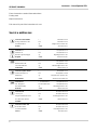
Service addresses
Invacare Austria GmbH
Herzog Odilostrasse 101
A-5310 Mondsee
Austria
(: +43 6232 5 53 50
Fax: +43 6232 5 53 54
@: info@invacare-austria.com
WWW: www.invacare.at
Invacare n.v.
Autobaan 22
B-8210 Loppem (Brugge)
Belgium
(: +32 (0)50 83 10 10
Fax: +32 (0)50 83 10 11
@: belgium@invacare.com
WWW: www.invacare.be
Invacare AG
Benkenstraße 260
CH-4108 Witterswil
Switzerland
(: +41 (0)61487 70 80
Fax: +41 (0)61487 70 81
@: switzerland@invacare.com
WWW: www.invacare.ch
Invacare Aquatec GmbH
Alemannenstraße 10
88316 Isny
Deutschland
( +49 (0)7562 70 00
Fax +49 (0)7562 7 00 66
@: info@invacare-aquatec.com
WWW: www.invacare-aquatec.de
Invacare A/S
Sdr. Ringvej 37
DK-2605 Brøndby
Danmark
( (Kundeservice): +45 (0)36 90 00 00
Fax (Kundeservice): +45 (0)36 90 00 01
@: denmark@invacare.com
WWW: www.invacare.dk
Invacare® SA
c/ Areny s/n
Polígon Industrial de Celrà
E-17460 Celrà (Girona)
ESPAÑA
(: +34 (0)972 49 32 00
Fax: +34 (0)972 49 32 20
@: contactsp@invacare.com
WWW: www.invacare.es
Invacare® Poirier SAS
Route de St Roch
F-37230 Fondettes
France
(: +33 (0)247 62 64 66
Fax: +33 (0)247 42 12 24
@: contactfr@invacare.com
WWW: www.invacare.fr

Invacare
®
- Bora/Spectra XTR
SERVICE MANUAL
3
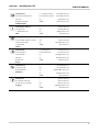
Invacare® Ltd
Pencoed Technology Park
Pencoed
Bridgend CF35 5HZ
United Kingdom
( (Customer services): +44 (0)1656 77 62 22
Fax (Customer services): +44 (0)1656 77 62 20
WWW: www.invacare.co.uk
Invacare Mecc San s.r.l.
Via dei Pini, 62
I - 36016 Thiene (VI)
Italia
(: +39 0445 38 00 59
Fax: +39 0445 38 00 34
@: [email protected]om
WWW: www.invacare.it
Invacare Ireland Ltd.
Unit 5 Seatown Business Campus
Seatown Rd, Swords
County Dublin
Ireland
(: +353 18 10 70 84
Fax: +353 18 10 70 85
@: ireland@invacare.com
WWW: www.invacare.ie
Invacare® AS
Grensesvingen 9
Postboks 6230
Etterstad
N-0603 Oslo
Norge
( (Kundeservice): +47 (0)22 57 95 00
Fax (Kundeservice): +47 (0)22 57 95 01
@: island@invacare.com
WWW: www.invacare.no
Invacare® B.V.
Celsiusstraat 46
NL-6716 BZ Ede
Nederland
(: +31 (0)318 69 57 57
Fax: +31 (0)318 69 57 58
@: nederland@invacare.com
@: csede@invacare.com
WWW: www.invacare.nl
Invacare Lda
Rua Estrada Velha, 949
P-4465-784 Leça do Balio
Portugal
(: +351 225 10 59 46
(: +351 225 10 59 47
Fax: +351 225 10 57 39
@: portugal@invacare.com
WWW: www.invacare.pt

SERVICE MANUAL
Invacare
®
- Bora/Spectra XTR
4
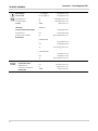
Återförsäljare:
Invacare® AB
Fagerstagatan 9
S-163 91 Spånga
Sverige
Tillverkare:
Invacare® Deutschland GmbH
Kleiststraße 49
D-32457 Porta Westfalica
Deutschland
( (Kundtjänst): +46 (0)8 761 70 90
Fax (Kundtjänst): +46 (0)8 761 81 08
@: [email protected]om
@: finland@invacare.com
WWW: www.invacare.se
MÖLNDAL
(: +46 (0)31 86 36 00
Fax: +46 (0)31 86 36 06
@: ginvacare@invacare.com
LANDSKRONA
(: +46 (0)418 2 85 40
Fax: +46 (0)418 1 80 89
@: linvacare@invacare.com
OSKARSHAMN
(: +46 (0)491 1 01 40
Fax: +46 (0)491 1 01 80
@: oinvacare@invacare.com
Eastern
european
countries
European Distributor
Organisation (EDO)
Kleiststraße 49
D-32457 Porta Westfalica
Deutschland
( +49 (0)5731 75 45 40
Fax +49 (0)5731 75 45 41
@: [email protected]om
WWW: www.invacare.de

Invacare
®
- Bora/Spectra XTR
SERVICE MANUAL
5
Contents
Chapter Page
1 Introduction 9
1.1 General information .................................................................................................................. 9
1.2 Notes on transport .................................................................................................................... 9
1.3 Definition and representation of information and safety information in this manual ...... 10
1.4 Hazard symbols and symbols used ...................................................................................... 11
1.5 Images in this manual ............................................................................................................. 12
2 Safety and fitting instructions 13
2.1 Before any inspection or repair work .................................................................................... 13
2.2 Personal safety equipment ..................................................................................................... 13
2.3 General safety information and information about fitting / removal .................................. 13
3 Tightening torques 16
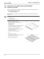
4 Layout of components and componentry 17
4.1 Overview ................................................................................................................................... 17
4.1.1 Wheelchair without lifter ................................................................................................ 17
4.1.2 Wheelchair with lifter ..................................................................................................... 19
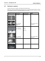
4.2 Electronics modules ............................................................................................................... 21
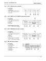
4.2.1 ACS 1 60A electronics module ..................................................................................... 23
4.2.2 ACS 2 PMB70 / ACS 2 PMB70L electronics module ................................................... 23
4.2.3 ACS 2 PMA90LG electronics module ........................................................................... 23
4.2.4 VR2 electronics module ................................................................................................ 23
4.2.5 R-Net electronics module ............................................................................................. 24
4.2.6 Shark electronics module ............................................................................................. 24
4.2.6.1 Shark with 4-pole DCI .............................................................................................. 24
4.2.6.2 Shark with DCI 12-pole ............................................................................................ 24
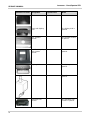
4.2.7 ACT actuator module .................................................................................................... 24
4.2.7.1 ACT 2 actuator module ............................................................................................ 25
4.2.7.2 ACT 4 actuator module ............................................................................................ 25
4.2.8 R-NET ISM lighting and actuator module ..................................................................... 25
4.2.9 Lighting PCB ................................................................................................................. 26
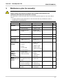
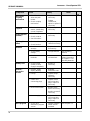
5 Maintenance plan (1x annually) 27

SERVICE MANUAL
Invacare
®
- Bora/Spectra XTR
6
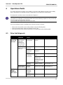
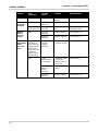
6 Operational faults 29
6.1 Drive fault diagnosis ............................................................................................................... 29
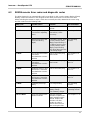
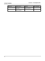
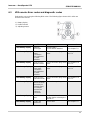
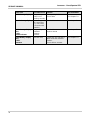
6.2 REM24 remote: Error codes and diagnostic codes ............................................................. 31
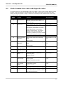
6.3 VR2 remote: Error codes and diagnostic codes .................................................................. 33
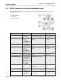
6.4 Shark II remote Error codes and diagnostic codes ............................................................. 35
6.5 R-NET remote: Error codes and diagnostic codes .............................................................. 36
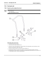
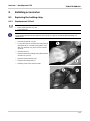
7 Repair work 38
7.1 General warning information about fitting work .................................................................. 38
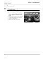
7.2 Replacing drive components ................................................................................................. 38
7.2.1 Replacing the complete drive unit ................................................................................ 40
7.2.2 Replacing the motor ...................................................................................................... 41
7.2.3 Replacing the jaw clutch ............................................................................................... 42
7.2.4 Replace carbon brushes ............................................................................................... 43
7.2.5 Replacing the motor / gearbox unit (SSD motor).......................................................... 44
7.2.6 Replacing or rotating the motor / gearbox unit sealing ring .......................................... 46
7.2.7 Replacing the motor / gearbox coupling (SSD motor) .................................................. 47
7.2.8 Replacing the carbon brushes (SSD motor) ................................................................. 49
7.2.9 Replacing the drive wheel hub (SSD motor) ................................................................ 51
7.3 Replacing the electronics ....................................................................................................... 53
7.4 Replacing the G-Trac sensor.................................................................................................. 55
7.5 Operating hours counter ........................................................................................................ 57
7.5.1 Replacing the operating hours counter ......................................................................... 57
7.5.2 Replacing the connecting cable of the operating hours counter .................................. 59
7.6 Updating software ................................................................................................................... 61
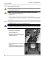
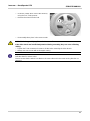
7.7 Replacing batteries ................................................................................................................. 62
7.7.1 Removing the battery cases ......................................................................................... 63
7.7.2 Removing the batteries ................................................................................................. 65
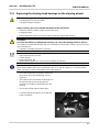
7.7.3 Correct handling of damaged batteries ........................................................................ 69
7.8 Checking and replacing the main fuse .................................................................................. 70
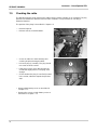
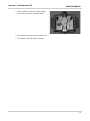
7.9 Checking the cable .................................................................................................................. 72
7.10 Differences when replacing the REM24 remote ................................................................... 74
7.11 Lighting unit ............................................................................................................................. 75
7.11.1 Replacing front headlight completely (LED lighting unit) .............................................. 75
7.11.2 Replacing the front bulb holder (LED lighting unit) ....................................................... 76
7.11.3 Replacing the rear light completely (LED lighting unit) ................................................. 77
7.12 Anti-tipping mechanism .......................................................................................................... 78
7.12.1 Replacing the anti-tipping mechanism with screw ........................................................ 78
7.12.2 Replacing the anti-tipping mechanism with locking spring ........................................... 79

Invacare
®
- Bora/Spectra XTR
SERVICE MANUAL
7
7.12.3 Replacing a defective locking spring ............................................................................ 80
7.13 Replacing the steering head bearings on the steering wheels .......................................... 81
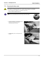
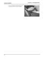
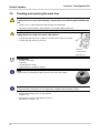
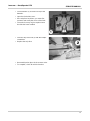
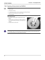
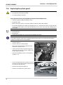
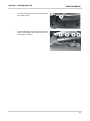
7.14 Repairing punctures ................................................................................................................ 84
7.14.1 Repairing the rear tyre (wheel size 3.00-8") ................................................................. 84
7.14.2 Repairing a flat tyre (wheel size 280/250-4) ................................................................. 86
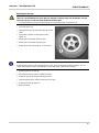
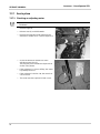
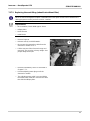
7.15 Replacing a drive wheel .......................................................................................................... 88
7.16 Replacing the splash guard .................................................................................................... 90
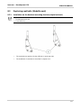
7.17 Seat system .............................................................................................................................. 92
7.17.1 Checking an adjusting motor ........................................................................................ 92
7.17.2 Replacing the seat tilting (wheelchair without lifter) ..................................................... 93
7.17.3 Replacing the lifter ........................................................................................................ 95
7.18 Backrest unit ............................................................................................................................ 97
7.18.1 Replacing the standard backrest .................................................................................. 97
7.18.2 Adjusting backrest former ............................................................................................. 98
7.19 Seat system Modulite .............................................................................................................. 99
7.19.1 Replacing the tilt actuator ............................................................................................. 99
7.19.2 Replacing the lifter actuator ........................................................................................ 100
7.19.3 Replacing the lifter / seat angle adjustment module ................................................... 101
7.19.4 Replacing the angle sensor ........................................................................................ 104
7.19.5 Replacing the backrest actuator ................................................................................. 105
7.19.6 Backrest actuator - Removing the adapter ................................................................. 106
7.20 Backrest Modulite .................................................................................................................. 107
7.20.1 Replacing the standard backrest ................................................................................ 107
7.20.2 Replacing the backrest mounting bracket .................................................................. 108
7.20.3 Replacing the backrest mounting bracket for SB 53 .................................................. 109
7.21 Adjusting the seat width/ backrest width (Modulite) ......................................................... 110
7.21.1 Adjusting the seat width .............................................................................................. 110
7.21.2 Adjusting the backrest width ....................................................................................... 112
7.21.3 Adjusting the Flex3 backrest....................................................................................... 114
8 Installing accessories 115
8.1 Replacing the holding strap ................................................................................................. 115
8.1.1 Standard seat & Flex2 ................................................................................................ 115
8.1.2 Fixed seat unit ............................................................................................................ 116
8.2 Replacing seat belts (Modulite seat) ................................................................................... 117
8.2.1 Installation on the backrest mounting bracket (simple backrest) ................................ 117
8.2.2 Installation on the backrest mounting bracket (adjustable seat) ................................ 118
8.2.3 Installation on the seat frame profile (adjustable seat) ............................................... 119
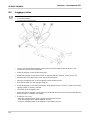
8.3 Luggage carrier ..................................................................................................................... 120
8.4 Further accessories .............................................................................................................. 121

SERVICE MANUAL
Invacare
®
- Bora/Spectra XTR
8
9 Adjusting the seating position 122
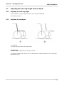
9.1 Adjusting the lower leg length and seat depth................................................................... 123
9.1.1 Adjusting the lower leg length ..................................................................................... 123
9.1.2 Adjusting the seat depth ............................................................................................. 123
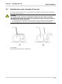
9.2 Adjusting the center of gravity of the seat ......................................................................... 125
9.2.1 Standard seat ............................................................................................................. 127
9.2.2 Flex2 seat ................................................................................................................... 129
9.2.3 Modulite seat .............................................................................................................. 130
9.2.3.1 Adjustable seats .................................................................................................... 132
9.2.3.2 Simple seat ............................................................................................................ 133
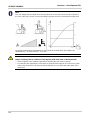
9.3 Check the tipping stability .................................................................................................... 134

Invacare
®
- Bora/Spectra XTR
SERVICE MANUAL
9
1 Introduction
1.1 General information
• Service and maintenance work must be carried out taking this service manual into account.
• It is imperative that you observe safety information.
• Information about operation or about general maintenance and care work on the mobility device
should be taken from the operating manual.
• You can find information about ordering spare parts in the spare parts catalogue.
• Only use original Invacare® spare parts. The guarantee will become invalid if other spare parts
are used!
• We reserve the right to make any alterations on the grounds of technical improvements.
• The mobility device may only be maintained and overhauled by qualified personnel.
• The minimum requirement for service technicians is suitable training, such as in the cycle or
orthopaedic mechanics fields, or sufficiently long-term job experience.
- Experience in the use of electrical measuring equipment (multimeters) is also a requirement.
- Special Invacare training is recommended.
• Alterations to the mobility device which occur as a result of incorrectly or improperly executed
maintenance or overhaul work lead to the exclusion of all liability on the side of INVACARE.
• If you have any problems or questions please contact Invacare Service.
1.2 Notes on transport
• If the mobility device has to be shipped back to the manufacturer for major repairs, you should
always use the original packaging for transport.
• You must include a precise fault description.

SERVICE MANUAL
Invacare
®
- Bora/Spectra XTR
10
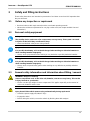
1.3 Definition and representation of information and safety
information in this manual
Different types of information and signal words are used throughout this manual.
HAZARD!
The signal word "HAZARD!" refers to immediate hazards.
• The following lines in italics refer to actions which serve to avoid such hazards.
WARNING!
The signal word "WARNING!" refers to possibly-occurring hazards which can lead to
death or serious injuries if they are not avoided.
• The following lines in italics refer to actions which serve to avoid such hazards.
ATTENTION!
The signal word "ATTENTION!" refers to possibly-occurring hazards which can lead to
minor injuries and/or material damage if they are not avoided.
• The following lines in italics refer to actions which serve to avoid such hazards.
CAUTION!
The signal word "CAUTION!" refers to hazards which could lead to material damage if
they are not avoided.
• The following lines in italics refer to actions which serve to avoid such hazards.
Note
The signal word "Note" is used to denote general information which simplifies the handling of
your product and refers to special functions.

Invacare
®
- Bora/Spectra XTR
SERVICE MANUAL
11
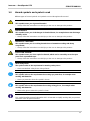
1.4 Hazard symbols and symbols used
Different types of hazard symbols and symbols are used throughout this manual.
General hazards
This symbol warns you of general hazards!
• Always follow the instructions to avoid injury to the user or damage to the product!
BURN HAZARD!
This symbol warns you of the danger of chemical burns, for example due to the discharge
of battery acids!
• Always follow the instructions to avoid injury to the user or damage to the product!
DANGER OF CRUSHING!
This symbol warns you of crushing hazards due to inattentive working with heavy
components.
• Always follow the instructions to avoid injury to the user or damage to the product!
EXPLOSION HAZARD!
This symbol warns you of an explosion hazard, which can be caused by excessive tyre
pressure in a pneumatic tyre.
• Always follow the instructions to avoid injury to the user or damage to the product!
Wear safety shoes
The symbol refers to the requirement for wearing safety shoes.
• Wear standardised safety shoes during all work.
Wear eye protection
This symbol refers to the requirement for wearing eye protection, for example when
working with batteries.
• Wear eye protection when this symbol is shown.
Wear safety gloves
This symbol refers to the requirement for wearing safety gloves, for example when
working with batteries.
• Wear safety gloves when this symbol is shown.
Note
This symbol identifies general information which is intended to simplify working with your product
and which refers to special functions.

SERVICE MANUAL
Invacare
®
- Bora/Spectra XTR
12
Requirements:
• This symbol identifies a list of various tools, components and items which you will need in
order to carry out certain work. Please do not attempt to carry out the work if you do not have
the listed tools available.
Always dispose used or damaged batteries correctly
The symbol refers to information for the correct disposal of used or damaged batteries.
1.5 Images in this manual
The detailed images in this manual are given digits to identify various components. Component
numbers in text and operational instructions always relate to the image directly above.

Invacare
®
- Bora/Spectra XTR
SERVICE MANUAL
13
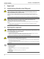
2 Safety and fitting instructions
These safety instructions are intended as prevention of accidents at work and it is imperative that
they are observed.
2.1 Before any inspection or repair work
• Read and observe this repair manual and the associated operating manual!
• Observe the minimum requirements for carrying out the work (see chapter entitled "General
information”).
2.2 Personal safety equipment
Safety shoes
The mobility device, and some of its components, are very heavy. These parts can result
in injuries to the feet if they are allowed to drop.
• Wear standardised safety shoes during all work.
Eye protection
It is possible that battery acid can be discharged when working on defective batteries or
when handling batteries improperly.
• Always wear eye protection when working on any defective or possibly defective batteries.
Safety gloves
It is possible that battery acid can be discharged when working on defective batteries or
when handling batteries improperly.
• Always wear acid-proof safety gloves when working on any defective or possibly defective
batteries.
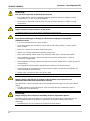
2.3 General safety information and information about fitting / removal
WARNING: Danger of crushing!
Various components such as the drive unit, batteries, seat etc are very heavy. This results
in injury hazards to your hands!
• Please note the high weight of some components! This applies especially to the removal of
drive units, batteries and the seat.
WARNING!
Injury hazard if the vehicle starts moving unintentionally during repair work!
• Switch the power supply off (ON/OFF key)!
• Engage the drive!
• Before raising the vehicle, secure the wheels by blocking them with wedges!

SERVICE MANUAL
Invacare
®
- Bora/Spectra XTR
14
ATTENTION!
Fire and burn hazard due to electrical short-circuit!
• The mobility device must be completely switched off before removal of voltage-carrying
components! To do this, remove the batteries.
• Avoid short-circuiting the contacts when carrying out measurements on voltage-carrying
components!
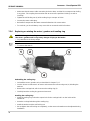
CAUTION!
Danger of burns from hot surfaces on the motor!
• Allow the motors to cool down before commencing work on them.
ATTENTION!
Injury hazard and danger of damage to vehicle due to improper or incomplete
maintenance work!
• Use only undamaged tools in good condition.
• Some moving parts are mounted in sockets with PTFE coating (Teflon™). Never grease
these sockets!
• Never use "normal" nuts instead of self-locking nuts.
• Always use correctly-dimensioned washers and spacers
• When reassembling, always replace any cable ties which were cut during dismantling.
• After completing your work / before renewed start-up of the mobility device, check all
connections for tight fitting.
• After completing your work / before renewed start-up of the mobility device, check all parts for
correct locking.
• Only operate the vehicle with the approved tyre pressures (see technical data).
• Check all electrical components for correct function. Please note that incorrect polarity can
result in damage to the electronics.
• Always carry out a trial run at the end of your work.
CAUTION!
Danger of injury and damage to property, if the maximum speed reduction on a
wheelchair with a lifter does not function correctly!
The wheelchair’s control unit must reduce the maximum possible speed as soon as the lifter is
raised.
• Test the maximum speed reduction for correct function after any maintenance work or
modifications to the wheelchair.
ATTENTION!
Danger of injury due to improper retrofitting of electric adjustment options.
Retrofitting electric adjustment options is a fundamental change to the configuration and can
have a negative impact on the driving characteristics and tipping stability of the electric
wheelchair.
• Retrofitting may only be performed by trained Invacare® dealers.

Invacare
®
- Bora/Spectra XTR
SERVICE MANUAL
15
Note
Mark all current settings for the mobility device (seat, armrests, backrest etc.), and the
associated cable connecting plugs, before dismantling. This makes reassembly easier.
All plugs are fitted with mechanical safety devices which prevent release of the connecting plugs
during operation. To release the connecting plugs the safety devices must be pressed in. When
reassembling ensure that these safety devices are correctly engaged.
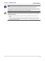
WARNING!
Any changes to the drive program can affect the driving characteristics and the tipping
stability of the vehicle!
• Changes to the drive program may only be carried out by trained Invacare® specialist
dealers!
• Invacare® supplies all mobility devices with a standard drive program ex-works. Invacare®
can only give a warranty for safe vehicle driving behaviour - especially the tipping stability -
for this standard drive program!

SERVICE MANUAL
Invacare
®
- Bora/Spectra XTR
16
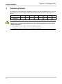
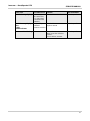
3 Tightening torques
The tightening torques stated in the following list are based on the thread diameter for the nuts and
bolts for which no specific values have been determined.All values assume dry and de-greased
threads.
Thread
M4 M5 M6 M8 M10 M12 M14 M16
Tightening torque
in Nm ±10%
3 Nm 6 Nm 10 Nm 25 Nm 49 Nm 80 Nm 120 Nm 180 Nm
CAUTION!
Damage can be caused to the mobility device due to improperly tightened screws, nuts or
plastic connections.
• Always tighten screws, nuts etc to the stated tightening torque.
• Only tighten screws or nuts which are not listed here fingertight.


SERVICE MANUAL
Invacare
®
- Bora/Spectra XTR
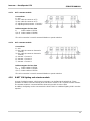
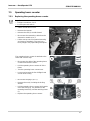
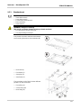
18
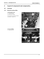
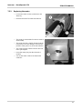
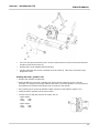
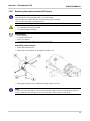
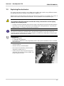
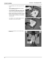
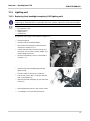
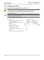
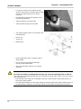
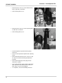
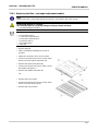
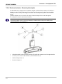
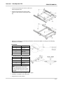
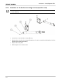
Actuator module
4) Actuator module
The actuator module is fitted under the
seat support.
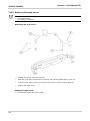
G-Trac sensor
5) G-Trac sensor
The optional G-Trac sensor is located in
the front, next to the battery connector.
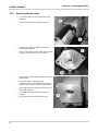
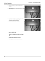
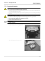
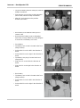
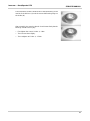
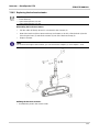
Operation hour counter
6) Operation hour counter
The optional operation hour counter is
mounted laterally on the frame.

Invacare
®
- Bora/Spectra XTR
SERVICE MANUAL
19
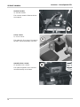
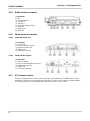
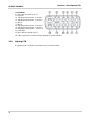
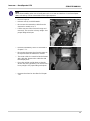
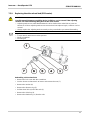
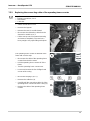
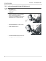
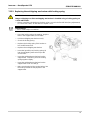
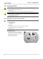
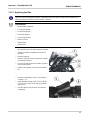
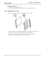
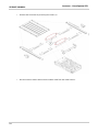
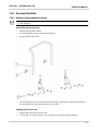
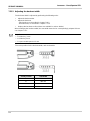
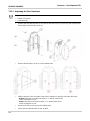
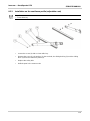
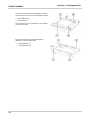
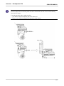
4.1.2 Wheelchair with lifter
In front of the batteries under the
plastic cover:
1) Electronics module
2) Lighting PCB (optional)
3) Plastic cover
The electronics modules used are
described in Chapter 4.2.
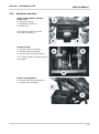
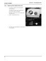
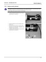
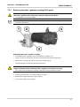
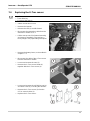
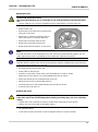
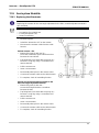
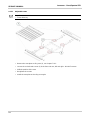
Actuator module
4) Actuator module 1 (optional)
5) Actuator module 2 (optional)
6) Actuator motor backrest (optional)
The actuator modules are fitted under the
seat support.
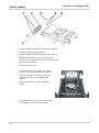
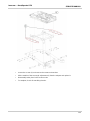
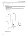
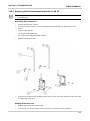
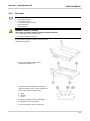
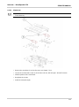
Electric seat adjustment
6) Actuator motor backrest (optional)
7) Actuator motor seat tilting

SERVICE MANUAL
Invacare
®
- Bora/Spectra XTR
20
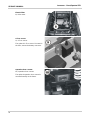
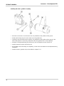
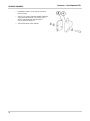
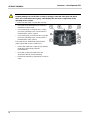
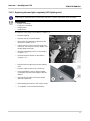
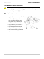
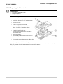
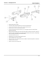
Electric lifter
8) Lifter motor
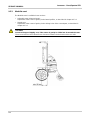
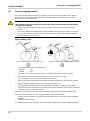
G-Trac sensor
9) G-Trac sensor
The optional G-Trac sensor is located in
the front, next to the battery connector.
Operation hour counter
10) Operation hour counter
The optional operation hour counter is
mounted laterally on the frame.
Page is loading ...
Page is loading ...
Page is loading ...
Page is loading ...
Page is loading ...
Page is loading ...
Page is loading ...
Page is loading ...
Page is loading ...
Page is loading ...
Page is loading ...
Page is loading ...
Page is loading ...
Page is loading ...
Page is loading ...
Page is loading ...
Page is loading ...
Page is loading ...
Page is loading ...
Page is loading ...
Page is loading ...
Page is loading ...
Page is loading ...
Page is loading ...
Page is loading ...
Page is loading ...
Page is loading ...
Page is loading ...
Page is loading ...
Page is loading ...
Page is loading ...
Page is loading ...
Page is loading ...
Page is loading ...
Page is loading ...
Page is loading ...
Page is loading ...
Page is loading ...
Page is loading ...
Page is loading ...
Page is loading ...
Page is loading ...
Page is loading ...
Page is loading ...
Page is loading ...
Page is loading ...
Page is loading ...
Page is loading ...
Page is loading ...
Page is loading ...
Page is loading ...
Page is loading ...
Page is loading ...
Page is loading ...
Page is loading ...
Page is loading ...
Page is loading ...
Page is loading ...
Page is loading ...
Page is loading ...
Page is loading ...
Page is loading ...
Page is loading ...
Page is loading ...
Page is loading ...
Page is loading ...
Page is loading ...
Page is loading ...
Page is loading ...
Page is loading ...
Page is loading ...
Page is loading ...
Page is loading ...
Page is loading ...
Page is loading ...
Page is loading ...
Page is loading ...
Page is loading ...
Page is loading ...
Page is loading ...
Page is loading ...
Page is loading ...
Page is loading ...
Page is loading ...
Page is loading ...
Page is loading ...
Page is loading ...
Page is loading ...
Page is loading ...
Page is loading ...
Page is loading ...
Page is loading ...
Page is loading ...
Page is loading ...
Page is loading ...
Page is loading ...
Page is loading ...
Page is loading ...
Page is loading ...
Page is loading ...
Page is loading ...
Page is loading ...
Page is loading ...
Page is loading ...
Page is loading ...
Page is loading ...
Page is loading ...
Page is loading ...
Page is loading ...
Page is loading ...
Page is loading ...
Page is loading ...
Page is loading ...
Page is loading ...
-
 1
1
-
 2
2
-
 3
3
-
 4
4
-
 5
5
-
 6
6
-
 7
7
-
 8
8
-
 9
9
-
 10
10
-
 11
11
-
 12
12
-
 13
13
-
 14
14
-
 15
15
-
 16
16
-
 17
17
-
 18
18
-
 19
19
-
 20
20
-
 21
21
-
 22
22
-
 23
23
-
 24
24
-
 25
25
-
 26
26
-
 27
27
-
 28
28
-
 29
29
-
 30
30
-
 31
31
-
 32
32
-
 33
33
-
 34
34
-
 35
35
-
 36
36
-
 37
37
-
 38
38
-
 39
39
-
 40
40
-
 41
41
-
 42
42
-
 43
43
-
 44
44
-
 45
45
-
 46
46
-
 47
47
-
 48
48
-
 49
49
-
 50
50
-
 51
51
-
 52
52
-
 53
53
-
 54
54
-
 55
55
-
 56
56
-
 57
57
-
 58
58
-
 59
59
-
 60
60
-
 61
61
-
 62
62
-
 63
63
-
 64
64
-
 65
65
-
 66
66
-
 67
67
-
 68
68
-
 69
69
-
 70
70
-
 71
71
-
 72
72
-
 73
73
-
 74
74
-
 75
75
-
 76
76
-
 77
77
-
 78
78
-
 79
79
-
 80
80
-
 81
81
-
 82
82
-
 83
83
-
 84
84
-
 85
85
-
 86
86
-
 87
87
-
 88
88
-
 89
89
-
 90
90
-
 91
91
-
 92
92
-
 93
93
-
 94
94
-
 95
95
-
 96
96
-
 97
97
-
 98
98
-
 99
99
-
 100
100
-
 101
101
-
 102
102
-
 103
103
-
 104
104
-
 105
105
-
 106
106
-
 107
107
-
 108
108
-
 109
109
-
 110
110
-
 111
111
-
 112
112
-
 113
113
-
 114
114
-
 115
115
-
 116
116
-
 117
117
-
 118
118
-
 119
119
-
 120
120
-
 121
121
-
 122
122
-
 123
123
-
 124
124
-
 125
125
-
 126
126
-
 127
127
-
 128
128
-
 129
129
-
 130
130
-
 131
131
-
 132
132
-
 133
133
-
 134
134


Invacare Bora User manual
- Type
- User manual
- This manual is also suitable for
Ask a question and I''ll find the answer in the document
Finding information in a document is now easier with AI
Related papers
-
Invacare Spectra XTR User manual
-
Invacare Kite User manual
-
Invacare Fox User manual
-
Invacare FDX User manual
-
Invacare Dragon User manual
-
-
-
-
-
Other documents
-
CAL Lighting BO-2780TR-BS Operating instructions
-
Spalding M4115231 User manual
-
Benjara BM273196 Operating instructions
-
Homestyles 5552-305 Operating instructions
-
Cake Makka Front Carrier Operating instructions
-
 Furniture of America IDF-3185DG-SC Installation guide
-
Human Touch HT-5040 User manual
-
Liberty Garden SS-K-030EB-3 Installation guide
-
-
