Go Power GP-3000HD User manual
- Category
- Power adapters & inverters
- Type
- User manual
This manual is also suitable for

MODIFIED SINE WAVE
INVERTER
GP-1750/3000/5000HD
User Manual
© 2017 Go Power!
®
Worldwide Technical Support and Product Information gpelectric.com
Go Power! Corporate Headquarters
250 Bay St, Victoria, BC Canada V9A 3K5
Tel: 1.866.247.6527
80691_MANUAL_GP-1750-3000-5000-HD_RevA

[page 2] | gpelectric.com
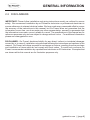
1. CONTENTS
1. CONTENTS ........................................................................... 2
2. GENERAL INFORMATION .................................................... 3
2.1 CAUTIONS / WARNINGS ..................................................................... 3
2.2 DISCLAIMERS ..................................................................................... 9
2.3 MODIFIED HD FEATURES ................................................................ 10
3. SPECIFICATIONS ............................................................... 12
4. INSTALLATION ................................................................... 15
4.1 INSTALLATION PRECAUTIONS ........................................................ 15
4.2 INVERTER SHUTDOWN .................................................................... 16
4.3 WHERE TO INSTALL ......................................................................... 16
4.5 INSTALLATION AND TESTING .......................................................... 17
4.6 BATTERY PRECAUTIONS ................................................................. 19
4.7 DC WIRING SIZING ........................................................................... 20
4.8 DC GROUNDING ............................................................................... 21
5. OPERATION ........................................................................ 22
5.1 OPERATING PRECAUTIONS ............................................................ 22
5.2 CONNECTING AC LOADS ................................................................. 23
5.3 CONTROLS AND INDICATORS ......................................................... 23
5.4 OPTIONAL ON/OFF REMOTE ........................................................... 23
5.5 POWER OUTPUT............................................................................... 24
5.6 INPUT VOLTAGE ................................................................................ 25
5.7 OVERTEMP ........................................................................................ 25
5.8 OVERLOAD ........................................................................................ 25
6. TROUBLESHOOTING ........................................................ 26
6.1 TROUBLESHOOTING GUIDE ........................................................... 26
7. MAINTENANCE .................................................................. 27
7.1 SERVICING PRECAUTIONS ............................................................. 27
7.2 MAINTENANCE .................................................................................. 27
8. WARRANTY RETURN PROCEDURE ................................ 28
9. END OF LIFE - RECYCLING .............................................. 29

gpelectric.com | [page 3]
2. 1 CAUTIONS / WARNINGS
This document contains important safety instructions for the products produced by
Go Power! Read all instructions and cautionary markings on the product and on any
accessories or additional equipment included in the installation. Failure to follow these
instructions could result in severe shock or possible electrocution. Use extreme caution at all
times to prevent accidents.
All electrical work must be performed in accordance with local and national electrical codes.
These instructions are for use by qualied personnel who meet all local and governmental
code requirements for licensing and training for the installation of electrical power systems
with AC and DC voltage up to 600 volts.
Installation, maintenance, and connection of inverters must be performed by qualied
personnel, in compliance with local electrical standards, wiring rules, and the requirements
of local power authorities and/or companies.
Safety regulations relevant to the location shall be followed during installation, operation and
maintenance. Improper operation may have a risk of electric shock or damage to equipment
and property.
2. GENERAL INFORMATION

[page 4] | gpelectric.com
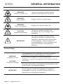
GENERAL INFORMATION
General Safety
WARNING!
Limitations on Use
CAUTION!
Equipment Damage
This equipment is NOT intended for use with life support
equipment or other medical equipment or devices.
This product is designed for indoor/compartment
installation. It must not be exposed to any liquids, moisture
of any type.
Only use components or accessories recommended or sold
by Go Power! or its authorized agents.
IMPORTANT
Do not attempt to install this equipment if it appears to
be damaged in any way. See the Warranty section for
instructions on returning the equipment.
WARNING!
Hazard to Human Life
This type of notation indicates that the
hazard could be harmful to human life.
WARNING!
Shock Hazard
Danger of shock or electrocution.
WARNING!
Burn / Fire Hazard
Danger of hot surface and/or re.
CAUTION!
Hazard to Equipment
This type of notation indicates that
the hazard may cause damage to the
equipment.
IMPORTANT
This type of notation indicates that the
information provided is important to the
installation, operation and/or maintenance
of the equipment. Failure to follow the
recommendations in such a notation could
result in annulment of the equipment
warranty.
i

gpelectric.com | [page 5]
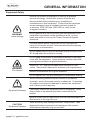
GENERAL INFORMATION
Personal Safety
WARNING!
Personal Injury
Use safe lifting techniques when lifting this equipment as
recommended by the Occupational Safety and Health
Association (OSHA) or other local codes.
Use standard safety equipment when working on this
equipment, such as safety glasses, ear protection, steel-
toed safety boots, safety hard hats, etc.
Use standard safety practices when working with electrical
equipment. (Remove all jewelry, use insulated tools, wear
cotton clothing, etc.)
Never work alone when installing or servicing this
equipment. Have someone nearby that can assist if
necessary.
Ensure that children, pets, and other animals are kept away
from the inverter, solar arrays, battery bank, and utility grid
components.
If the equipment is used in a manner not specied by the
manufacturer, the protection provided by the equipment may
be impaired.
People with pacemakers should consult their physician(s)
before use. Electromagnetic elds in close proximity to
heart pacemakers could cause pacemaker interference or
pacemaker failure.
The brass components of this product contain lead, a
chemical known to the State of California to cause birth
defects or other reproductive harm.
This product contains or, when used, produces a chemical
known to the State of California to cause cancer and birth
defects or other reproductive harm.
The warnings, precautions, and instructions in this manual
cannot cover all possible conditions and situations that may
occur. It must be understood by the operator that common
sense and caution are factors which cannot be built into this
product, but must be supplied by the operator.

[page 6] | gpelectric.com
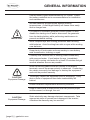
Equipment Safety
WARNING!
Lethal Voltage
Review the system conguration to identify all possible
sources of energy. Ensure ALL sources of power are
disconnected before performing any installation or
maintenance on this equipment. Conrm that the terminals
are de-energized using a validated voltmeter (rated for
a minimum 1000 VAC and 1000 VDC) to verify the de-
energized condition.
Do not perform any servicing other than that specied in the
installation instructions unless qualied to do so, or have
been instructed to do so by Go Power! Technical Support
personnel.
To avoid electric shock, disconnect the DC input and AC
input of the inverter at least 5 minutes before performing any
installation or maintenance.
Do not tighten the AC and DC terminals or pull on the AC and
DC wiring when the inverter is running.
WARNING!
Fire Hazard
Do not keep combustible or ammable materials in the same
room with the equipment. Some products contain relays with
moving parts and are not ignition-protected.
Ensure AC, DC, and ground cable sizes conform to local
codes. See product manuals for minimum size requirements.
Ensure all conductors are in good condition.
Do not operate the unit with damaged or substandard cabling.
CAUTION!
Equipment Damage
When connecting cables from the inverter to the battery
terminals, ensure the proper polarity is observed. Connecting
the cables incorrectly can damage or destroy the equipment
and void the product warranty.
Thoroughly inspect the equipment prior to energizing. Verify
that no tools or equipment have been inadvertently left
behind.
Keep all vents clear of obstructions that can prevent proper air
ow around, or through, the unit.
CAUTION!
Equipment Damage
Static electricity may damage electronic components. Take
appropriate steps to prevent such damage to the inverter;
otherwise the warranty may be annulled.
GENERAL INFORMATION

gpelectric.com | [page 7]
Battery Safety
WARNING!
Explosion, Electrocution,
or Fire Hazard
Ensure the cables (conductors) are properly sized.
Ensure clearance requirements are strictly enforced around
the batteries.
Ensure the area around the batteries is well ventilated and
clean of debris.
Never smoke, or allow a spark or ame near, the batteries.
Always use insulated tools. Avoid dropping tools onto
batteries or other electrical parts.
Never charge a frozen battery.
Never use old or untested batteries. Check each battery’s
label for age, type, and date code to ensure all batteries are
identical.
If a battery must be removed, always remove the grounded
terminal from the battery rst. Make sure all devices are de-
energized or disconnected to avoid causing a spark.
GENERAL INFORMATION

[page 8] | gpelectric.com
IMPORTANT
Use the battery types recommended by Go Power! Follow
the battery manufacturer’s recommendations for installation
and maintenance.
Insulate batteries as appropriate against freezing
temperatures. A discharged battery will freeze more easily
than a charged one.
If a remote or automatic generator control system is used,
disable the starting circuit and/or disconnect the generator
from its starting battery while performing maintenance to
prevent accidental starting.
Wear complete eye and clothing protection when working
with batteries. Avoid touching bare skin or eyes while working
near batteries.
Keep plenty of fresh water and soap nearby in case battery
acid contacts skin, clothing, or eyes.
If battery acid contacts skin or clothing, wash immediately
with soap and water. If acid enters the eye, immediately
ood it with running cold water for at least 20 minutes and get
medical attention as soon as possible.
CAUTION!
Equipment Damage
When connecting cables from the inverter to the battery
terminals, ensure the proper polarity is observed. Connecting
the cables incorrectly can damage or destroy the equipment
and void the product warranty.
Thoroughly inspect the equipment prior to energizing. Verify
that no tools or equipment have been inadvertently left
behind.
Ensure clearance requirements are strictly enforced.
Keep all vents clear of obstructions that can prevent proper
air ow around, or through, the unit.
CAUTION!
Equipment Damage
Static electricity may damage electronic components. Take
appropriate steps to prevent such damage to the inverter;
otherwise the warranty may be annulled.
i
GENERAL INFORMATION

gpelectric.com | [page 9]
2.2 DISCLAIMERS
IMPORTANT: Please follow installation and wiring instructions exactly as outlined to ensure
safety. We recommend installation by an RV/marine technician or professional electrician to
ensure adherence to relevant electrical codes. We have made every reasonable effort to ensure
the accuracy of the instructions in this manual, but Go Power! does not guarantee that the
information is error free, nor do we make any other representation, warranty or guarantee that
the information is accurate, correct, reliable or current. The specications in this manual are for
reference purposes only and are subject to change without notice. For additional information
please see www.gpelectric.com.
DISCLAIMER: Go Power! disclaims liability for any direct, indirect or incidental damages
caused by, or in case of, installation not performed following the instructions and cautions in this
manual. Go Power! will refuse requests for exchanges or returns, resulting from the purchase
and installation of items which do not comply with local codes. To avoid such concerns Go
Power! recommends installation by a professional electrician or RV technician. Examples that
are shown within this manual are for illustrative purposes only.
GENERAL INFORMATION

[page 10] | gpelectric.com
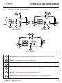
Remote port - Use this port to connect the optional remote control unit to the Inverter.
USB port - Use this port to connect a USB device.
Standard outlet - Use these sockets to connect AC loads to the Inverter.
Digital display - This display shows battery voltage and wattage.
ON / OFF - Use this button to turn the inverter ON or OFF.
Function LED - A single LED indicates Power (green) or Fault Condition (red).
GENERAL INFORMATION
2.3 MODIFIED HD FEATURES
D
E
F
C
B
A
NOTES
1
TYPE YOUR NOTES IN HERE
2
FEEL FREE TO MOVE/RESIZE THIS TABLE
REV
ECO #
DESCRIPTION
DATE
DRAWN BY
MATERIAL
FINISH
FINISH
SPEC
COLOR
D
C
B
A
A
B
C
D
1
2
3
4
5
6
7
8
8
7
6
5
4
3
2
1
TITLE
B
1:8
-
INVERTER, MSW, 5000W
1 OF 1
79227
SHEET
SIZE
REVISION
SCALE
DRAWING NO
CAD REFERENCE
Carmanah Technologies Corp.
250 Bay Street
Victoria, BC Canada V9A 3K5
Tel [250] 380-0052
Fax [250] 380-0062
CHANGES SHALL BE INCORPORATED
ELECTRONICALLY BY THE DESIGN AUTHORITY
PDM MAINTAINED DATA
COPYRIGHT © 2012 BY
Carmanah Technologies Corp. Victoria, BC, Canada
ALL RIGHTS RESERVED. NO PART OF THIS
DOCUMENT MAY BE REPRODUCED STORED IN A
RETRIEVAL SYSTEM, OR TRANSMITTED IN ANY
FORM, WITHOUT THE WRITTEN PERMISSION OF
Carmanah Technologies Corp.
PROPRIETARY
ORIGINALLY DESIGNED BY
ORIGINALLY DRAWN BY
CHECKED BY
DATE
DATE
DATE
Ben Jolie
Ben Jolie
12/13/2016
01/04/2017
UNLESS OTHERWISE SPECIFIED
DO NOT SCALE DRAWING
INTERPRET DIMENSIONS AND TOLERANCES
PER ASME Y14.100-2000
TOLERANCES APPLY AS SHOWN BELOW
DECIMALS SURF FINISH ANGLES
.X
.XX
.XXX
.XXXX
± .1
± .01
± .005
± .0005
63
1
INCHES
THIRD ANGLE PROJECTION
DOC #
DATE
21/12/11
57012
B
DOC REVISION
79227
ALL COMPONENTS AND PROCESSES TO BE ROHS COMPLIANT, CERTIFICATE REQUIRED WITH INITIAL SHIPMENT
NOTES
1
TYPE YOUR NOTES IN HERE
2
FEEL FREE TO MOVE/RESIZE THIS TABLE
REV
ECO #
DESCRIPTION
DATE
DRAWN BY
MATERIAL
FINISH
FINISH
SPEC
COLOR
D
C
B
A
A
B
C
D
1
2
3
4
5
6
7
8
8
7
6
5
4
3
2
1
TITLE
B
1:4
-
INVERTER, MSW, 3000W
1 OF 2
79222
SHEET
SIZE
REVISION
SCALE
DRAWING NO
CAD REFERENCE
Carmanah Technologies Corp.
250 Bay Street
Victoria, BC Canada V9A 3K5
Tel [250] 380-0052
Fax [250] 380-0062
CHANGES SHALL BE INCORPORATED
ELECTRONICALLY BY THE DESIGN AUTHORITY
PDM MAINTAINED DATA
COPYRIGHT © 2012 BY
Carmanah Technologies Corp. Victoria, BC, Canada
ALL RIGHTS RESERVED. NO PART OF THIS
DOCUMENT MAY BE REPRODUCED STORED IN A
RETRIEVAL SYSTEM, OR TRANSMITTED IN ANY
FORM, WITHOUT THE WRITTEN PERMISSION OF
Carmanah Technologies Corp.
PROPRIETARY
ORIGINALLY DESIGNED BY
ORIGINALLY DRAWN BY
CHECKED BY
DATE
DATE
DATE
Ben Jolie
Ben Jolie
12/13/2016
01/04/2017
UNLESS OTHERWISE SPECIFIED
DO NOT SCALE DRAWING
INTERPRET DIMENSIONS AND TOLERANCES
PER ASME Y14.100-2000
TOLERANCES APPLY AS SHOWN BELOW
DECIMALS SURF FINISH ANGLES
.X
.XX
.XXX
.XXXX
± .1
± .01
± .005
± .0005
63
1
INCHES
THIRD ANGLE PROJECTION
DOC #
DATE
21/12/11
57012
B
DOC REVISION
79222
ALL COMPONENTS AND PROCESSES TO BE ROHS COMPLIANT, CERTIFICATE REQUIRED WITH INITIAL SHIPMENT
NOTES
1
TYPE YOUR NOTES IN HERE
2
FEEL FREE TO MOVE/RESIZE THIS TABLE
REV
ECO #
DESCRIPTION
DATE
DRAWN BY
MATERIAL
FINISH
FINISH
SPEC
COLOR
D
C
B
A
A
B
C
D
1
2
3
4
5
6
7
8
8
7
6
5
4
3
2
1
TITLE
B
1:4
-
INVERTER, MSW 1750W
1 OF 1
79228
SHEET
SIZE
REVISION
SCALE
DRAWING NO
CAD REFERENCE
Carmanah Technologies Corp.
250 Bay Street
Victoria, BC Canada V9A 3K5
Tel [250] 380-0052
Fax [250] 380-0062
CHANGES SHALL BE INCORPORATED
ELECTRONICALLY BY THE DESIGN AUTHORITY
PDM MAINTAINED DATA
COPYRIGHT © 2012 BY
Carmanah Technologies Corp. Victoria, BC, Canada
ALL RIGHTS RESERVED. NO PART OF THIS
DOCUMENT MAY BE REPRODUCED STORED IN A
RETRIEVAL SYSTEM, OR TRANSMITTED IN ANY
FORM, WITHOUT THE WRITTEN PERMISSION OF
Carmanah Technologies Corp.
PROPRIETARY
ORIGINALLY DESIGNED BY
ORIGINALLY DRAWN BY
CHECKED BY
DATE
DATE
DATE
Ben Jolie
Ben Jolie
12/13/2016
01/04/2017
UNLESS OTHERWISE SPECIFIED
DO NOT SCALE DRAWING
INTERPRET DIMENSIONS AND TOLERANCES
PER ASME Y14.100-2000
TOLERANCES APPLY AS SHOWN BELOW
DECIMALS SURF FINISH ANGLES
.X
.XX
.XXX
.XXXX
± .1
± .01
± .005
± .0005
63
1
INCHES
THIRD ANGLE PROJECTION
DOC #
DATE
21/12/11
57012
B
DOC REVISION
79228
ALL COMPONENTS AND PROCESSES TO BE ROHS COMPLIANT, CERTIFICATE REQUIRED WITH INITIAL SHIPMENT
GP-1750HD GP-3000HD
GP-5000HD
B
F
D
B
F
D
C
C
C
E
E
E
A
D
F
A
8888
8888
8888
B
A

gpelectric.com | [page 11]
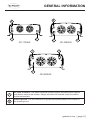
DC input connector - Use these connection points to secure the battery bank negative
and positive cables to the Inverter. Always ensure the DC terminal covers are used to
protect the terminals.
Chassis ground - Use this connection to ground the exposed chassis of the inverter to
the chassis ground.
GENERAL INFORMATION
NOTES
1
TYPE YOUR NOTES IN HERE
2
FEEL FREE TO MOVE/RESIZE THIS TABLE
REV
ECO #
DESCRIPTION
DATE
DRAWN BY
MATERIAL
FINISH
FINISH
SPEC
COLOR
D
C
B
A
A
B
C
D
1
2
3
4
5
6
7
8
8
7
6
5
4
3
2
1
TITLE
B
1:8
-
INVERTER, MSW, 5000W
1 OF 1
79227
SHEET
SIZE
REVISION
SCALE
DRAWING NO
CAD REFERENCE
Carmanah Technologies Corp.
250 Bay Street
Victoria, BC Canada V9A 3K5
Tel [250] 380-0052
Fax [250] 380-0062
CHANGES SHALL BE INCORPORATED
ELECTRONICALLY BY THE DESIGN AUTHORITY
PDM MAINTAINED DATA
COPYRIGHT © 2012 BY
Carmanah Technologies Corp. Victoria, BC, Canada
ALL RIGHTS RESERVED. NO PART OF THIS
DOCUMENT MAY BE REPRODUCED STORED IN A
RETRIEVAL SYSTEM, OR TRANSMITTED IN ANY
FORM, WITHOUT THE WRITTEN PERMISSION OF
Carmanah Technologies Corp.
PROPRIETARY
ORIGINALLY DESIGNED BY
ORIGINALLY DRAWN BY
CHECKED BY
DATE
DATE
DATE
Ben Jolie
Ben Jolie
12/13/2016
01/04/2017
UNLESS OTHERWISE SPECIFIED
DO NOT SCALE DRAWING
INTERPRET DIMENSIONS AND TOLERANCES
PER ASME Y14.100-2000
TOLERANCES APPLY AS SHOWN BELOW
DECIMALS SURF FINISH ANGLES
.X
.XX
.XXX
.XXXX
± .1
± .01
± .005
± .0005
63
1
INCHES
THIRD ANGLE PROJECTION
DOC #
DATE
21/12/11
57012
B
DOC REVISION
79227
ALL COMPONENTS AND PROCESSES TO BE ROHS COMPLIANT, CERTIFICATE REQUIRED WITH INITIAL SHIPMENT
NOTES
1
TYPE YOUR NOTES IN HERE
2
FEEL FREE TO MOVE/RESIZE THIS TABLE
REV
ECO #
DESCRIPTION
DATE
DRAWN BY
MATERIAL
FINISH
FINISH
SPEC
COLOR
D
C
B
A
A
B
C
D
1
2
3
4
5
6
7
8
8
7
6
5
4
3
2
1
TITLE
B
1:4
-
INVERTER, MSW, 3000W
1 OF 2
79222
SHEET
SIZE
REVISION
SCALE
DRAWING NO
CAD REFERENCE
Carmanah Technologies Corp.
250 Bay Street
Victoria, BC Canada V9A 3K5
Tel [250] 380-0052
Fax [250] 380-0062
CHANGES SHALL BE INCORPORATED
ELECTRONICALLY BY THE DESIGN AUTHORITY
PDM MAINTAINED DATA
COPYRIGHT © 2012 BY
Carmanah Technologies Corp. Victoria, BC, Canada
ALL RIGHTS RESERVED. NO PART OF THIS
DOCUMENT MAY BE REPRODUCED STORED IN A
RETRIEVAL SYSTEM, OR TRANSMITTED IN ANY
FORM, WITHOUT THE WRITTEN PERMISSION OF
Carmanah Technologies Corp.
PROPRIETARY
ORIGINALLY DESIGNED BY
ORIGINALLY DRAWN BY
CHECKED BY
DATE
DATE
DATE
Ben Jolie
Ben Jolie
12/13/2016
01/04/2017
UNLESS OTHERWISE SPECIFIED
DO NOT SCALE DRAWING
INTERPRET DIMENSIONS AND TOLERANCES
PER ASME Y14.100-2000
TOLERANCES APPLY AS SHOWN BELOW
DECIMALS SURF FINISH ANGLES
.X
.XX
.XXX
.XXXX
± .1
± .01
± .005
± .0005
63
1
INCHES
THIRD ANGLE PROJECTION
DOC #
DATE
21/12/11
57012
B
DOC REVISION
79222
ALL COMPONENTS AND PROCESSES TO BE ROHS COMPLIANT, CERTIFICATE REQUIRED WITH INITIAL SHIPMENT
NOTES
1
TYPE YOUR NOTES IN HERE
2
FEEL FREE TO MOVE/RESIZE THIS TABLE
REV
ECO #
DESCRIPTION
DATE
DRAWN BY
MATERIAL
FINISH
FINISH
SPEC
COLOR
D
C
B
A
A
B
C
D
1
2
3
4
5
6
7
8
8
7
6
5
4
3
2
1
TITLE
B
1:4
-
INVERTER, MSW 1750W
1 OF 1
79228
SHEET
SIZE
REVISION
SCALE
DRAWING NO
CAD REFERENCE
Carmanah Technologies Corp.
250 Bay Street
Victoria, BC Canada V9A 3K5
Tel [250] 380-0052
Fax [250] 380-0062
CHANGES SHALL BE INCORPORATED
ELECTRONICALLY BY THE DESIGN AUTHORITY
PDM MAINTAINED DATA
COPYRIGHT © 2012 BY
Carmanah Technologies Corp. Victoria, BC, Canada
ALL RIGHTS RESERVED. NO PART OF THIS
DOCUMENT MAY BE REPRODUCED STORED IN A
RETRIEVAL SYSTEM, OR TRANSMITTED IN ANY
FORM, WITHOUT THE WRITTEN PERMISSION OF
Carmanah Technologies Corp.
PROPRIETARY
ORIGINALLY DESIGNED BY
ORIGINALLY DRAWN BY
CHECKED BY
DATE
DATE
DATE
Ben Jolie
Ben Jolie
12/13/2016
01/04/2017
UNLESS OTHERWISE SPECIFIED
DO NOT SCALE DRAWING
INTERPRET DIMENSIONS AND TOLERANCES
PER ASME Y14.100-2000
TOLERANCES APPLY AS SHOWN BELOW
DECIMALS SURF FINISH ANGLES
.X
.XX
.XXX
.XXXX
± .1
± .01
± .005
± .0005
63
1
INCHES
THIRD ANGLE PROJECTION
DOC #
DATE
21/12/11
57012
B
DOC REVISION
79228
ALL COMPONENTS AND PROCESSES TO BE ROHS COMPLIANT, CERTIFICATE REQUIRED WITH INITIAL SHIPMENT
GP-1750HD GP-3000HD
GP-5000HD
1
2
2
1
2
1
1
1
1
2
1

[page 12] | gpelectric.com
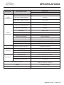
3. SPECIFICATIONS
Electrical Specication Item
Model No.
GP-1750HD
Input
Characteristics
Voltage Range 10.5 - 16 VDC
Input Over Voltage Protection 16.5 VDC
Input Under Voltage Protection 10 ± 0.5 VDC
No Load Current
≤1 A
Output
Characteristics
Continuous Output Wattage 1750 W
Maximum Surge Rating 3500 W
Frequency 60 Hz ± 3 Hz
Output Voltage 120 VAC RMS +5/-15
Efciency ≥80%
Short-Circuit Protection System Shutdown
USB Output Voltage 4.75 - 5.25 VDC / 2.1 A
Output Waveform Modied Sine Wave
AC Output Connections 3 Standard North American Outlets
USB Connections 1 USB Ports
Signal and
Control
Remote Controller Panel Unit GP-REMOTE (optional)
Protection
Input Protection Over / Under Voltage
AC Output Protection Short-Circuit, Overload
Others Over / Under Temperature Protection
Environment
Operating Temp. 32° F - 104° F (-0° C - 40° C)
Storage Temp. 14° F - 122° F (-10° C - 50° C)
Storage Temp. & Humidity 10 - 95% RH
Dimension (L x W x H)
8.07” x 8.86” x 3.50”
(205 mm x 225 mm x 89 mm)
Weight 6.42 lbs (2.91 kg)
Cooling Thermostatically Controlled Fan

gpelectric.com | [page 13]
SPECIFICATIONS
Electrical Specication Item
Model No.
GP-3000HD
Input
Characteristics
Voltage Range 10.5 - 16 VDC
Input Over Voltage Protection 16.5 VDC
Input Under Voltage Protection 10 ± 0.5 VDC
No Load Current
≤1.2 A
Output
Characteristics
Continuous Output Wattage 3000 W
Maximum Surge Rating 6000 W
Frequency 60 Hz ± 3 Hz
Output Voltage 120 VAC RMS +5/-15
Efciency ≥85%
Short-Circuit Protection System Shutdown
USB Output Voltage 4.75 - 5.25 VDC / 2.1 A
Output Waveform Modied Sine Wave
AC Output Connections 4 Standard North American Outlets
USB Connections 1 USB Ports
Signal and
Control
Remote Controller Panel Unit GP-REMOTE (optional)
Protection
Input Protection Over / Under Voltage
AC Output Protection Short-Circuit, Overload
Others Over / Under Temperature Protection
Environment
Operating Temp. 32° F - 104° F (-0° C - 40° C)
Storage Temp. 14° F - 122° F (-10° C - 50° C)
Storage Temp. & Humidity 10 - 95% RH
Dimension (L x W x H)
11.41” x 9.92” x 4.13”
(290 mm x 252 mm x 105 mm)
Weight 10.54 lbs (4.78 kg)
Cooling Thermostatically Controlled Fan

[page 14] | gpelectric.com
SPECIFICATIONS
Electrical Specication Item
Model No.
GP-5000HD
Input
Characteristics
Voltage Range 10.5 - 16 VDC
Input Over Voltage Protection 16.5 VDC
Input Under Voltage Protection 10 ± 0.5 VDC
No Load Current
≤1.2 A
Output
Characteristics
Continuous Output Wattage 5000 W
Maximum Surge Rating 10000 W
Frequency 60 Hz ± 3 Hz
Output Voltage 120 VAC RMS +5/-15
Efciency ≥80%
Short-Circuit Protection System Shutdown
USB Output Voltage 4.75 - 5.25 VDC / 2.1 A
Output Waveform Modied Sine Wave
AC Output Connections 4 Standard North American Outlets
USB Connections 1 USB Ports
Signal and
Control
Remote Controller Panel Unit GP-REMOTE (optional)
Protection
Input Protection Over / Under Voltage
AC Output Protection Short-Circuit, Overload
Others Over / Under Temperature Protection
Environment
Operating Temp. 32° F - 104° F (-0° C - 40° C)
Storage Temp. 14° F - 122° F (-10° C - 50° C)
Storage Temp. & Humidity 10 - 95% RH
Dimension (L x W x H)
18.50” x 9.92” x 4.13”
(470 mm x 252 mm x 105 mm)
Weight 15.65 lbs (7.10 kg)
Cooling Thermostatically Controlled Fan

gpelectric.com | [page 15]
4.1 INSTALLATION PRECAUTIONS
1.
Do not install the Inverter into a building’s electrical system. The Inverter is a vehicular
accessory. It is not designed to be safely used in a building’s electrical system and
has not been evaluated to meet building wiring codes. Improper application may
create a re or electric shock hazard.
2.
To allow proper cooling, install in an indoor well-ventilated area and do not cover ventilation
openings or cooling fans. Do not install in engine compartment. Avoid placing the
Inverter on carpets and rugs; they are not only ammable, but they also obstruct
vents underneath the Inverter.
3.
Keep combustible materials and gases away from the Inverter. The Inverter produces
sparks and heat during operation and could start a re.
4.
Connect to a 12 VDC power supply only. A power supply with lower voltage will not operate
the Inverter correctly, and higher voltage could damage the Inverter.
5.
Connect input polarity properly. Incorrect connection will damage the Inverter and void
warranty.
6. Keep the Inverter dry and clean. Do not expose to rain, snow, spray, bilge water, or dust.
7.
Use cables that are the appropriate size. The more power (amps) or the longer the cables,
the thicker they need to be to prevent overheating and re. See section 4.7 DC WIRING
SIZE.
8.
Install the Inverter as close to the DC source as possible, but not in a closed area with
vented lead-acid batteries. Vented lead-acid batteries release explosive hydrogen gas
that can be ignited by the Inverter.
9. Mount the Inverter horizontally.
10.
Verify that the installation surface has no hidden utility lines before drilling or driving screws.
11. This product is not a toy. Keep it out of reach of children.
12.
Do not use with positive ground electrical systems (most automobiles, trucks, and RVs
have negative ground systems).
13.
The positive (+) battery on the Inverter must be the last connection made, and must be
connected before the Inverter is turned on. There may be a small spark during the nal
connection. This is normal.
14. Properly ground the Inverter’s case as explained in this manual.
4. INSTALLATION

[page 16] | gpelectric.com
INSTALLATION
4.2 INVERTER SHUTDOWN
The Inverter has a number of shutdown points, for the safety of the operator, the Inverter,
and the devices being used with it.
•
If the DC input voltage drops too low, the alarm on the Inverter will sound. If the
input voltage drops further, the Inverter will shut down automatically to prevent
permanent battery damage. Recharge the battery as soon as possible.
•
If the DC input voltage exceeds 16 VDC, the Inverter will shut down automatically.
• If the output load power rises higher than the rating power of the Inverter, the
Inverter may shut down automatically.
•
The Inverter may automatically shut down if its internal temperature gets too high.
Note: even though this Inverter has built-in mechanisms to minimize damage, these situations
should be avoided because they can still damage the Inverter or battery.
4.3 WHERE TO INSTALL
Your Inverter should be installed in a location that meets the following requirements:
1. Dry: do not allow water to drip or splash on the Inverter.
2. Cool: ambient air temperature should be between 0°C and 40°C (the cooler the better).
3. Ventilated: allow at least two inches of clearance around the inverter for airow. Ensure
the ventilation openings on the rear and bottom of the unit are not obstructed.
4.
Safe: do not install the Inverter in the same compartment as batteries or in any compartment
capable of igniting ammable liquids such as gasoline.
5. The Inverter should be located within 10 feet of the batteries.

gpelectric.com | [page 17]
4.5 INSTALLATION AND TESTING
Battery Type Selection:
• Use only deep-cycle lead-acid batteries with this Inverter, such as 12 volt ma-
rine/RV deep-cycle batteries. Do not use automotive, engine starting (SLI),
or maintenance-free wet cell batteries with this Inverter; they are designed for
repeated, shallow discharge and will wear out quickly.
•
Gel and AGM (Absorbed Glass Mat) batteries can be used with this Inverter, but
they require special charging procedures. Refer to battery supplier’s instructions.
1. Unpack and inspect the Inverter, and make sure the power switch is in the OFF position.
Note: we recommend using Go Power! DC Install Kits when installing a Go Power! Inverter
(sold separately). Check section 4.7 DC WIRING SIZE to determine what Install Kits works
for your Inverter.
2. Connect the DC Inverter cables into the power input terminals on the back of the Inverter.
Remember, the (+) terminal is positive and the (-) terminal is negative. Place the lug
connector between the washers and tighten the terminal screw or nut to clamp the wires
securely. Ensure connections are tight.
3. Connect the ground cable to the appropriate location; see section 4.8 GROUNDING.
INSTALLATION
4.
First, connect the DC Inverter cables from the negative terminal of the Inverter to the
negative terminal of the battery. Make sure the connection is secure.
5. Before proceeding further, carefully check that the cable you just connected is going from
the negative terminal of the Inverter to the negative output terminal of the battery.
6. Install the Inverter fuse into the positive lead. The fuse should be located within 12” (31
cm) of the battery. Ensure all connections are tight and secure.
7.
Connect the cable of the positive terminal of the Inverter to the positive terminal of the
battery. Make a secure connection. Check your polarity.
CAUTION! Equipment Damage.
Loose connections result in excessive voltage drop and may cause
overheated wires and melted insulation. Ensure connections are tight.

[page 18] | gpelectric.com
INSTALLATION
CAUTION! Equipment Damage.
This Inverter cannot supply power to any AC distribution wiring or AC
loads in which the neutral and ground are connected (bonded). Doing
so will destroy the unit and void the warranty. If you do not understand
neutral to ground bonding, please have a professional install your system
for you. See section 4.8 GROUNDING for more information.
WARNING! Fire/explosion Hazard.
You may observe a spark when you make the nal battery connection
since current may ow to charge capacitors in the Inverter. Do not make
this connection in the presence of ammable fumes, as explosion or
re may result.
8.
Set the power switch to the ON position. Check the meters and indicators on the front
panel of the Inverter. The Function LEDs should be green showing the Inverter is ON.
If it does not, check your battery bank and the connections to the Inverter. The other
indicators should be OFF.
9. Set the Inverter switch to the OFF position. The indicator lights may blink and the internal
alarm may sound momentarily. This is normal. Plug the test load into the AC receptacle
on the front panel of the Inverter.
10.
Set the Inverter switch to the ON position and turn the test load on; the Inverter should
supply power to the load. If you plan to measure the output voltage of the inverter, a true
RMS meter must be used for accurate readings.

gpelectric.com | [page 19]
4.6 BATTERY PRECAUTIONS
1.
Wear splash-resistant ANSI-approved safety goggles and electrically-insulated gloves
while working near batteries.
2. Charge, store, and maintain batteries according to supplier’s instructions.
3.
Locate batteries in a clean, well-ventilated area, away from ignition sources and ammable
materials. Vented lead-acid batteries release explosive hydrogen gas while charging.
4.
Only connect similar batteries together. Do not connect old and new batteries together,
ooded and gel cells together, or batteries of different capacities together.
5.
Only connect this Inverter to a 12V nominal battery bank. Do not attempt to connect
the Inverter to any other power source other than a battery with a nominal output
voltage of 12 volts or damage to the Inverter may occur and will void the warranty.
6.
Connect batteries in parallel ONLY (negative terminals together to one cable; positive
terminals together to the other cable).
7. Install a properly rated fuse on the positive output of the battery bank. See section
4.7 DC WIRING SIZE.
The following points must be observed for the DC Wiring.
• The DC positive and negative cables connected to the Inverter from the battery
bank should be linked together with zip ties or electrical tape every 6”. This helps
to reduce radio frequency interference and reduces the effects of inductance both
of which improve the Inverter waveform and reduces the wear of the Inverters
lter capacitors.
•
To ensure optimum Inverter performance the number of connections between
the battery bank and the Inverter unit should be minimized except from the
over-current and battery disconnect devices. All additional connection points
will cause extra voltage drops.
• The Battery bank voltage must match the DC voltage required by the Inverter,
which is 12V.
•
All DC cable wire terminations should use a crimped and sealed copper ring
terminal lugs.
• Make sure all cables have a smooth bend radius and no kinks are present.
•
Colour code all DC Cables coming to/from the battery bank. Use coloured
electrical tape or heat shrink tubing. Red for positive (+), Black for negative (-)
and Green for DC ground.
INSTALLATION

[page 20] | gpelectric.com
12 V
Lead-acid
Battery
OUTPUT
(to Inverter
Negative
Terminal)
OUTPUT
(to Inverter
Positive
Terminal)
12 V
Lead-acid
Battery
To increase
capacity,
connect
additional
12 V
Lead-acid
batteries
INSTALLATION
4.7 DC WIRING SIZING
The distance between the battery bank and the Inverter should be as short as possible to
achieve maximum efciency and to reduce re hazards. The gauge of the cable should be
sized appropriately to limit the voltage drop to less than 2% when carrying the maximum input
current to prevent frequent low-input voltage warnings and shutdown. Only use high quality
copper wire.
The cables should be as short as possible and the overall length of both cables added together
should be less than 10 ft (3 m) to comply with code requirements. Keeping your wire runs as
short as possible helps to prevent: low voltage shutdowns and nuisance tripping of the DC
breaker because of increased current draw. The table below shows the recommended DC
cable size, fuses/circuit breakers and DC grounding cable sizes for the Inverter (note: these
values are correct for cables in free air, not conduit).
Model Wire AWG Inline Fuse / Circuit Breaker
GP-1750HD #2 F-200
GP-3000HD 4/0 F-400
GP-5000HD 4/0 F-400
Page is loading ...
Page is loading ...
Page is loading ...
Page is loading ...
Page is loading ...
Page is loading ...
Page is loading ...
Page is loading ...
Page is loading ...
Page is loading ...
-
 1
1
-
 2
2
-
 3
3
-
 4
4
-
 5
5
-
 6
6
-
 7
7
-
 8
8
-
 9
9
-
 10
10
-
 11
11
-
 12
12
-
 13
13
-
 14
14
-
 15
15
-
 16
16
-
 17
17
-
 18
18
-
 19
19
-
 20
20
-
 21
21
-
 22
22
-
 23
23
-
 24
24
-
 25
25
-
 26
26
-
 27
27
-
 28
28
-
 29
29
-
 30
30


Go Power GP-3000HD User manual
- Category
- Power adapters & inverters
- Type
- User manual
- This manual is also suitable for
Ask a question and I''ll find the answer in the document
Finding information in a document is now easier with AI
Related papers

Other documents
-
 Nature Power 50183 Owner's manual
-
Dometic GP-IC-2000 User manual
-
 Go Power! Electric GP-3000 User manual
-
 Nature Power 37750 User manual
-
ADJ PL-1001ETL Operating instructions
-
 Nature Power 37750 Owner's manual
-
 POTEK 10 User manual
-
 Go Power! GP-IC2000-12-PKG User manual
-
Carmanah MX SERIES Installation guide
-
 AIMS PWRINV5K24012W User manual


