Barco IOSONO CORE User guide

Type
User guide
IOSONO CO RE
Installation And U ser M anual
R9801500 - R9801502
R9801503 - R9801504
R5906746/00
08/05/2017
Barco Audio Technologies
Erich-Kästner-Str. 1a, 99094 Erfurt, Germany
Phone: +49 361 51143 670
Fax: +49 361 51143 677
Support: www.barco.com/en/support
Visit us at the web: www.barco.com
Barco NV
Beneluxpark 21, 8500 Kortrijk, Belgium
Phone: +32 56.23.32.11
Fax: +32 56.26.22.62
Support: www.barco.com/en/support
Visit us at the web: www.barco.com
Printed in Belgium
Changes
Barco provides this manual ’as is’ without warranty of any kind, either expressed or implied, including but not limited to the implied w ar-
ranties or m erchantability and tness for a particular purpose. Barco may make improvements and/or changes to the product(s) and/or the
program(s) described in this publication at any time without n otice.
This publication could c ontain technical inaccuracies or typographical errors. Changes are periodically made to the information in this
publication; these c hanges are incorporated in new editions of this publication.
The latest edition of Barco manuals can b e downloaded from the Barco web site w
ww.bar co.com or from the secured Barco web site
h
ttps://www.barco.com/e n/signin.
Copyright ©
All rights reserved. No part of this document may be copied, re produced or translated. It shall not otherwise be r ecorded, transmitted or
stored in a retrieval system without the prior written consent of Barco.
EN55022/CISPR22 Class A ITE (Information Technology Equipment)
Class A ITE is a category of all other ITE w hich satises the class A ITE limits but not the class B IT E limits. S uch equipment should not
be res tricted in its sale but the following warning shall be included in the ins tructions for use:
Warning: This is a class A product. In a dom estic environment this product m ay cause radio interference in which case the user may be
required to take adequate measures.
Guaran tee and Compensation
Barco provides a guaran tee relating to perfect manufacturing as part of the legally stipulated t
erms of guarantee. On receipt, the pu rchaser
must immediately inspect a ll delivered goods for damage incurred during transport, as well as for material and manufacturing faults Barco
must be informed im mediately in w riting of any c omplaints.
The period of guarantee begins on the date of transfer of risks, in the case of special systems and software on the date of c omm issioning,
at latest 30 days after the transfer of risks. In the event of justied notice of com plaint, Barco can repair the fault or provide a replacement
at its own discretion w ithin an appropriate period. If this measure proves to be impos sible or uns uccessful, the purchaser ca n demand a
reduction in the purchase price or cancellation of the contract. All other claims, in particular those relating to com pensa tion for direct or
indirect damage, and also damage attributed to the operation of s oftware as well as to other services provided by Barco, being a component
of the system or independent service, will be deemed invalid provided the dam age is n ot pro ven to be attributed to the absence of properties
guaranteed in writing or due to the intent or gross negligence or part of Bar co.
If the purchase r or a third party carries out modications or repairs on goods delivered by B arco, or if the goods are handled incorrectly,
in particular if the s ystem s are operated incorrectly or if, after the transfer o f risks, the goods are subject to inuences not agreed upon in
the contract, all guaran tee claims of the pur chaser will be rendered invalid. Not included in the guarantee co verage are system failures
which are attributed to programs or s pecial electronic circuitry provided by the purchaser, e.g. interfaces. Normal wear as well as normal
maintenance are not subject to the guarantee p rovided by Ba rco either.
The environmental conditions as well as the servicing and maintenance regulations specied in this manual must be com plied with by the
customer.
Disclaimer Of Warranty: This software and t
he ac companying les are s old as is and without warranties as to performance or mer-
chantability or any other warranties whether express ed or im plied. In no event shall Barco be liable for damage of any kind, loss of data,
loss of prots, business interruption or other pecuniary loss arising directly or indirectly. Any liability of the se ller will be e xclusiv ely limited
to replacement of the product or refund
of pur chase price.
Trademarks
Brand and pr oduct names mentioned in this manual may be trademarks, registered trademarks or c opyrights of their respective holders.
All br and and product names mentioned in this man ual serve as com men ts or examples and are not to be understood as advertising for
the products or their manufacturers.
1. Introduction
1. INTRODUCTION
1.1 About This Manual
About This Manual
This manual is subject to the copy right of Barco N .V. All exploitation, publication, reproduction
or distribution in w hole or in part is
forbidden without the prior written permission of Barco N.V..
All rights created by patent gr ant or registration of a utility model or design patent are r eserved. The manufacturer reserves the right
to a mend this manual at any time and without notice as result of technical progress.
This manual is applicable to the IOSONO CORE and the s oftware comp onents Easy Control a nd Control Unit.
Read through this manual thoroughly before using the IOSONO CORE in order to avoid m istakes and dangers, and to inform y ourself
about how to use the system safely.
R5906746 IOSONO CORE 08/05/2017
1
1. Introduction
2 R5906746 IOSONO CORE 08/05/2017
2. Safety
2. SAFETY
About This Chapter
Read this chapter thoroughly before attempting to install or operate the IOSONO CORE.
To prevent personal injury to users or physical damage to the IOSONO CO R E while installing and using it, ens ure that you under-
stand and follow all safety guidelines, instructions and warnings included in this chapter and this manual.
Overview
General Co nsiderations
Important Safety Instructions
2.1 General Considerations
General Considerations
The IO SO NO CO RE is designed for installation in control cabinets. T he IOSONO C OR E is a high-performance audio processor
used to drive and congure a B ARCO IOSONO sound system.
The IOSONO CORE and all associated components may only be used if they are in p erfect, technical working order, and for t heir
intended purpose, with safety in mind and an aw areness of the dangers, and as stated in this manual.
The IOSONO C OR E is operated via a gr aphic user interface. Reference is made to the currently valid guidelines for w orking with
a visual display unit.
There are add itional documents for other components of the so und system containing warning, safety and working instructions.
These instructions must be observed independently to this manual.
2.2 Important Safety Instructions
About
The IOSONO CORE offers an ex tremely high level of safety if u sed properly and in com pliance with the instructions contained
in this man ual. Read and comply with the following safety instructions before operating the device. Retain safety an d operating
instructions for future reference. Adhere to all warnings on the device and in the operating instructions manual. Follow all instructions
for operation and use.
Installation
The device may only be installed and operated by a
uthorized, suitably qualied personal. More advanced c ongurations of the
apparatus m ay only b e made by skilled personnel with k nowledge of sound technology.
Place the device on a at, solid and stable surface or x the device to an appropriate rack mounting system that can support the
total weight of the device. If you use an unstable car t or stand, the device may fall, causing serious injury to a child or adult and
serious damage to the device.
Modications To The Unit
Do not modify this equipment without authorization of the manufacturer. No serviceable pa rts inside.
Electric shock or re hazard
To prevent electric shock or re haz ard, do not remove cover. Do not inse rt any objects through aperture in the c asing.
Power connection and transient ov er voltage
To avoid the risk of electric shoc k, this equipment mu st on ly be connected to s upply mains with protective earth.
The equipment should be installed near an easily ac cessible outlet.
The equipm ent is intended for continuous o peration.
If the device is not used for long time, disconnec t it from the AC inlet to avoid d amage by transient over-voltage.
To fully disengage the power to the dev ice, please disconnect all power cords from the AC inlets.
Power Cords
Please always use the power cords provided with the product. Furthermore, make sure that the us ed power cord always corresponds
to the voltage of the power socket, is permitted to b e used at your loca tion and complies with the safety standards of y our country.
Do not overload wall outlets and ex tension c ords as this may result in re or e lectric shock.
R5906746 IOSONO CORE 08/05/2017
3
2. Safety
Mains lead protection (U.S.: Power cord): Power cords should be routed so that they are not likely to be walked upon or pinc hed
by items placed upon or against them, paying particular attention to cords at plugs and receptacles. The power supply cords s hould
be replaced by the designated ope rator only at all times.
Water and Moisture
Never expose the device to rain or m oisture. Never use the device near water e.g. near a swim ming pool.
Ventilation
Inadequate heat dissipation can lead to hardware faults and loss of d ata. Do no t cover or block any ventilation openings in the side
and back of the set. When installing the device in a cupboard or an other closed location, heed the nec essary space between the
set and the s ides of the cupboard. If n ecessary, consider additional ex ternal cooling, to ensure proper heat dissipation.
Material damage caused by electromagnetic elds
The apparatus contains parts s ensitive to electromagnetic elds, like hard disc drives. Strong m agnetic elds m ay lead to loss of
data or harm the system functionality partly o r persistently. Do not place the apparatus within t
he range of strong magnetic elds.
The manual and the hard ware and software components described hav e been produced according to the currently applicable state
of the art. Nevertheless, the pr oducts described ar e continually being further developed so that we have to reserve the right to make
changes to the form, equipme nt an d technology of the sc ope of supply and the software compo nents included.
Barco N .V. s hall not be liable for any dam age arising from the use of the documentation or the hardware and software components.
No claims for changes to products already supplied can be asserted on the bas is of the statements, illustrations and descriptions in
this documentation.
Barco N.V. shall not accept any liability for conse quences or damages arising from improper use of the dev ice. Unauthorized modi-
cations to the hardware or software conguration shall exclude liability for dam age resulting therefrom.
4
R5906746 IOSONO CORE 08/05/2017
3. Hardware
3. HARDWARE
Overview
Front P anel
Rear Panel
3.1 Front Panel
Front Panel
The front panel contains the following elements:
3
2
1
Image 3-1
IOSONO CORE front panel
Item No. Function
1 Power button
2 Volum e c ontrol
3 Touch screen
3.2 Rear Panel
Rear Panel
1
2
3
4
5
6
7
8
9
Image 3-2
IOSONO COREE rear view
Number and kind of audio d rawers depends on IOSONO CORE conguration. For detailed information about connections and
available h ardware options see "Technical Specications", page 59.
R5906746 IOSONO CORE 08/05/2017
5
3. Hardware
Item No. Element Element
1
USB connectors Connection of USB storage devices for sy stem back up and restore. Firmware update
2 MAIN ethernet port
Network connection to remote computer to control and se tup the IOSONO CORE with
the Control Unit software
3 AUX ethernet port Not used
4
COM port
Media control
5
Sync drawer Input and output of different sync s ignals
6 MADI drawer Electrical and op tical MADI input and output connections
7
AES drawer Electrical AES inputs and output connections
8 Blind drawer
-
9 Power supply
Power supply of the IOSONO CO RE
6 R5906746 IOSONO CORE 08/05/2017
4. System Startup
4. SYSTEM STARTUP
4.1 Initi al Operation
Initial O peration
Your IOSONO CORE consists of electronic parts that may be sensitive to variations in temperature an
d humidity. Suc h variations
could appear with changing the place of installation or by leaving the device unused for a longer period of time.
To avoid harm to the device, always leave your device un powered for a while. This should climatize the IOS ONO CORE a nd its
hardware components to a no rmal working condition.
Initial Connection
Depending to y our device hardware congu ration, IOSONO CO RE consists of single or redundant power supply compo nent. Before
powering your de vice ensure each main inlet has b een connected to your local power circuit orderly an d in consideration of local
law and technical policies.
Please note: In case of local power circuit failure, redu ndant p ower s upply will only get effective whe n inlet of redundant power
supply is or derly connected to a redu ndant local power circuit.
Based on your application connect all needed audio and data con nections to the system now. A description of the device connectors
could be found at image 3- 2. For proper operation always ens ure sufcient c onnections. Alway s use cables and connectors that
matches your applications need with respect to type, dimens ion a
nd quality.
Power On
systems featuring redundant power supply, please activate each of both power switches available.
Deactivate each main power switch if system is unused for longer period of time. Always deactivate each main power s witch before
disconnecting the system from local pow er c ircuit.
Your IOSONO CORE is now ready to be started. In ord er to pow er on IOSONO CORE, please push the power button like shown at
Figure 3.1. The power button is now illuminated, indicating dev ice is powere d and running.
4.2 Basic System Control
About
Your IOSONO CORE is controlled via control software named "Control Client". T he Control Client connec ts a M S W indows com puter
remotely to the IOSON O CORE processor. For installation details, please r efer to the Quick Start G uide that has been delivered
with your product.
Connect to IOSONO CORE Control Unit or to Easy Control by pus hing the b utton respectiveley. The Control Unit gives you an
extended access to available congurations of the IOSONO CORE. The Easy Control gives you access to the mos t important con-
gurations and preset controls. All settings of Easy C ontrol are ac cessible using IOSONO CORE tou ch interface (image 3 -1).
4.2.1 Get System Control
Get System Control
1. Set up a network connection between the remote co mputer and the IO SONO CO RE (M ain Port). Congure the rem ote com-
puter’s network interface IP adress to the same network as the IOSONO COR E. By factory default, device network is set to be
IP 192.168.1.1, Network mask: 255.255.255.0 .
For example: Static IP of remote computer is 19 2.168.1.2.
2. Start the Control Client at your remote c omputer. Conn ect to the target device us ing the corresponding target IP address.
R5906746 IOSONO CORE 08/05/2017
7
4. System Startup
Image 4-1
Control Client
4.2.2 File Transfer
File Transfer
Files can be trans mitted via the Control Client using the folder bu tton in the lower right c orner. The button opens a le browser. In
the le browser, the left half shows the le s tructure of remote computer while the right half shows the accessible IO SONO CO RE
le structure.
Upload and download les and folders from the remote computer to the IOSON O CO RE and v ice versa using the appropriate com-
mands of the context menu. Create your own folders and directories
at the IOSONO CORE le system . This will easier your workow
at minimum in case of le mana gement for
Content distribution and import
System bac kup and restore
•Conguration Of Your Show An d Venue
System upda te management
4.2.3 Factory Reset
Factory Reset
Clear user data and/or restore factory conguration using the arrow button in the lower right corner of the Control Client window.
Use the check boxes to select the reset options - you hav e to complete by entering the randomly generated character string.
It is recom mended to restoring factory settings of your device whe
never the IOSONO CORE is not working properly. In such cas e
of faulty settings, any reset will reload the factory settings or restore a previously created backup.
4.2.4 Touchscreen Interface & Easy Control
Touchscreen Interface & Easy Control
Your IOSO NO CORE includes an integrated 7 pressure sensitive touch screen interface (image 3-1). By pushing the focuse d area
on the screen, you can directly access the control elements of "Easy Control". Easy Control is a graphic interface to easily ac cess
all basic settings of your device and your show. The easy con trol interface is even more ac cessibly remotely using the IOSO NO
CORE Control Client (Please see "File Transfer", page 8 ) .
An overview of E asy Control and its control elements is outlined following.
8
R5906746 IOSONO CORE 08/05/2017
4. System Startup
1
2
3
4
5
6
7
Image 4-2
Easy Co ntrol user interface
Item No. Function Result
1 STOP button The active preset is stopped
2 MUTE button The active preset is muted
3Conguration button The conguration display is activated
4 Information button Call detailed information about the software v ersion
5
LOG button The log lesoftheIOSONOCOREcanbestoredona
USB s torage dev ice c onnected to one of the IOSO NO
CORE USB ports
6 Network button
Enter the network conguration of the Main Ethernet
Port:
Activate DHCP by pressing D HCP ON
•Setax ed IP address and subnet m ask when
DHCP is off
Reboot the IOS ON O COR E to apply changes or
press Cancel to restore the previous conguration
7 Preset selection list
Preset buttons are labeled with the name of the related
preset. When pressed, that preset will be started. P ress
the left/right arrows to go to previous / next page of the
selection list.
R5906746 IOSONO CORE 08/05/2017 9
4. System Startup
10 R5906746 IOSONO CORE 08/05/2017
5. Initial System Configuration
5. INITIAL SYSTEM CONFIGURATION
5.1 Hardware Connections
About
To enter the C ontrol Unit and make congurations, a remote computer (PC with Windows, laptop, ...) w
ith Control Client installed and
ethernet c onnection between rem ote computer and IOSONO C OR E is need ed. Please see "System Startup", page 7 for further
details.
A standard system setup should be similar to the wiring s cheme as shown in image 5-1.
Image 5-1
Standard wiring with 64 output channels via M ADI
Start the Control Client, type in the target IP address of the IOSO NO CO RE a nd click on Connect. Enter the Control Unit software,
type in the pass word and click OK to conr m. The default password is )))
5.2 Create A Loud speaker File
About
A loudspeaker le is always needed to setup presets or to ex ecute the rendering process. It has to r eect the real loudspeaker
setup as c losely a s possible. A ny deviation between the actual physical setup and the le will impair the rendering precision a nd the
overall sound qua lity. In this sec tion w e will describe how to create a loudspeaker le with example v alues.
To create a loudspeaker le for your ac tual setup y ou need to use real da ta.
Step-By-Step Guide
1. In the m enu go to S ystem - Options - Loudspeaker Setups - Create. A window is shown like in image 5-2.
2. Name your loudspeaker setup, for example 3D ls le
- Change A udience Area Height to 1.20m
- Keep all other default settings in the second line (Screen, System Offset and Reference Point)
Note: The audience area de nes the area where the audience will be located. The height of the audience area refers to the
average ear level of the audience, which is usually 1.20m when seated and 1.70m when standing.
3. Create a speaker group with + in Groups
R5906746 IOSONO CORE 08/05/2017
11
5. Initial System Configuration
- Keep Type Rectangle
- Name your group, e.g. Ring
- Click OK to conrm (image 5-3)
4. Back in ma in window: in Group Type keep Multilayer checked, keep default Width and Length in Dimensions and type 1.5m
in Height (value desc ribes the absolute installation height of the speakers’ acoustical center above ground).
5. Loudspeakers
- Front: 7
-Rear:5
- Left: 7
-Press> between Left and Right for Right to copy the entered date from Left
6. Create a new group with + in Groups
- Choose Type Surface from the drop down menu
- Name your group, e.g. Ceiling
-PressOK to conrm (image 5-4)
7. Keep Multilayer checked and type in Su rface Height 3m (value is the absolute h eight of this group above ground). Add 4 mo re
lines by processing + 4 times
- Type in line 1: Loudspeakers 4
- Line 2: Lou dspeake rs 3
- Line 3: Lou dspeake rs 4
- Line 4: Lou dspeake rs 3
- Line 5: Lou dspeake rs 4
- Distance X keep default value (1m)forline1-5
- Distance Y type 1.5m forline1-5
8. Create a new group with + in groups
- Keep Type Rectangle
- Name your group, for exam ple Subwoofer
- Click OK to conrm
9. Check S ubwoofer in group type
- Dimensions: Height 0.5m (value describes the abso lute installation height of the speakers’ acoustical center above ground)
- Loudspeakers -
Front 2, Left/Right S p acer 1.5m
- Rear 1, Rig ht Sp acer 2.5m (with a dimensions width of 5m the rear subwoofer w ill be half-way of the width in the r ear c enter)
10.Press OK to create the loudspeaker le
Note: Using this tool you can create many different loudspeaker les, including standard setup types such as 2.0, 5.0, 7.0 as
well as m ultilayer s etups, s imply by adding more groups with different height values. T he layers will be automatically
organized in ascending order based on their average height information.
11.The 3D ls le is displayed in layers at Options menu (left: top view, right: le name). Choos e the layer to be displayed u sing the
drop-down menu Loudspeaker G roup. Figure 5.5 visualizes the loudspeaker setup previously created with the Setup Des igner.
(image 5-5)
12.D ene Zones to ensure correct reproduction of zone objects, the c orresponding zones need t
obedened in the loudspeaker
setup. Zones can be dened individually for each loudspeaker setup as a property of th e specic setup.
Make sure you are at menu System - Options - Loudsp eaker Setup s
- Select the loudspeaker setup in w hich you w ant to dene Zones
- Click on Edit
- Click on the Zone m ode Icon in the lower left cor ner
- Click on Zone A ssignment
- Select the loudspeaker(s) for the r st assignment
- From the right list, select the Zone ID you want the selected loudspeakers to be as signed to
- Repeat until at least on louds peaker is ass igned to each of the desired Zones
- When you have nished with Zones denition, exit the edit mode by clicking Edit again.
Note: Multiple loudspeakers can be selected by holding shift+click or cmd+click
Note: Loudspeakers c an be assigned to Multiple Zones in c ase several Z one Objects should be reproduced by the same loud-
speaker. For example the Zones left s urround and left back surround need to be reproduced using a single loudspeaker
present left to venue.
13.Press Export to save your loudspeaker setup le for backup purposes
- Create a new directory in the Export dialog using the icon F older. As an example nam e it
to Ls Files and save your loud-
speaker le to the directed folder as lpee type *.ls4
Note: Save your
le as le type *.ls3 for being compatible with previous system generations such as the IPC100. Som e features
exclusive to the IOSO NO CORE will n ot be contained to *.ls3
12
R5906746 IOSONO CORE 08/05/2017
5. Initial System Configuration
14.Press OK to leave the Options m enu
Image 5-2
Create Loudspeaker Setup view
Image 5-3
Create a rectangular group
R5906746 IOSONO CORE 08/05/2017 13
5. Initial System Configuration
Image 5-4
Create a surface g roup
Image 5-5
Simple 3D model of a created loudspeaker setup
5.3 Create A Test Preset
5.3.1 Noise
About
In this chapter a new preset will be created as preparation for running a line check to all connected signal compon ents.
14
R5906746 IOSONO CORE 08/05/2017
5. Initial System Configuration
Step-By-Step Guide
1. Press New and assign a Preset Name for examp le Noise
- Click OK to conrm
2. The view switches to the Preset Details tab with a tree structure on the left. Keep default values in G eneral, make sure that in
Loudspeaker Setup the previously created loudspeak er setup le 3D ls le is selected from the dropdown men u and Visibility
has a c heck.
Ignore Filtering for the time being. An adv anced explanation is given within Section "Filter Creation", page 23. Ensure the
IOSONO C OR E is the us ed device right haveing a look to Dev ices and Services.
3. In IOSONO CORE select Processing an d I/O Co ntrol from A vailable Se rvices and as sign to Used Services with <
4. In the tree structure, go to I/O C ontrol - Congurati on and c lick Autodetect. The displayed conguration should match yo ur
purchased hardware conguration with the IOSONO CO RE (regarding I/O C ong M, 1x MADI s hould be selected)
-InSynchronization,pressInternal
5. Inthetreestructure,gotoProcessing and select the following in the General tab for Renderer. When done, cli
ck OK to conrm
the warning message
-Active
- Auto Conguration
Note: The software creates three render s lots automatically. T his is due to ea ch loudspeaker le consists of 3 loudspeaker
groups ("Ring", "Ceiling","Subwoofer"). Within our example we want to use th e a utomatically congured settings for these
render slots. The loudspeaker group
Ring us es IOSONO in Algorithm Selection, Ceiling uses Panning in Alg orithm Selection and 3D / Ce iling in Geom-
etry Mode and Subwoofer uses Panning in Algorithm Selection an d 2D / Surface in geo
metry mode.
To allow bass ma nagement, check Loudspeaker Extension in Ring at Slo t Setti ngs - Subwoofer
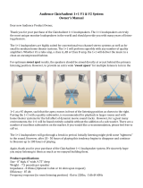
6. In the General tab, click Active in Noise and ch eck A utostart. A new tab Noise a ppears a bove. (image 5-6)
7. Go to Output Routing tab
Note: In the matrix, the rows represent the loudspeakers of your louds peaker s etup that are ass igned to render slots, each with
an individual color. The columns represent physical au dio outputs of the processor, which can be acces sed at the rear of
your IOS ONO CO RE ha rdware. You may congure your individual output routing h ere. In our example, speakers 1-15 in
render slot 1 are connected to outputs 1-15 (dummy speakers 16 and 17 require no connec tion to physical audio ou tputs),
speakers 1-4 in render slot 2 are connected to outputs 18-21, speakers 1-2 in render slot 3 are co nnected to outputs
22-23 and speakers 1-5 in render slot 4 are connected to outputs 24-28. T herefore we want to use the automatically
cong ured diagonal 1-to-1 routing.
8. Turn down the Main Volume to -inf dB by holding - in the upper r ight corner. To s
tart th e p rese t , click Run in the upper left corner.
Note: The button as well as the status lights of Audio I/O Control and P rocessing s hould get a gr een halo.
9. Go to the Noise tab
- Set the maximum volume of the noise sequence with the Volume Fader
- Click Play with the Loop Icon
- To s tep through all speakers of each louds peaker group, sequently
sele ct All Groups in Seq uence
- To step through all speakers of a single louds peaker group only select Single Group in Sequen ce with group name
- To step through loudspeakers manua lly click Forward / Backw ards button
Note: In the display y ou c an see that the noise sequence steps through the selected speakers according to the noise signal
sequence.
10.Go to Audio I/O Control in the tree structure and press Status icon
- At the m ain window, turn up the Main Volume with + in the upper right corner
- The am plitude of level m eters in Processing and Output will rise with increasing volume and a full range pink noise becomes
audible on the r espective speaker (im age 5-7)
Note: It is advisable to carefully check each output channel for sen ding a signal to the expected speaker. If the step sequence
is too fast or you wan t to listen to single groups more c losely, you can change playbac k settings in Preset Details -
Processing - Noise - Tool icon. Continue when you’re done with s ignal che ck for all speakers.
11.Go to Preset list by clicking the List ic on, select the Noise preset and save it
R5906746 IOSONO CORE 08/05/2017
15
5. Initial System Configuration
- Click Stop in upper left corner of main window
Image 5-6
Processing settings (noise)
Image 5-7
Audo I/O Control status view
16 R5906746 IOSONO CORE 08/05/2017
  • Page 1 1
  • Page 2 2
  • Page 3 3
  • Page 4 4
  • Page 5 5
  • Page 6 6
  • Page 7 7
  • Page 8 8
  • Page 9 9
  • Page 10 10
  • Page 11 11
  • Page 12 12
  • Page 13 13
  • Page 14 14
  • Page 15 15
  • Page 16 16
  • Page 17 17
  • Page 18 18
  • Page 19 19
  • Page 20 20
  • Page 21 21
  • Page 22 22
  • Page 23 23
  • Page 24 24
  • Page 25 25
  • Page 26 26
  • Page 27 27
  • Page 28 28
  • Page 29 29
  • Page 30 30
  • Page 31 31
  • Page 32 32
  • Page 33 33
  • Page 34 34
  • Page 35 35
  • Page 36 36
  • Page 37 37
  • Page 38 38
  • Page 39 39
  • Page 40 40
  • Page 41 41
  • Page 42 42
  • Page 43 43
  • Page 44 44
  • Page 45 45
  • Page 46 46
  • Page 47 47
  • Page 48 48
  • Page 49 49
  • Page 50 50
  • Page 51 51
  • Page 52 52
  • Page 53 53
  • Page 54 54
  • Page 55 55
  • Page 56 56
  • Page 57 57
  • Page 58 58
  • Page 59 59
  • Page 60 60
  • Page 61 61
  • Page 62 62
  • Page 63 63
  • Page 64 64
  • Page 65 65

Barco IOSONO CORE User guide

Type
User guide

Ask a question and I''ll find the answer in the document

Finding information in a document is now easier with AI