Page is loading ...

Encased convectors
Encased convector models with heat exchangers
Installation manual
1.26
1.26
Contents
Seite
1. Correct and proper use . . . . . . . . . . . . . . . . . . . . . . . . . . . . . . . . . . . . . . . . . . . . . . . . . . . . . . . . . . . . . . . . . . . . . . . . . . . . . 2
2. Safety instructions. .. . . . . . . . . . . . . . . . . . . . . . . . . . . . . . . . . . . . . . . . . . . . . . . . . . . . . . . . . . . . . . . . . . . . . . . . . . . . . . . . . 2
3. Inventory. . . . . . . . . . . . . . . . . . . . . . . . . . . . . . . . . . . . . . . . . . . . . . . . . . . . . . . . . . . . . . . . . . . . . . . . . . . . . . . . . . . . . . . . . . 3
4. Fitting encased convectors on finished floors. . . .. . . . . . . . . . . . . . . . . . . . . . . . . . . . . . . . . . . . . . . . . . . . . . . . . . . . . . 4
5. Fitting encased convectors on unfinished floors. . . . . . . . . . . . . . . . . . . . . . . . . . . . . . . . . . . . . . . . . . . . . . . . . . . . . . 5
6. Wall-mounted encased convectors with brackets. . . . .. . . . . . . . . . . . . . . . . . . . . . . . . . . . . . . . . . . . . . . . . . . . . . . . . 6
7. Pipework. . . . . . . . . . . . . . . . . . . . . . . . . . . . . . . . . . . . . . . . . . . . . . . . . . . . . . . . . . . . . . . . . . . . . . . . . . . . . . . . . . . . . . . . . . 7+8
I 250/08/05/1GB

2
1.26
Encased convectors
Encased models with heat exchangers
Installation manual
1.26
1.46
1. Correct and proper use
Kampmann Powerkon + F encased convectors have been
designed and manufactured in accordance with state-of-the-art
engineering and recognised safety regulations. There is
nevertheless a risk to persons and property, including damage to
the equipment itself, if the equipment is not fitted, operated
and used properly.
Powerkon + F encased convectors should only be used indoors,
that is to say, in private property, offices and exhibition rooms for
example. This equipment is not suitable for use in damp areas,
such as swimming pools or outdoors. The equipment should be
prevented from becoming wet during installation. If in doubt
please contact the manufacturer. Any use not mentioned above
will be deemed to be incorrect and improper and any damage
resulting from this will be the sole responsibility of the
operator/user of the equipment. Correct and proper use is also
deemed to include adherence to the installation instructions
included in this manual.
The installation of this equipment requires some technical skill
and expertise in the field of heating, cooling and ventilation.
This knowledge is generally gained in vocational training in
heating, cooling and ventilation and is not described in detail
here. Any damage resulting from improper installation is the
sole responsibiltiy of the user/operator of the equipment.
2. Safety instructions
The fitting, installation and servicing of electrical equipment
should only be carried out by a qualified electrician in
accordance with VDE (Association of German Electricians’)
regulations. The equipment should be wired in accordance with
current VDE electrical regulations and EVU guidelines.
Non-compliance wih the directives can lead to malfunction of
the equipment and possible damage and risk to persons and
property. There is a risk of fatal injury if the equipment is wired
incorrectly and wired are crossed!
All parts of the system should be disconnected from the mains-
before installation work or servicing is carried out and should be
prevented from being switched on again acccidentally.

3
Encased convectors
Encased models with heat exchangers
Installation manual
1.261.52
1.26
3. Inventory
Each encased convector delivery contains
the following components:
• 1 no. casing
1
, powdercoated,
supplied as a one-piece unit, complete
with linear grille as a top air outlet
grille, with a valve recess at one end.
• 1 no. PowerKon copper-aluminium
heat exchanger
2
with 1 no. air
vent
3
, supplied loose.
• Brackets - the number supplied
depends on the length of the
casing and the model ordered i.e.
- for finished floor
4
,
- or for unfinished floor
5
,
- or wall-mounted
6
,
• Optional accessories: convector
fittings set
7
, consisting of a
- thermostatic valve body
1
/
2
" (axial
model)
- return shut-off valve
1
/
2
" (straight
model)
- thermostatic valve head, white
8
Diag. 1 Encased convector, casing height: 130 mm, casing depth: 180 mm Diag. 3 Convector fitting set, type
126102
Diag. 2 Thermostatic valve head,
type 110210
5
2
4
1
8
7
6
3

1.26
1.26
4
1.26
4. Installing encased
convectors on finished floors
• Fix the finished floor brackets
1
using the hexagonal screws
2
supplied to the support plates at both
ends of the PowerKon heat exchanger
3
.
Units longer than 1600mm need a further
bracket
4
with support plate
5
as a
central bracket:
• Fit the brackets using the hexagonal
screws supplied
6
to the support
plate.
• Position the brackets and support
plates on the heat exchanger and push
the support plate between the fins of
the heat exchanger so that the heat
exchanger pipes fit into the recesses in
the support plates.
• Place the heat exchanger with the
brackets fitted onto the floor where
it is to be installed and mark the drill
holes.
• Fix the brackets using screws and
rawl plugs (by others)
7
onto
the floor and level the unit.
• Connect up the flow
8
and
return
9
pipework. The 1/2” valve
set type 126102 and the thermostatic
valve head type 110210 from
the Kampmann accessories range can
be used. Fit the air vent
bl
to
the flow connection.
• Fit the casing
bm
with the valve cut-
outs correctly positioned over the
PowerKon heat exchanger and rotate
the fixing plates
bn
(see detail)
underneath the convector.
Diag. 4 Encased convector; casing height 130 mm, casing depth180 mm
4
2
3
2
3
bm
bn
1
1
6
7
bl
9
8
7
5
Detail: rotate fixing
plate
Diag. 5 Section through a finished floor
unit.
Encased convectors
Encased models with heat exchangers
Installation manual

5
1.26
5. Installing encased convectors
on unfinished floors
• Fix the bracket top parts
1
using the hexagonal screws
2
supplied to the bracket feet
3
.
• Fix the bracket top parts
1
using the hexagonal screws supplied
4
to the support plates
5
at the ends of the heat exchanger.
Units longer than 1600 mm need a further
bracket foot
6
and bracket top part
7
and also support plate
8
• Fix the bracket top part
7
first of all to the bracket foot using the
hexagonal screw supplied
9
.
• Fix the bracket to the support plate
8
using the hexagonal screw supplied
bl
.
• Position the brackets and support
plates on the heat exchanger and push
the support plate between the fins of
the heat exchanger so that the heat
exchanger pipes fit into the recesses in
the support plates.
• Place the heat exchanger with the
brackets fitted onto the floor where
it is to be installed and mark the drill
holes.
• Fix the brackets using screws and rawl
plugs (by others)
bm
onto the floor and
level it.
• Connect up the flow
bn
and return
bo
pipework. The 1/2” valve set type
126102 and the thermostatic valve head
type 110210 from the Kampmann
accessories range can be used. Fit the air
vent
bp
to the flow connection.
• Fit the casing
bq
with the valve cut-
outs correctly positioned over the
PowerKon convector and rotate the
fixing plates
br
(see detail) underneath the convector.
Diag. 6 Encased convector; casing height 130 mm, casing depth 180 mm
4
4
2
3
3
2
bl
bm
bm
bn
bp
bq
br
bo
1
1
6
7
8
9
5
Detail: Rotating the
fixing plates
Diag. 7 Section through an unfinished
floor unit.
Encased convectors
Encased models with heat exchangers
Installation manual

6
1.261.26
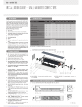
6. Fitting encased convectors on
the wall
• Using the wall brackets
1
mark the
drill holes on the wall. Calculate the spacing
as shown on Diagram 8.
Units longer than 1600 mm require a
further bracket
4
and support plate
5
as a central bracket:
• Fit the brackets using the hexagonal
screws supplied
6
onto the support
plate.
• Position the brackets centrally between
the drill holes for the outer brackets
and mark the drill holes.
• Fix the wall brackets using screws and
rawl plugs (by others)
7
to the wall
and level them.
• Fit the convector by screwing the
brackets
1
using the hexagonal screws
supplied
2
to the support plates
3
of the heat exchanger. If there is a
central bracket (units over 1600mm in
length), fit it in such a way that the heat
exchanger pipes fit into the recesses on
the support plate.
• Connect up the flow
8
and return
9
pipework. The 1/2” valve set type
126102 and the thermostatic valve
head type 110210 from the Kampmann
accessories range can be used. Fit the air
vent
bl
onto the flow connection.
• Place the casing
bm
onto the heat
exchanger with the valve recess aligned
and rotate the fixing plates
bn
(see detail) under the convector.
Diag. 9 Encased convector; casing height 130 mm,
casing depth 180 mm Diag. 10 Section through wall-mounted unit
4
2
2
3
bm
bl
bn
1
6
1
7
8
9
7
7
5
Detail: Rotate fixing
plate
Diag. 8: Bracket spacing - wall-mounted units
*recommended minimum dimensions
*recommended minimum dimension
*
Encased convectors
Encased models with heat exchangers
Installation manual

Valve dimensions
Casing height
mm
Casing depth
mm
Dimensions*
80
130
230
80 180
130
130
180
230
7
1.26
7. P i p e w o r k
* Dimensions based on Kampmann valve set type 126102 (optional accessory); encased convector fitted on a finished floor is illustrated
1 = 1/2” flow
2 = 1/2” return
3 = air vent
4 = 1/2” thermostatic valve body, on flow
5 = thermostatic valve head
6 = 1/2” return shut-off valve
4
2
6
3
1
5
4
2
6
3
1
5
4
2
6
3
1
5
Encased convectors
Encased models with heat exchangers
Installation manual

1.261.26
Pipework dimensions
Casing depth
mm
Casing height 80 mm* Casing height 130 mm*
130
180
230
2
1
2
1
2
1
2
1
2
1
2
1
* Encased convector shown with finished floor brackets
1 = 1/2” flow
2 = 1/2” return
Encased convectors
Encased models with heat exchangers
Installation manual
/