Page is loading ...

INSTALLATION GUIDE – FREE-STANDING CONVECTORS
1. UNIT DESCRIPTION
A free-standing heating unit. Models SUF1, SUF2,
SPF1, SPF2, SMF1, SWF1, SWF2, and SPF0 use the
natural convection heating principle, models SKF1 and
SKF2 are equipped with a fan for forced convection.
Since the heater uses physical laws of thermodynam-
ics it represents one of the most effi cient methods of
interior heating.
Benefi ts of heating convectors:
High output
Silent operation or low noise when the fan is run-
ning (models with a fan)
Lightweight compared to heating units with similar
output which use radiation principle
Low hot water consumption
Short response time
Design
Minimum requirements for operation and mainte-
nance
3. TECHNICAL PARAMETERS
Use: Convectors without fan are designed for dry
and wet environment, and convectors with a fan
are designed for dry environment only.
Maximum operating pressure: 1 MPa.
Maximum operating temperature: 110°C.
Operating medium: Water. It is not allowed to use a
medium other than water. Water may not be mixed
with other substances, such as antifreeze fl uids!
Environment: interiors with temperatures ranging
between +5 °C and +40 °C.
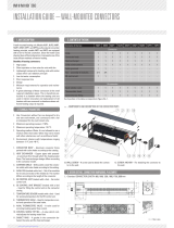
1. CONVECTOR BODY – Aluminum convector frame
painted with color shade according to the catalog.
2. HEAT EXCHANGER – Copper pipes with pressed-
on aluminum fi ns through which the heating water
fl ows. The heat exchanger design differs according
to the convector model.
3. COVERING GRILLE – Grille used to cover the convec-
tor outlet; with color shade according to the catalog.
4. AXIAL FAN (models with a fan) – Set of fan modules
for forced convection of the heated air. The number
differs according to the length of the convector.
5. EB CONTROL UNIT (models with a fan) – Fan motor
control unit.
6. EB CONTROL UNIT BRACKET (models with a fan)
– Used for fi tting the control unit on the convector
casing.
7. TEMPERATURE SENSOR (models with a fan) – Used
for sensing temperature for the EB control unit.
8. THERMOSTATIC HEAD – Used for temperature con-
trol and operation of the axial valve.
9. AXIAL THERMOSTATIC VALVE – A valve used for
incoming heating water fl ow control.
10. CONTROL SCREW FITTING – A valve which controls
/ adjusts the heating water fl ow.
11. GASKET RING – A gasket in the connection be-
tween the valve and the heat exchanger.
12. FLOOR SCREW – A screw used to attach the con-
vector to the fl oor.
13. SCREW ANCHOR – For attaching the convector to
the fl oor.
Contents of the box SKF1 SKF2 SUF1 SUF2 SPF1 SPF2 SMF1 SWF1 SWF2 SPF0
Convector
Grille 1111111111
Convector body 1 1 1 1 1 1 1 1 1 1
Heat exchanger 1 1 1 1 1 1 1 1 1 1
Fan – assembly of modules 2-4 2-4 - - - - - - - -
EB control unit 1 1 - - - - - - - -
Accessories
Axial radiator valve 1 1 1 1 1 1 1 1 1 1
Thermostatic head 1 1 1 1 1 1 1 1 1 1
Control Screw fitting 1 1 1 1 1 1 1 1 1 1
O-ring 18X2 NBR70 2 2 2 2 2 2 2 2 2 2
Valve connection template 1 1 1 1 1 1 1 1 1 1
Screw 6x40 4 4 4 4 4 4 4 4 4 4
Screw anchor 10 4 4 4 4 4 4 4 4 4 4
Flexible hose 41mm - - 1 1 - - - - - 1
Each position in the table corresponds to Figure No. 1.
FIG. 1: COMPONENTS AND DESCRIPTION
OF THE CONVECTOR PARTS
VIEW P:
2. CONTENTS OF THE BOX
4. DESIGN DETAILS, CONNECTION DIMENSIONS, PLACEMENT
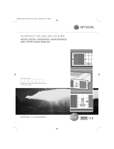
FIG. 2:
L = Standard CONVECTOR LENGTH: 900, 1000, 1250, 1500, 1750, 2000 mm

TABLE 1: applies to all lengths L 900, 1000, 1250, 1500, 1750, 2000 mm
50–150
(by the valves, position 1) and remove it in the direc-
tion of the arrows (position 2) on Fig. 4.
For models with a fan loosen the screws (see the
previous paragraph) in the opposite side wall and
remove it for access to the EB control unit.
Move the strut (y) of grille A to the side and remove
the heat exchanger from the convector casing.
Install the valves (axial valve and the control screw
fi tting) on the heating pipe according to the dimen-
sions on Fig. 2 and Table 1. Adhere to the dimensions
for the particular model.
Fit the convector on the prepared pipes with valves
and fi x it to the fl oor at the fi xing points.
Replace the heat exchanger in the casing and con-
nect it to the installed valves on the heating water
pipes, Fig. 5.
For models SUF1, SUF2, SPF0 – connect the heat ex-
changer with the control screw fi tting using the sup-
plied fl exible hose, Fig. 5a.
For models with a fan - connect the power line to the
EB control unit, Fig. 6.
Place back the side wall(s) and tighten the screws
and install the thermostatic head on the axial valve.
Move back the grille strut(s) and place back the
cover grille.
Vent (bleed) the convector according to section 7 if
necessary.
HEAD OFFICE
MINIB,a.s.
Střešovická 465/49, 162 00 Prague 6
Czech Republic
Tel.: +420 220 180 780, Fax: +420 220 180 779
Email: [email protected], www.minib.com
PRODUCTION
Manufacturing plant of MINIB, a.s.
Býkev u Mělníka 84, 276 01 Býkev
Czech Republic
WWW.MINIB.COM
FIG. 5: Close-up view of the connection between the valves
and the heat exchanger (the heat exchanger design differs
according to the model).
Union nut
Union nut
Supply pipe
Supply cabel
FIG. 6: Close-up view of the power line
connection to the EB control unit.
FIG. 5a: Only for models SUF1, SUF2, SPF0
Please read the following instructions before you start.
Free-standing convectors made by MINIB are to be fl oor-
mounted. We recommend leaving a 50–150 mm space be-
tween the convector and the wall - Figure 3. Never cover
the top grille - this would result in fl ow reduction and a
considerable decrease in the convector output.
Decide whether the convector will act as the main
source of heat, or an additional heating element or, if ap-
plicable, as a thermal barrier.
As the main source of heat in your apartment or room,
the convector should suffi ciently cover the entire ther-
mal loss of the room. Therefore, always choose a heat-
ing unit with a capacity that is higher than the thermal
loss of your apartment, room, or other areas.
All free-standing convectors with a fan are designed
for dry environment. A dry environment is an environ-
ment where the average annual relative humidity does
not exceed 75%. A wet environment is an environment
where such average annual value is equal to or greater
than 75% or where the convector is exposed to direct
contact with water. In terms of convector selection,
a dry environment is in general any environment where
no precipitation of vapor occurs in the convector unit.
5.1 Use the supplied fi xing elements to fi x the free-
standing convector.
A correctly installed convector is in horizontal position
and fi rmly supported along the entire width of the leg.
5.2 Installation process
Plan the placement on the fl oor according to the con-
vector dimensions in table 1 and on Fig. 2.
Use the template for the particular model (Fig. 4)
to mark the heating water supply pipe position, the
power supply position (models with a fan). The outer
dimension of the template = dimension of the leg of
the particular model.
Drill the holes, insert the screw anchors, install the
heating water supply pipe, power supply cable (mod-
els with a fan).
Remove the cover grille. Loosen (do not remove!) the
2 top screws (1) of the right side wall of the convector
5. INSTALLATION
6. CONNECTION OF THE FITTINGS
7. VENTING THE UNIT
FIG. 3: Recommended placement of the free-standing convec-
tor (model with a fan / without fan).
An axial radiator valve is connected to the water inlet
of the heat exchanger. Control screw fi tting is to be
installed on the outlet line. Insert O-rings between the
axial radiator valve / control screw fi tting and the heat
exchanger. Use gaskets for all the other connections.
Vent (bleed) the unit using the air vent valve during the
fi rst use as necessary. In free-standing convectors, the
location of air vent valve on the heat exchanger pipe de-
pends on the model.
For additional options see the catalog or visit:
www.minib.com.
A B C D E F
SKF1 150 248 45 80 120 170
SKF2 150 418 45 80 120 190
SUF1 115 248 30 35 70 145
SUF2 115 418 30 35 70 145
SPF0 150 148 45 30 70 75
SPF1 150 248 45 50 70 115
SPF2 150 418 45 50 195 75
SMF1 195 248 35 85 110 85
SWF1 220 248 45 50 80 145
SWF2 220 418 45 50 80 145
FIG. 4
/