Kampmann 2-stage, 3-phase switch, type 30049 Installation guide
- Type
- Installation guide

Installation instructions
Please keep safe for future use!
Read these instructions carefully prior to starting commissioning!
1.26
1.45
I 106/02/10/1 GB SAP-Nr. 1017344
2-Stage, 3-phase controller 1.96
with room thermostat connection
Type 30049

1. Correct and proper use . . . . . . . . . . . . . . . . . . . . . . . . . . . . . . . . . . . . . . 3
2. Safety information . . . . . . . . . . . . . . . . . . . . . . . . . . . . . . . . . . . . . . . . . . 4
3. Operation . . . . . . . . . . . . . . . . . . . . . . . . . . . . . . . . . . . . . . . . . . . . . . . . . . . 5
4. Electrical connection . . . . . . . . . . . . . . . . . . . . . . . . . . . . . . . . . . . . . . . . . 5
5. Commissioning . . . . . . . . . . . . . . . . . . . . . . . . . . . . . . . . . . . . . . . . . . . . . . 6
6. Technical data . . . . . . . . . . . . . . . . . . . . . . . . . . . . . . . . . . . . . . . . . . . . . . . 7
Printed on environmentally-friendly non-chlorine bleached paper; all rights reserved; our prior permission is required for any reprints even excerpts; we reserve
the right to make changes.
Zeichenerklärung:
Caution! Danger!
The non-observance of
this instruction can lead
to severe damage to
people or property.
Danger of elec-
trocution!
The non-observance of
this instruction can lead
to severe damage to
people or property
through electrocution.
Read these instructions
carefully prior to star-
ting any assembly and
installation work!
All tradepersons involved
in the installation, com-
missioning and operation
of this equipment are
duty-bound to pass this
manual onto any trade-
persons currently or sub-
sequently working on this
equipment, including the
end user. Retain this
manual until final decom-
missioning of the equip-
ment!
Amendments to the
content or style of this
manual can be made
without prior notice!
.1.96 2-Stage, 3-phase controller
with room thermostat connection, Type 30049
Contents

3
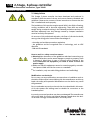
1. Correct and proper use
The Kampmann 2-stage, 3-phase controller Type 30049 has been manu-
factured in accordance with state of the art engineering and recognised
safety directives. However, incorrect installation and commissioning of the
unit or its improper use can cause fatal injury, damage to the unit or dama-
ge to other units or systems.
The Kampmann 2-stage, 3-phase controller Type 30049 should only be
used internally in industrial premises, storage warehouses and office and
retail space. It should not be used outside, in damp areas, in areas where
there is a serious risk of explosion or where there is an aggressive atmos-
phere. The unit must be protected against moisture during installation. If
in doubt, the use must firstly be agreed with the manufacturer. Any other
or exceeding use is deemed as being undesignated. The unit operator is
liable for any resulting damage. Correct and proper use is also deemed to
include compliance with the information on assembly and installation des-
cribed in this manual.
The assembly and installation of this product requires specialist knowledge
of heating, cooling, ventilation and electrical engineering. This knowledge,
generally learned in vocational training, is not described separately. Any
damage caused by inexpert installation must be borne by the operator.
The 2-stage, 3-phase controller Type 30049 can be used with all Kamp-
mann recirculating air unit heaters and roof extract fans which have a 2-
stage, 3-phase motor (Y/Δwindings) with thermal overload contacts for
motor protection::
- TOP, Ultra, TIP, Resistent unit heaters (type numbers ending in 36 or 38)
- Diafort roof extract fans
Scope of this manual
- Electrical installation
- Commissioning and operation
Directives
- Accident prevention directives VBG, VBG4, VBG9a
- DIN VDE 0100, DIN VDE 0105
- EN 60730 (part 1)
- Local electricity company directives and standards (TABs)
and standard engineering practice
Carefully read these instruc-
tions in full prior to installing
the 2-stage, 3-phase controller!
2-Stage, 3-phase controller 1.96
with room thermostat connection, Type 30049
Installation instructions

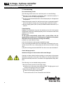
2. Safety Advice
This 2-stage, 3-phase controller has been developed and produced in
accordance with the state of the art and current statutory standards and
guidelines. Observe the contents of these instructions to ensure that the
unit is installed and works properly.
The installation of this product requires special skills in the fields of heating,
cooling, ventilation and in electrical engineering. These skills are usually
taught during vocational training in the indicated professions and are not
described separately here. Any damage caused by inexpert installation
must be borne by the operator.
On account of his professional education, the fitter of this device should,
among other things, also have sufficient knowledge of:
- the safety and accident prevention regulations
- the guidelines and the recognised rules of technology, such as VDE
directives
- DIN and EN standards
How to work in a safety-conscious manner
lWarning! Non-observance of the guidelines and these instructions may
lead to malfunctions and to severe damage to people or property. There
is danger of lethal injury in case of incorrect wiring (change of the
wires)! Disconnect all equipment you need to work on from the
power supply.
lMake sure that this equipment cannot be turned on again by unautho-
rised persons! Wait until the fan comes to a standstill!
lFor installation, only use stable lifting platforms and scaffolding!
Modifications on the device
Do not carry out any modifications, reconstructions or installation work on
the device without prior harmonisation with the manufacturer as this may
impair the safety and operation! Modifications on the device may cancel
the guarantee!
Do not undertake any work on the unit that is not described in this manu-
al. On-site systems and cabling must be suitable for connection to the
intended system!
Incorrectly connected products may become damaged! The manufacturer
will not be liable for injuries and material damage caused when the devi-
ce has been wrongly connected and/or incorrectly used!
4
.1.96 2-Stage, 3-phase controller
with room thermostat connection, Type 30049
Installation instructions

5
3. Operation
The signal lamp
1
signals operational readiness (standby).
lSelect the required speed via the speed selection switch
2
„0-1-2”.
In case of a motor fault the operational readiness light goes out. The
system is switched off and locked.
lTo unlock after a malfunction, position the speed selection switch to „0“.
Attention! After a supply voltage failure the system will restart automati-
cally!
4. Electrical connection
More than one heater can be controlled by one 2-stage, 3-phase control-
ler. Several motors with the same winding type, even with different motor
performance, can be connected to one controller. The number of connec-
ted motors, however, must not exceed the switching capacity of the 2-
stage, 3-phase controller (see page 7, technical data).
The maximum number of units to be connected can be found in the tech-
nical catalogues. If several units are connected to one stage switch, inter-
mediate terminal boxes may be required.
Attention! If switched in groups, all motor windings must always be con-
trolled in parallel and all thermal contacts must be switched in series!
Fuses:
lA 3-pole, 400 V fuse is to be provided on site.
Connecting cables:
lThe cross sections of the control and motor cables should be selected
according to the cable length and power load, but should be at least 1.5
mm².
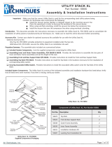
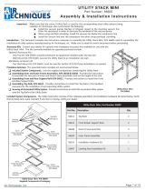
Fig. 1: 2-Stage, 3-phase controller
Type 30049
2-Stage, 3-phase controller 1.96
with room thermostat connection, Type 30049
Installation instructions
1
2
Connecting terminals:
Terminal Potential Function, connection
NZero conductor Feed, external time switch etc.
L1, L2, L3 3x 400 V Feed
U1 - W2 400 V Windings of the fan motor(s)
TK, TK 230 V control voltage Connection of thermal contacts of the fan motor(s)
RT, RT 230 V control voltage Connection of room thermostat, if not available, place a
wire jumper
PE Potential earthing

6
.1.96 2-Stage, 3-phase controller
with room thermostat connection, Type 30049
Installation instructions
5. Commissioning
Pre-commissioning checks:
The following checks have to be carried out prior to commissioning:
lHave all of the equipment components been connected properly in
accordance with the valid wiring diagrams?
lHas the protective earth (PE) been connected properly for all equipment
components?
lHave all thermal contacts for the fan motors been connected properly?
(all of the thermal contacts for a fan group been switched in series)
lHas the supply power (400 V) been provided between terminals L1, L2
and L3?
Commissioning:
Caution! The equipment may only be started up once all of the system
components have been installed properly and all connections have been
checked for correctness.
l Please note:
As the system automatically restarts after a power failure, the fan
speed selector must be set to '0' before power is applied to the system!
Otherwise the fans would start running immediately
l Switch on control device (if any).
lSet the fan selector switch to the required fan stage.
If the connecting terminals RT/RT are electrically connected by the con-
nected control unit or by a wire jumper, the fan motors will start running
now.
lBy disconnecting the terminals RT/RT the fan motors are switched off.
Checks during operation:
Attention! Danger of electrocution with mortal danger!
Carrying out these checks involves working on some parts of the system
which are connected to the mains. The checks can only be carried out by
qualified technical personnel in accordance with appropriate safety direc-
tives.
The following is to be checked during operation:
- Motor protection function of the stage switch:
l Remove one of the wires from terminal TK/TK. The light goes out, all
motors of the group come to a standstill.
- Restart after power failure in all fan stages:
l Switch off the supply voltage briefly.
l Check the function of the connected control devices.

7
6. Technical data
Technical data
Nominal voltage 3 x 400 V, 50 Hz
Max. rated motor current/rated motor power 10 A/ 4 kW
Control voltage 230 V, 50 Hz
Permissible ambient temperature 50 °C
Protection IP 43
Dimensions WxHxD 127 x 160 x 100 mm
2-Stage, 3-phase controller 1.96
with room thermostat connection, Type 30049
Installation instructions

Kampmann GmbH
Friedrich-Ebert-Str. 128 - 130
49811 Lingen (Ems)
Germany
T +49 591 7108-0
F +49 591 7108-300
Kampmann UK Ltd.
Dial House, Govett Avenue
Shepperton, Middlesex, TW17 8AG
Great Britain
T +44 (0)1932 228592
F +44 (0)1932 228949
Kampmann.de
I 106/02/10/1 GB SAP-Nr. 1017344
-
 1
1
-
 2
2
-
 3
3
-
 4
4
-
 5
5
-
 6
6
-
 7
7
-
 8
8


Kampmann 2-stage, 3-phase switch, type 30049 Installation guide
- Type
- Installation guide
Ask a question and I''ll find the answer in the document
Finding information in a document is now easier with AI
Related papers
-
Kampmann TIP 5000 Installation guide
-
-
-
-
-
-
-
-
-
Other documents
-
FieldServer QuickServer 1XXX Quick start guide
-
SMC Sierra Monitor PS-QS-1x11-0154 Installation guide
-
HTP Mod Bus Adapter Installation guide
-
Vulcan Hart VC-1824 User manual
-
 Air Techniques Utility Stacking Racks Owner's manual
-
 Air Techniques Utility Stacking Racks Owner's manual
-
Sealife Sea Dragon Mini 650 Spot & Flood User manual
-
-
Jet Tech F-22 User manual
-
Jet Tech 737-DP User manual

