Page is loading ...

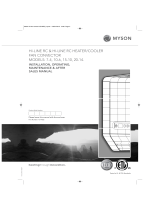
INSTALLATION GUIDE – WALL-MOUNTED CONVECTORS
1. UNIT DESCRIPTION
A wall-mounted heating unit. Models NUF1, NUF2, NMF1,
NWF1, NWF2, NPF1, and NPF2 use the natural convection
heating principle, models NKF1 and NKF2 are equipped
with a fan for forced convection. Since the heater uses
physical laws of thermodynamics it represents one of the
most effi cient methods of interior heating.
Benefi ts of heating convectors:
High output
Silent operation or low noise for units with fan
Lightweight compared to heating units with similar
output which use radiation principle
Low hot water consumption
Short response time
Design
Minimum requirements for operation and mainte-
nance
A great advantage of these convectors is the small
required installation space. This is benefi cial par-
ticularly in a situation where the heating units are
used in interior renovation and replacement of old
heaters with new ones and in situations where suf-
fi cient heating output is required.
3. TECHNICAL PARAMETERS
Use: Convectors without fan are designed for dry
and wet environment, and convectors with a fan
are designed for dry environment only.
Maximum operating pressure: 1 MPa.
Maximum operating temperature: 110 °C.
Operating medium: Water. It is not allowed to use a
medium other than water. Water may not be mixed
with other substances, such as antifreeze fl uids!
Environment: interiors with temperatures ranging
between +5 °C and +40 °C.
1. CONVECTOR BODY – Aluminum convector frame
painted with color shade according to the catalog.
2. HEAT EXCHANGER – Copper pipes with pressed-
-on aluminum fi ns through which the heating water
fl ows. The heat exchanger design differs according
to the convector model.
3. COVERING GRILLE – Grille used to cover the convec-
tor outlet; with color shade according to the catalog.
4. AXIAL FAN (models with a fan) – Set of fan modules
for forced convection of the heated air. The number
differs according to the length of the convector.
5. EB CONTROL UNIT (models with a fan) – Fan motor
control unit.
6. EB CONTROL UNIT BRACKET (models with a fan)
– Used for fi tting the control unit on the convector
casing.
7. TEMPERATURE SENSOR (models with a fan) – Used
for sensing temperature for the EB control unit.
8. THERMOSTATIC HEAD – Used for temperature con-
trol and operation of the axial valve.
9. AXIAL THERMOSTATIC VALVE – A valve used for
incoming heating water fl ow control.
10. CONTROL SCREW FITTING – A valve which cont-
rols/adjusts the heating water fl ow.
11. GASKET RING – A gasket in the connection be-
tween the valve and the heat exchanger.
12. WALL SCREW – A screw used to attach the convec-
tor to the wall.
13. SCREW ANCHOR – For attaching the convector to
the wall.
Each position in the table corresponds to Figure No. 1.
FIG. 1: COMPONENTS AND DESCRIPTION OF THE CONVECTOR PARTS
Contents of the box NKF1 NKF2 NUF1 NUF2 NMF1 NWF1 NWF2 NPF1 NPF2
Convector
Grille 111111111
Convector body 1 1 1 1 1 1 1 1 1
Heat exchanger 1 1 1 1 1 1 1 1 1
Grille reinforcement 1 1 1 1 1 1 1 1 1
Cable grommet 1 1 - - - - - - -
Fan – assembly of modules 2-4 2-4 - - - - - - -
EB control unit 1 1 - - - - - - -
Accessories
Axial radiator valve 1 1 1 1 1 1 1 1 1
Thermostatic head 1 1 1 1 1 1 1 1 1
Control Screw fitting 1 1 1 1 1 1 1 1 1
2. CONTENTS OF THE BOX
4. DESIGN DETAILS, CONNECTION DIMENSIONS, PLACEMENT
FIG. 2: Rear view
L = Standard CONVECTOR LENGTH: 900, 1000, 1250, 1500, 1750, 2000 mm

TABLE 1: applies to all lengths L 900, 1000, 1250, 1500, 1750, 2000 mm
HEAD OFFICE
MINIB,a.s.
Střešovická 465/49
162 00 Prague 6
Czech Republic
Tel.: +420 220 180 809
Fax: +420 220 180 779
Email: [email protected]
www.minib.com
PRODUCTION
Manufacturing plant of MINIB, a.s.
Býkev u Mělníka 84
276 01 Býkev
Czech Republic
WWW.MINIB.COM
FIG. 5: Close-up view of the connection between the valves
and the heat exchanger (the heat exchanger design differs
according to the model)
FIG. 6: Close-up view of the power line connection to the EB
control unit (models with a fan)
Supply
cabel
Union nut
Decide whether the convector will act as the main
source of heat, or an additional heating element or, if
applicable, as a thermal barrier.
As the main source of heat in your apartment or room,
the convector should suffi ciently cover the entire ther-
mal loss of the room. Therefore, always choose a hea-
ting unit with a capacity that is higher than the thermal
loss of your apartment, room, or other areas.
All wall-mounted convectors with a fan are designed
for dry environment. A dry environment is an environ-
ment where the average annual relative humidity does
not exceed 75%. A wet environment is an environment
where such average annual value is equal to or greater
than 75% or where the convector is exposed to direct
contact with water. In terms of convector selection,
a dry environment is in general any environment where
no precipitation of vapor occurs in the convector unit.
Wall-mounted convectors made by MINIB are intended
for installation on the wall below window frames or
sills. Make sure to follow the principle that the distance
from the fl oor should never be less than 110 mm (Figu-
re 3). Never cover the upper grille of the convector –
this would result in fl ow reduction and a considerable
decrease in the convector output.
Use the supplied attachment elements to attach the
wall-mounted convector to the wall.
5.1 Installation process
According to the dimensions in table 1 and on Fig. 2:
–
Measure the holes for attachment of the con-
vector to the wall, drill the holes, insert the
screw anchors, mark, drill the opening for
power supply cable (models with a fan).
– Measure, drill the holes and install the heating
water supply pipe.
– Install the valves on the heating unit according
to section 6. Adhere to the dimensions for the
particular model.
Remove the cover grille from the convector, remove
the casing of convector from the heat exchanger.
Insert the wall screws in the anchors, place the
heat exchanger on them, slightly tighten.
Connect the valves with the heat exchanger (pictu-
red in detail on Fig. 5).
Place the convector casing on the supporting mem-
ber, install the thermostatic head on the axial valve.
For models with a fan connect the power line to the
EB control unit (pictured in detail on Fig. 6).
If necessary, the side walls of the casing can be re-
moved. Loosen (do not remove) the top screws (1)
on Fig. 4 and remove the side wall in the direction of
the arrow (2). Use reverse procedure to place back
the side wall.
Firmly tighten the wall screws. Install the cover grille.
Check and, if necessary, adjust the vertical axle
alignment of the unit with the wall using the ad-
justing screws which are located in the lower part
of the casing.
Vent (bleed) the convector according to section 7.
FIG. 4
5. INSTALLATION 6. CONNECTION OF THE FITTINGS
7. VENTING THE UNIT
FIG. 3: Recommended placement of the wall-mounted convector.
A B C D E F G H I J K
NKF1 150 178 100 130 60 50 85 165 90 145 85
NKF2 150 348 265 130 200 50 85 165 90 315 90
NUF1 115 178 105 130 145 30 60 165 40 145 85
NUF2 115 348 275 130 315 30 60 165 40 190 90
NPF1 150 178 130 50 90 50 85 120 40 145 85
NPF2 150 348 195 50 320 50 85 115 50 315 90
NWF1 220 178 130 50 70 85 155 85 50 145 85
NWF2 220 348 300 50 240 85 155 85 50 190 90
NMF1 195 178 110 85 140 75 140 120 45 145 85
An axial thermostatic valve is connected to the water
inlet of the heat exchanger. Control screw fi tting is to
be installed on the outlet line. Insert O-rings between
the axial thermostatic valve / control screw fi tting and
the heat exchanger. Use gaskets for all the other con-
nections.
Vent (bleed) the unit using the air vent valve during the
fi rst use if necessary. The air vent valve is located on
the heat exchanger pipe.
For additional options see the catalog or visit:
www.minib.com.
/