
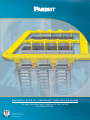
Application Guide For FiberRunner®Cable Routing System
Versatile, Scalable Cable Protection in Data Centers
and Central Offices
Panduit is a Technology
Developer Partner for Storage
Networking Hardware.

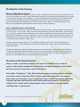
The Need for Cable Routing
What is a Cable Routing System?
A Cable Routing System is a collection of channels, fittings, and mounting brackets that can be assembled to create
a structure that protects fiber optic and high performance copper data cabling from physical damage that can disrupt
or cut off signal transmission. It also provides a versatile, scalable pathway that reduces the costs associated with
maintaining existing network operations and implementing new services. Cable Routing Systems are not just a
means of containing cabling deployed in data centers or central offices. They are an integral component of the
overall cable management system needed to ensure optimum network performance.
Can you afford improper cable routing?
Network problems can cost large companies hundreds of thousands of dollars. A recent study found that companies
can lose as much as 3.6% of their annual revenues to network downtime and service degradation1. Contributing to
this is improperly routed or unprotected fiber optic cable, which is susceptible to various types of damage. Crushing,
pinching, or microbending can result in impeded signal transmission and cable breakage. Bend radius violations, or
macrobending, in fiber optic and copper cables can increase attenuation affecting overall system performance and
cause fatigue leading to long-term signal failure.
Therefore, improperly routed cables are at risk of being damaged and can result in service interruption and
downtime. Identifying, testing, removing, and replacing a damaged cable is costly in terms of labor and network
service interruptions.
A properly designed and installed Cable Routing System carries cabling along a logical route to minimize bends
and optimize cable lengths while providing easy access to make moves, adds, or changes. A well-engineered and
installed Cable Routing System costs a fraction of the potential downtime losses and day-to-day operating costs
over the life of the network, thereby reducing the total cost of ownership.
The Value of the Panduit Solution
Always a leader in providing customers with solutions, Panduit offers a complete
range of cable routing, management, connectivity, and cabling products to meet today’s
data center and service provider central office needs.
The Panduit
®
FiberRunner
®
Cable Routing System ensures maximum network reliability
and reduced cost of ownership. Robust, highly engineered components with integral
bend radius control surfaces can be configured to meet virtually any network application
to provide optimum cable protection and assure network performance. Fast and easy
to deploy, this scalable cable routing solution reduces installation cost and speeds
implementation of new services.
1Infonetics Research, The Cost of Enterprise Downtime, North America 2004.
2

FiberRunner®Cable Routing System Benefits
Ensure network reliability with a complete solution that protects
cables from physical damage while maintaining signal integrity
and delivering reliable network performance.
• Strong, rigid channel and cover profiles protect cables from
impact damage
• Directional fittings provide integral bend radius control and
smooth surfaces, protecting cables from bends and snags
Reduce installation costs with innovative snap-together couplers,
mounting brackets, and accessories that require minimum use
of tools and small fasteners to assemble. These components are
part of a comprehensive system that provides lower installed cost.
• QuikLock™Couplers allow components to be assembled in less
than five seconds without the use of tools
• Covers snap on to channels and fittings, eliminating the need
for tools or small fasteners
• QuikLock™Mounting Brackets allow channel to be attached
to infrastructure without drilling or using small, loose fasteners
Enable future growth or modification with a complete offering
of sizes, fittings, and mounting options that make this system one
of the most versatile cable routing solutions available.
• Wide range of directional fittings allows the system to meet
virtually any network configuration
• Broad assortment of QuikLock™Mounting Brackets allow the
system to be mounted to any type of infrastructure
Lower cost of ownership through a combination of unique
features and standards compliance.
• Snap-on, hinged channel covers and split fitting covers allow
easy access to cables without fully removing covers, thereby
reducing time required to make moves, adds, and changes
• Compliance with stringent industry standards including
UL 2024A and NEBS GR-63 (ensures that system features
and functions will withstand regular use and perform over the
lifetime of the installation)
• Solid, maintenance-free, non-metallic channel and fitting
construction will last the life of the system
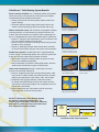
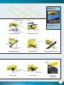
Innovative Snap-On Hinged
Covers attach without use
of tools or small fasteners.
QuikLock™Coupler provides
fast connection between
components without need
for tools or small fasteners.
QuikLock™
Mounting Brackets
speed implementation.
Spill-out fittings provide
bend radius control to
protect cables.
Wide range of directional
fittings provides flexibility.
Panduit ®FiberRunner ®Cable Routing System
dramatically reduces installation time – by
installing up to three times faster than traditional
bolt together systems and up to two times faster
than competitive modular systems.
Bolt
Together
System Competitive
Modular
System FiberRunner ®
System
3
Installation Labor Cost Comparison

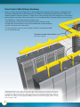
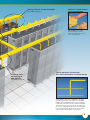
Data Center Cable Pathway Roadmap
Below is a typical data center FiberRunner®Cable Routing System application. The pathway is configured to route
and protect cabling between the Main Distribution Area (MDA) and the Equipment Distribution Areas (EDA)2.Key
features include the innovative QuikLock™Coupler that is used to securely join system components, a wide range of
spill-out options to transition cable into the cabinets, and a complete offering of directional fittings and channel sizes.
Transitions to Other Channel Sizes
(See detail on page 6.)
2MDA, EDA and HDA are terms used in the TIA 942 Telecommunications Infrastructure Standard for Data Centers to
describe primary areas of the Data Center topology. The MDA, or Main Distribution Area, typically has the highest
concentration of cabling. This area usually contains the switches and associated patching field. HDA, or Horizontal
Distribution Area, refers to a smaller version of the MDA, commonly used to minimize long runs of patch cables in
larger data centers. EDA refers to the Equipment Distribution Area that contains all the equipment that is connected
back to the MDA or HDA.
The FiberRunner®Cable Routing System integrates with a
complete offering of Panduit Racks and Cable Management Systems to help
manage higher cable densities as well as StructuredGround™Systems designed
to protect all elements of the data center.
For more information, refer to Pan-Net ®Network Solutions Catalog, SA-NCCB51,
or visit www.panduit.com.
4

Patented QuikLock™Coupler
speeds assembly of system
components without the need for
tools or small fasteners.
QuikLock
™
Coupler Feature
The Distribution and Feeder configuration is the basic,
economic layout used to route cables out of the MDA.
A higher capacity Distribution Run is used to supply the
feeders that route cables out to the cabinets in the EDA.
The Feeders in turn are positioned over the cabinet line
ups to create a pathway that will provide efficient transitions
to the vertical cable management areas of the cabinets
and not interfere with Cold Aisle cooling air flow.
Routing Cables In and Out of the MDA
(See detail on page 6.)
Protecting Cable
Transitioning to
EDA Cabinets
(See detail on page 6.)
Typical Application Configuration:
Plan View of Distribution and Feeder Design
5

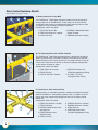
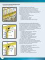
Data Center Roadmap Details
(See Roadmap on pages 4 and 5.)
A. Routing Cable Out of the MDA
The FiberRunner®Cable Routing System includes vertical tee fittings for
routing cables out of the MDA racks. These fittings can be sized for the
anticipated cable capacity and positioned directly above the vertical cable
managers to create as direct a pathway as possible.
Components used in this detail:
1. FRVT12X4 Vertical Tee 4. FRTR6X4 3-Sided Bend Radius
2. FRBC12X4 QuikLock™Coupler Control Trumpet
3. FR12X4 Channel 5. FRBC6X4 QuikLock™ Coupler
B. Transitioning Cables Into the EDA Cabinets
The FiberRunner®Cable Routing System offers a wide variety of spill-out
options to provide safe, accessible transitions to the cabinets in the EDA.
Spill-over fittings, which can be attached to any straight section of channel,
can be used at the initial installation or retrofit into existing configurations
as the network changes or grows.
Components used in this detail:
1. FRSP Spill-Over Junction 4. FIDT2X2 Transition to 1.5''
2. FR6X4 Channel ID Slit Corrugated LoomTubing
3. FBC2X2 QuikLock™ Coupler 5. CLT150F 1.5'' ID Slit
Corrugated Loom Tubing
C. Transitions to Other Channel Sizes
Reducer fittings are available to provide a method of transitioning between
different FiberRunner ®Cable Routing System sizes. In addition, 12x4 tee
fittings and 4-way crosses with integral 6x4 exits can be used to create
feeder runs.
Components used in this detail:
1. FRBC12X4 QuikLock™ Coupler 6. FRBC4X4 QuikLock™ Coupler
2. FR12X4 Channel 7. FRBC6X4 QuikLock™ Coupler
3. FRFWC12X4W6 4-Way Cross 8. FR6X4 Channel
with 6x4 Exits 9. FRRF126R 12x4 to 6x4
4. FRRF6FR4 6x4 to 4x4 Transition Right Reducer Fitting
Reducer Fitting
5. FR4X4 Channel
6
123
4
5
1
2
3
4
5
1
9
7
8
23 4 5
6

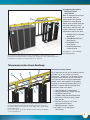
D. Supporting the System
Directly on Racks
and Cabinets
When an overhead infrastructure
is not available, there are
several options that allow the
FiberRunner®Cable Routing
System to be mounted to the tops
of Panduit ®NetFrame ®Racks,
4-Post Racks, EIA/TIA racks, and
Panduit ®Net-Access ™ Cabinets.
Components used in this detail:
1. FEIAB58 EIA/TIA Threaded
Rod Bracket
2. FRRMBNF58 NetFrame®
Rack Bracket
3. FR4PRB58 4-Post
Rack Bracket
4. FR6ACAB Adjustable
Cabinet Bracket
(See pages 12 – 13 for full range
of mounting brackets.)
Telecommunications Rooms
As an alternative to inner duct or exposed cabling
on ladder rack or wire basket tray, the 2x2
FiberRunner®Hinged Duct can be used to route
and protect small amounts of fiber cable along
racks. Vertical Tees with integral hinged doors
provide access and protection. Snap together
transitions to slit corrugated loom tubing and
QuikLock™ Couplers reduce installation time.
Components used in this detail:
1. HC2 FiberRunner ®Hinged Cover
2. HS2X2 FiberRunner®Hinged Channel
3. FVTHD2X2 Vertical Tee
4. FTRBN12 New Threaded Rod Bracket
5. F2PCLB12 2-Piece Clamping Ladder
Rack Bracket
6. FIDT2X2 Transition to 1.5'' ID Slit
Corrugated Loom Tubing
7. FBC2X2 QuikLock™ Coupler
8. CLT150F 1.5'' Slit Corrugated
Loom Tubing
Refer to Pan-Net ®Network Solutions Catalog, SA-NCCB51 or www.panduit.com for more
information about Panduit ®NetFrame ®Rack System, PatchRunner™Vertical Cable Management
Rack System, 4-Post Racks, and Panduit®Net-Access™Cabinets.
Telecommunication Room Roadmap
Panduit offers a complete line of structured cabling products for
Telecommunication Room applications including Rack Systems, Vertical and
Horizontal Cable Management Systems, Grounding and Power Connectors,
Patch Panels, DPoE ™Power Patch Panels, Fiber Optic Cable, and Fiber Optic
Connectivity Products.
For more information, see Pan-Net ®Network Solutions Catalog, SA-NCCB51,
or visit www.panduit.com.
7
2
3
4
1
123
4
5
6
7
8

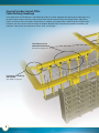
Service Provider Central Office
Cable Pathway Roadmap
In this application, the FiberRunner®Cable Routing System is used to segregate fiber optic jumper cables from all of
the other cables routed in the central office. Key features include innovative Snap-On Hinged Covers, Split Fitting
Covers, and Vertical Tees with integral hinged doors. In addition, the system offers a wide variety of transitions from
horizontal runs to the vertical cable managers on Network Element Bays. These features provide accessibility and
protection, reducing the time required for moves, adds, and changes.
Transitioning to the
Network Element Bays
(See detail on pages 10 – 11.)
Protecting the Pathway
with Covers
(See detail on page 14.)
8

3FDF (Fiber Distribution Frame) refers to the rack or bay lineup that contains the
fiber optic cross-connect. Typically the highest density of fibers are routed from
this location. Network Element Bays refers to the bays that contain the network
equipment that the fiber optic jumper cables are routed to.
Typically used to create a physically redundant pathway
in central offices or high reliability data centers, this
design also provides more routing flexibility and
reduces cable congestion. A larger, higher capacity
channel forms a perimeter around the FDF and
Network Element Bays areas to provide a diverse route
for cables leaving the FDF. Smaller channels are used
to create pathways between the main runs allowing
access to the individual equipment bays.
Typical Application Configuration:
Plan View of Perimeter Design
Mounting to Central
Office Infrastructure
(See detail on pages 12 – 13.)
Transitioning Out of
the FDF Bays3
(See detail on page 10.)
Patented snap-on cover design
speeds installation by eliminating
the need to use tools or
small fasteners.
Snap-On
Hinged Cover Feature
9

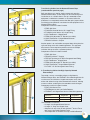
Service Provider Roadmap Details
(See Roadmap on pages 8 and 9.)
A. Transitioning Cable Out of the FDF Bays
For fiber optic jumper cables routed in and out of the Fiber
Distribution Frame, high capacity vertical tee fittings are
positioned directly above the vertical fiber slack managers
providing as direct a pathway as possible. Vertical tee fittings are
typically positioned with doors facing the maintenance aisle to
provide access to the cables.
Components used in this detail:
1. FR12X4 Channel and FRHC12 Cover
2. FRVT12X4 Vertical Tee
3. FRBC12X4 QuikLock™Coupler
4. FRBC6X4 QuikLock™Coupler
5. FRTR6X4 3-Sided Bend Radius Control Trumpet
B. Transitioning Cables into the Network Element Bays
In service provider environments the preference is to completely
enclose the fiber optic jumper cables transitioning from horizontal
runs down to the equipment in the Network Element Bays. There
are several methods that can be used depending upon the
position of the horizontal run relative to the Network Element Bays.
Described below is a component configuration
commonly used:
1. FRVT6X4 or FRVT4X4 QuikLock™Vertical Tee
2. FRLPR42 Low Profile Reducer
3. FOV452X2 Outside Vertical 45° Angle Fitting
4. FIV452X2 Inside Vertical 45° Angle Fitting
5. HC2 FiberRunner ®Hinged Cover
6. FZBA1.5X4 Adjustable “Z” Bracket (not visible)
7. H2X2 FiberRunner ®Hinged Slotted Channel
8. FBC2X2 QuikLock™Coupler
Another option is to use flexible corrugated loom
tubing from the vertical tee fitting to the 2x2 slotted hinged duct.
This approach eliminates the time required to position and secure
multiple individual fittings to create a protected pathway.
Components used in this detail include:
1. FRVT6X4 or FRVT4X4 QuikLock™ Vertical Tee
2. FRLPR42 Low Profile Reducer
3. FIDT2X2 Transition to1.5'' ID Slit Corrugated Loom Tubing
4. HC2 FiberRunner ®Hinged Cover
5. FZBA1.5X4 Adjustable “Z” Bracket
6. H2X2 FiberRunner ®Hinged Slotted Channel
7. FBC2X2 QuikLock™Coupler
8. CLT150F 1.5'' ID Slit Corrugated Loom Tubing
10
1
2
3
4
5
6
7
8
1
2
4
5
6
7
8
12
3
5
4
3

Transitioning Cables into the Network Element Bays
(continued from previous page)
Spill-over fittings can also be used to create exits over the
Network Element Bays. These fittings can be used during initial
installation or as a retrofit when a line-up is extended or new
equipment is added to the network. In the central office the
preference is to completely enclose the fiber optic jumper cables
transitioning from horizontal runs down into the equipment in the
Network Element Bays.
Components used in this detail include:
1. FRSP Spill-Over
2. FOV452X2 Outside Vertical 45° Angle Fitting
3. FIV452X2 Inside Vertical 45° Angle Fitting
4. HC2 FiberRunner ®Hinged Cover
5. FZBA1.5X4 Adjustable “Z” Bracket (not visible)
6. H2X2 FiberRunner ®Hinged Slotted Channel
7. FBC2X2 QuikLock™Coupler
Another option is to use flexible corrugated loom tubing from the
spill-over fitting to the 2x2 slotted hinged duct. This approach
eliminates the time required to position and secure multiple
individual fittings to create a protected pathway.
Components used in this detail include:
1. FRSP Spill-Over
2. FBC2X2 QuikLock™Coupler
3. FIDT2X2 Transition to 1.5'' ID Slit Corrugated LoomTubing
4. HC2 FiberRunner ®Hinged Cover
5. FZBA1.5X4 Adjustable “Z” Bracket (not visible)
6. H2X2 FiberRunner ®Hinged Slotted Channel
7. CLT150F 1.5'' Slit Corrugated Loom Tubing
C. Transitioning Cables into High Capacity Network
Element Bays
To provide a secure, accessible pathway to high density
Network Element Bays, the FRHD4KT 4x4 slotted hinged duct kit
can be used. The innovative, hinged cover opens easily from
either side without having to be removed from the duct, allowing
access to cables, reducing the time needed to make changes.
Components used in this detail include:
1. FRVT12X4 Vertical Tee
2. FRLPR64 6x4 to 4x4 Low Profile Reducer
3. FRHD4KT 4x4 Hinged Duct Vertical Cable Management Kit
The FRHD4KT Kit contains:
• 6' length, 4x4 Hinged Slotted Channel
• 6' length, 4'' Snap-On Hinged Cover
• Adapter to fit exit of 4x4 or 6x4 QuikLock™Vertical Tee or
6x4 to 4x4 Low Profile Reducer Fitting
• Three Adjustable “Z” Brackets, End Cap, and Wire Retainers
Cable Capacity
Comparison
2mm Fiber Optic Cable
1.6mm Fiber Optic Cable
2x2 Slotted
Hinged Duct
349
546
4x4 Slotted
Hinged Duct
1499
2343
11
1
2
4
6
7
3
1
1
3
2
2
4
6
7
5
5
2
3

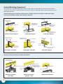
System Mounting Components
The FiberRunner®Cable Routing System provides a wide range of mounting brackets that secure the system to
virtually any data center or service provider infrastructure. QuikLock™Mounting features reduce assembly time and
speed implementation.
Attaching the System to Common Infrastructures Including Auxiliary Framing Bar, Ladder Rack (Cable
Runway), Threaded Rod, Under-Floor Pedestals, and Strut.
5/8" Threaded Rod
FR6TRBN58 QuikLock™New
Threaded Rod Bracket
FRAFC58 Auxiliary
Framing Clip
Auxiliary Framing Support
Attaching the System Directly to Racks and Cabinets.
12
Ladder Rack
Ladder Rack Support
FR6ALB QuikLock™
Adjustable Ladder
Rack Bracket
Ladder Rack Support
F2PCLB58 Two-Piece
Clamping Ladder
Rack Bracket
Top Support ‘C’ Bracket Under-floor Support
Mounting to EIA Racks
Mounting to Panduit
4 Post Rack
Mounting to Panduit®
NetFrame ®Rack
5/8" Threaded Rod
5/8" Threaded Rod
NetFrame ®
Rack
5/8" Threaded Rod
5/8" Threaded Rod
5/8" Threaded Rod
Shown In
Open Position
Shown In
Closed Low
Profile Position
Under-floor
Pedestal
5/8" Threaded Rod
Ladder Rack
FR6TRBN58 QuikLock™
New Threaded Rod Bracket
FR6ACB58 QuikLock ™
Adjustable ‘C’ Bracket
FR6CS58 QuikLock™
Center Support Bracket
FR6TRBN58 QuikLock™
New Threaded Rod Bracket
FRRMBNF58 QuikLock™
NetFrame ®Bracket
FEIAB58 Threaded Rod Mounting Bracket
FR6TRBN58
FR4PRB58 4-Post Rack Bracket
FR6ACB58 QuikLock ™
Adjustable ‘C’ Bracket
FR6USB QuikLock™Under-Floor
Pedestal Bracket
Top Support ‘C’ Bracket

13
Ladder Rack Support
Ladder Rack
Ladder Rack Support
Trapeze Supports Mounting to Strut Systems
Under-Floor Support
Center Support
Center Support Mounting to
Cabinet Tops
FR12TRBE58 QuikLock™
Existing Threaded Rod Bracket
FR6LRB QuikLock™
Ladder Rack Bracket
F2PCLB58 2-Piece
Clamping Ladder Rack Bracket
5/8" Threaded Rod
5/8" Threaded Rod
5/8" Threaded Rod
5/8" Threaded Rod
Cabinet
Strut
Under-Floor
Pedestal
Ladder Rack
FR12TB58 QuikLock™
Trapeze Bracket
FRSTRCLIP QuikLock™
Strut Clips
FR12USB QuikLock™Under-floor
Pedestal Bracket
FR6CS58 QuikLock™
Center Support Bracket
FR12CS58 QuikLock™
Center Support Bracket
FR12ACAB
QuikLock™
Bracket
Innovative QuikLock™
Mounting Slide Clamps allow
fast assembly with a standard
7/16" nut driver.
QuikLock
™
Mounting Feature

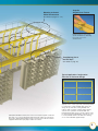
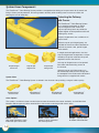
System Cover Components
The FiberRunner®Cable Routing System provides a comprehensive offering of snap-on covers for channels and
fittings. Covers provide protection, enhancing network reliability while enabling ease of access to cables and
lowering the cost of ownership.
Protecting the Pathway
with Covers
The FiberRunner®Cable Routing System
has a complete assortment of unique,
snap-on hinged channel covers and
snap-on split fitting covers to provide the
highest degree of cable protection while still
allowing easy access.
Snap-on hinged covers are available for all
channel sizes.
Optional snap-on split hinged covers are
available for the 4x4 and 6x4 FiberRunner ®
channels to provide a low profile hinged
cover solution.
In height restricted applications, the 12x4
snap-on hinged cover incorporates a unique
secondary hinge that minimizes the space
required to access the channel.
2x2 snap-on hinged cover can be opened
from either side maximizing access to
the channel.
Optional snap-on split fitting covers can
be ordered separately for most fittings with
the exception of the inside vertical directional
fittings which are supplied with covers.
Snap-On Hinged
Solid Cover
12x4 FiberRunner®
Channel Profile
Yellow – Typical
color used to denote a single
mode fiber optic cable route.
Orange – Typically used
to denote multimode fiber.
Black – Used in data
centers in which aesthetics
are more important.
6x4 FiberRunner®
Channel Profile
4x4 FiberRunner®
Channel Profile
2x2 FiberRunner®
Channel Profile
Snap-On Split
Hinged Cover
Snap-On Split
Fitting Covers
System Sizes
The FiberRunner ®Cable Routing System is offered in four channel sizes providing a range of cable capacity.
Color Options
The system is available in three standard colors to meet the need for data center aesthetics and to differentiate
between different types of cables routed within a data center or service provider central office.
14

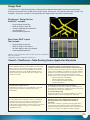
Design Tools
The FiberRunner®Cable Routing System is offered with two different Design Tools that allow accurate system
drawings to be created which speeds overall system design, specification, and implementation. Both a VISIO* and
AutoCAD** version are available as free downloads from: www.panduit.com/products/selectiontools.
Panduit
®
FiberRunner
®
Cable Routing System Application Standards
FiberRunner®Design Tool for
AutoCAD** includes:
• Drag-and-drop functionality
• Ability to design in 2D or 3D
• Versions compatible with AutoCAD**
and AutoCAD** LT
• Automated BOM generator
Data Center VISIO* Layout
Tool includes:
• Drag-and-drop functionality
• Ability to design in 2D (stencils
for three different views are provided)
• Automated BOM generator
NEBS GR-63 CORE, Level 3 Compliance as tested by NTS
Network Equipment Building Systems (NEBS) was developed by
Bellcore, now know as Telcordia Technologies, and is currently
maintained by Telcordia Technologies. NEBS was developed to
standardize requirements for Central Office Equipment and to
develop criteria for personal safety, protection of property, and
operational continuity.
UL Underwriters Laboratories, Inc.
Underwriters Laboratories, Inc. is an independent, not for profit
safety testing and certification organization based in the
United States.
NEBS Level 3 Criteria is the minimum of environmental
compatibility needed to provide maximum assurance of
equipment operability within the network facility environment.
The Level 3 Criteria is the highest assurance of product operability.
Products that meet NEBS Level 3 Criteria are suited for equipment
applications, which demand minimal service interruptions over the
life span of the equipment. The Panduit®FiberRunner ®Cable
Routing System has successfully passed a range of tests including:
• Extreme Temperature and Humidity
• Operating Temperature and Humidity
• Zone 4 Earthquake and Office Vibration
• Needle Flame Analysis
UL 2024A Optical Fiber Cable Routing Assemblies
Covers, fittings and components construction, flammability rating
and marking. The FiberRunner®Cable Routing System has passed
test requirements for Riser Rated applications.
UL V-0 Flammability Rating
Underwriters Laboratories, Inc. Standards applicable to specified
Panduit ®FiberRunner ®Cable Routing System components.
TIA Telecommunications Industry Association
The Telecommunications Industry Association is a leading U.S.
non-profit trade association serving the communications and
information technology industry. TIA represents providers of
communications and information technology products and services
for the global marketplace through its core competencies in
standard development.
ANSI/TIA-942 Draft 5.0a – Telecommunications Infrastructure
Standard for Data Centers ANSI/TIA-569-B Commercial
Building Standard for Telecommunications Pathways
and Spaces
Referenced as a method of separating and routing data cable in
overhead cable routing applications. The Panduit®FiberRunner®
Cable Routing System provides pathway components that allow the
system to be configured in compliance with these standards.
15
*VISIO is a registered trademark of Microsoft Corporation in the United States
and/or other countries.
**AutoCAD is a registered trademark of Autodesk, Inc.

For a copy of Panduit product warranties, log on to www.panduit.com/warranty
© 2011 Panduit Corp.
ALL RIGHTS RESERVED
Printed in the U.S.A.
Brochure Number SA-FRCB02
7/2011
WORLDWIDE MANUFACTURING LOCATIONS
Orland Park,
Illinois, USA
Panduit Corp.
Worldwide Headquarters
Tinley Park, Illinois 60487
For more information
Visit us at www.panduit.com
Contact Customer Service by email: [email protected]
or by phone: 800-777-3300
Lockport,
Illinois, USA
Burr Ridge,
Illinois, USA
Monterrey Nuevo Leon,
Mexico
Cumming,
Georgia, USA
Romeoville,
Illinois, USA
Grecia, Alajuela
Costa Rica
Singapore Wuxi,
China
-
 1
1
-
 2
2
-
 3
3
-
 4
4
-
 5
5
-
 6
6
-
 7
7
-
 8
8
-
 9
9
-
 10
10
-
 11
11
-
 12
12
-
 13
13
-
 14
14
-
 15
15
-
 16
16


Ask a question and I''ll find the answer in the document
Finding information in a document is now easier with AI
Related papers
-
Panduit FTR4X4BL Datasheet
-
-
Panduit FRBC6X4YL Installation guide
-
-
Panduit FRBC12X4YL Installation guide
-
Panduit PN616C User manual
-
Panduit Z22U User manual
-
Panduit LDPH3 User manual
-
-
Other documents
-
EZ-ACCESS Pathway Operating instructions
-
 John Deere RT 2283 User manual
-
 John Deere RT 1157 User manual
-
 John Deere RT1240 User manual
-
 TE Connectivity 6417 2 055-01 Datasheet
-
 John Deere SB1107 User manual
-
Alcatel-Lucent 7450 ESS-7 Installation guide
-
 TE Connectivity 1374463-4 Datasheet
-
-


