LINK-MI LM-TVM46 User manual
- Category
- TVs & monitors
- Type
- User manual
This manual is also suitable for

1
4x4 Seamless Switch 4K HDMI Matrix &
Video Wall Controller

2
Operating Instruction
Thank you for purchasing this product. For optimum performance and safety, please read
these instructions carefully before connecting, operating or adjusting this product. Please
keep this manual for future reference.
SAFETY PRECAUTIONS
Please read all instructions before attempting to unpack, install or operate this equipment
and before connecting the power supply.
Please keep the following in mind as you unpack and install this equipment:
Always follow basic safety precautions to reduce the risk of fire, electrical
shock and injury to persons.
To prevent fire or shock hazard, do not expose the unit to rain, moisture or
install this product near water.
Never spill liquid of any kind on or into this product.
Never push an object of any kind into this product through any openings or
empty slots in the unit, as you may damage parts inside the unit.
Do not attach the power supply cabling to building surfaces.
Use only the supplied power supply unit (PSU). Do not use the PSU if it is
damaged.
Do not allow anything to rest on the power cabling or allow any weight to be
placed upon it or any person walk on it.
To protect the unit from overheating, do not block any vents or openings in the
unit housing that provide ventilation and allow for sufficient space for air to
circulate around the unit.

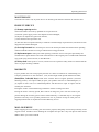
3
Operating Instruction
CONTENTS
1. DEAR CUSTOMER·······················································4
2. FEATURES··································································4
3. NOTICE······································································4
4. SPECIFICATIONS························································5
5. PACKAGE CONTENTS················································· 5
6. OPERATION CONTROLS AND FUNCTIONS····················6
6.1 Front Panel ··········································································· 6
6.2 Rear Panel············································································· 6
6.3 Remote Control Description························································ 7
7. CONNECTINGAND OPERATING···································7
8. PANEL CONTROL························································8
8.1 Video switch operation·······························································8
8.2 Video control·········································································· 8
8.2.1 Video······························································································9
8.2.2 Mode···························································································· 18
8.2.3 Audio Settings interface······································································25
8.2.4 EDID Settings················································································· 27
8.2.5 Preset Settings················································································· 27
8.2.6 Setup interface················································································· 28
8.2.7 Query information interface································································· 31
9. CONNECTION DIAGRAM··········································· 32
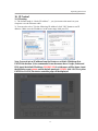
10. IP CONTROL····························································33
10.1 IP setting············································································ 33
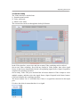
10.2 Switch setting······································································ 34
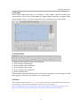
10.3 Format···············································································35
10.4 Video Offset········································································ 35
10.5 Store················································································· 35
10.6 Modify Port Name·································································36
10.7 Audio················································································ 37
10.8 EDID setting······································································· 37
11. NETWORK INTERFACE DESCRIPTION······················ 38
12. SYSTEM INTERFACE DESCRIPTION··························39
13. THE FIRMWARE UPDATE········································· 40
13.1 MCU application layer upgrade················································· 40
13.2 CPLD················································································40
13.3 GUI Application layer upgrade·················································· 41
13.4 GUI web page upgrade··························································· 41
MAINTENANCE····························································42
PRODUCT SERVICE······················································42
WARRANTY································································· 42

4
Operating Instruction
1. Dear Customer
Thank you for purchasing this product. For optimum performance and safety, please read
these instructions carefully before connecting, operating or adjusting this product. Please
keep this manual for future reference.
The Matrix offers solutions for digital entertainment center, HDTV retail and show site,
HDTV, STB, DVD and projector factory, noise, space and security concerns, data center
control, information distribution, conference room presentation, school and corporate
training environments.
2. Features
Any one of the 4 sources to any one of the 4 displays.
Seamless switching ensures no switching delay and pictures loss during transitions,
the switching speed is less than 40 millisecond.
Support video wall mode and output image mirror function
Any one of the four outputs can be turned off independently.
Support PCM 2CH audio.
Support EDID management
Compliant HDCP 2.2 and HDCP1.4
Support high definition resolutions, including: 4K30HZ,1080p@60Hz@36 b/pixels,
and other standard video formats.
Support output downscale to 1080P/720P/2560*1440/1920*1200/1360*768
With panel button, Remote Control, RS232 Control, TCP/IP Control to select the
source.And support for third-party platform control.
1U rack design ,easy installment.
DC 12V 2A power supply.
Unit size:L438*W205*H44mm.
3. NOTICE
Our company reserves the right to make changes in the hardware, packaging and any
accompanying documentation without prior written notice.

5
Operating Instruction
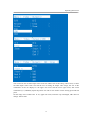
4. SPECIFACATIONS
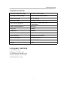
5. PACKING CONTENTS
1). 4x4 Matrix x1pcs
2). Remote Controller x1pcs
3). CD ROM (user manual) x1pcs
4). Power Adapter 12V2A x1pcs
5). Mounting Ears x1pair
Operating Temperature Range 0 to +40°C (32 to +104°F)
Operating Humidity Range 5 to 90 % RH (no condensation)
Input Video Signal 0.5-1.0 volts p-p
Input DDC Signal 5 volts p-p (TTL)
Video Format Supported DTV/HDTV: 1080P/1080i/720P/
576P/480P/4K
Audio Format Supported LPCM 2.0
Input ports 4xHDMI
Output ports 4xHDMI
Matrix mode 4x4 Seamless switching
Video wall mode Multiple video wall modes
Power consumption 20watts(Maximum)
Dimension (mm) L438XW205XH44 mm
Weight 2710g

6
Operating Instruction
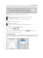
6. OPERATION CONTROLS AND FUNCTIONS
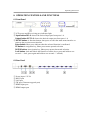
6.1 Front Panel
①LCD screen and IR receiving port, indicator light
②Input button IN1~4: choose the desired input port from ports 1~4
Output button OUT1~4: choose the desired output port from ports 1~4
③MENU button: A function button, short press to enter the main menu interface or
return to the previous menu interface
Enter button: Short press indicates that the selected function is confirmed
UP button:A navigation key, Short press means upward selection
DOWN button: A navigation key, Short press means downward selection
Lock button: lock and unlock the function of all the keys (press and hold on one
second------lock, press again and hold on one second------unlock)
6.2 Rear Panel
①Power input: 12V2A
②RS232 port
③LAN port
④FW port (Firmware upgrade port)
⑤HDMI input port
⑥HDMI output port

7
Operating Instruction
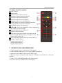
6. 3 Remote Control Description
1Power on/off
2Mute button
3previous source and next source
4Enter the seamless matrix mode(red)
5Enter the video wall mode(green)
6Enter the multi-viewer mode(blue)
7Enter the mirror viewer mode(yellow)
8MENU button: to enter the main menu interface
or return to the previous menu interface
9All button: choose all Output port.
10 ▲▼◄ ►: Moves the highlight to select a displayed.
OK: Enters the selected item.
11 Display and mask the OSD menu
12 Same as the menu button
13 Select the input sources under video matrix mode,
such as:Output 1 display input 1, or Output 1,2,3,4
display input 1 and so on.
14 The menu button that the scenario recalls and save
15 Output 1 display input 1,
Output 2 display input 2,
Output 3 display input 3,
Output 4 display input 4.
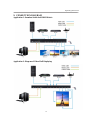
7. CONNECTINGAND OPERATING
1. Connect source devices to input ports of the matrix
2. Connect HDMI output port to TV or other HDMI sink devices.
3. Optional: connect RS232 cable from PC RS232 port .
4. Optional: connect an Ethernet cable from the TCP/IP port on the matrix to a local area
network.
5. Connect 12V/2A POWER supply to DC power socket.
6. Power on the matrix ,HDMI sources and displays.

8
Operating Instruction
8. Panel control
8.1 Video switch operation
Signal switching includes 4 switching channels, which can be randomly configured as input/output
according to requirements to form a matrix of 1×4~4×1. It can switch any input signal to 1 channel of
output or all channels of output.
Operation format: "output channel" + "input channel"
Such as:
1. Switch output 1 to input 2 source
Operation: press "1" in Output area + "2"in IN area to complete the switch
2. Output 1,2,4 switch to input 3 source
Operation: press "1", "3" and "4" in Output area + "2" in IN source area to complete the switch
3. Switch all output port to input 4 source
Operation: press anynumberinOutputarea+"4"inINareatocompletetheswitch
4. Go directly into the video wall mode of input 2 signal source
Operation: press the number "2" in the Input area to complete the switch
8.2 Video control
There are five submenus in the Video interface:

9
Operating Instruction
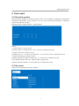
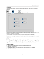
8.2.1 Video
1). Video switch
Operation:
1In the main menu, select "Video" to press the "OK".
2press “ up and down” button to select "Output1" (The fifth ALL option means that all outputs
are selected)
3click on "OK" to enter the next submenu
4Press the“ up and down” button to select "Swtching" to select the input signal source.The
bottom color of the selected input is white
5click "OK" to enter the next submenu
6Press the ”up and down” button to select the "Input" , and the color at the bottom of the selected
input port becomes white
7click on the "OK" button to complete switching
You can switch any output to any input, or all output to the same input.
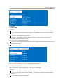
2). Output switch control
You can open/close any of the output port, or open/close all output port.
Operation:
1in the main menu, select "Video" to press the "OK"
2press “ up and down” button to select "Output1" (The fifth ALL option means that all outputs
are selected)
3Click "OK" to enter the next submenu

10
Operating Instruction
4Press the “up and down” button to select the "On/Off"
5Click "OK" to enter the next submenu
6Press “up and down” button to select Off or On.
7Press the "OK" button to confirm that the output port is open/ closed.
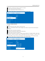
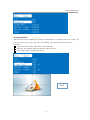
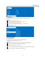
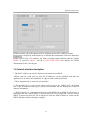
3). Output resolution selection
Operation:
1In the main menu, select "Video" to press the "OK"
2Press “ up and down” button to select "Output1" (The fifth ALL option means that all outputs
are selected)
3Click "OK" to enter the next submenu
4press the “up and down” button to select "Resolution"
5Click "OK" to enter the next submenu
6Press the”up and down” bottom to complete selection (There are 6 output resolution : 4K 30 Hz,
1080P 60 Hz, 720P 60 Hz,2560 X1440, 1920X1200,1360 X768 and AUTO, as shown in the
picture.the default is Auto,)The color of the bottom of the selected output resolution become white.
7Click the "OK" button to complete the output video resolution setting

11
Operating Instruction
You can choose any one of the output video resolution, or choose all of the output video resolution,
the system default use Auto (this option is the product according to the displays judgment).
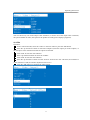
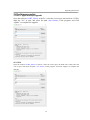
4). OffSet
Operation:
1In the video wall mode, select the "Video" in the main menu to press the "OK"button.
2Press the “up and down” button to select the "Output1"(select the output you want to adjust ) or
the 5th option "ALL"which means that all outputs are selected.
3Click "OK" to enter the next submenu.
4Press“upanddown”buttontoselectthe"OffSet"
5Click "OK" to enter the next submenu.
6Press the “up and down” button to select X and Y. X and Y have 301 sub-items, the minimum is
0, the maximum is 600, the number adjustment interval is 2.
7Click the "OK" button to complete the offset setting.

12
Operating Instruction
You can select the offset(The margin of the display screen) of any one of the output video, or select
the offset for all of the output video screens. (Offset apply to video wall mode).
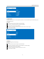
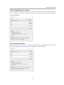
5). Rotate
Operation:
1In the main menu, select "Video" to press the "OK"
2Press “ up and down” button to select "Output1" (The fifth ALL option means that all outputs
are selected)
3Click "OK" to enter the next submenu.
4Press the “up and down”to select the "Rotate"
5Click "OK" to enter the next submenu.
6Press the “up and down” button to select the "Yes" to open or the "No" is closed
7Click the "OK" button to complete the setting.
You can select any key to select output1 rotations or all the output rotations. The rotation is 180°
clockwise
6). Color
Operation:
1In the main menu, select "Video" to press the "OK"
2Press “ up and down” button to select "Output1" (The fifth ALL option means that all outputs
are selected)
3Click "OK" to enter the next submenu.
4Press the “up and down” button to select the "color"
5Click "OK" to enter the next submenu.
6Press the “up and down” button to select the "Yes" to open or the "No" is closed
7Click the "OK" button to complete the color setting.

13
Operating Instruction
You can choose any output(such as output1)’s color Settings or select all output the picture color
Settings, you can set the contrast, brightness, saturation, color, and R, G, B offset, etc.You also can
choose the “Reset” to restore all the default Settings.Each option can be set 0-100 (the system default
parameters for 50), the color of the above parameters can be set according to your own preferences.
7). Top
Operation:
1In the main menu, select "Video" to press the "OK" .
2Press “ up and down” button to select "Output1" (The fifth ALL option means that all outputs
are selected)
3Click "OK" to enter the next submenu.
4Press the “up and down”button to select the "Top" .

14
Operating Instruction
5Click "OK" to enter the next submenu.
6Press the “up and down” button to select the "CH0" to close or the "CH1" is open
7Click the "OK" button to complete the setting.
You can choose the Top area (one of the output port’s) to display CH0 or CH1.
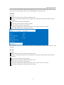
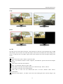
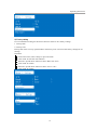
8). CHO
Operation steps:
1In the main menu, select "Video" to press the "OK" .
2Press “ up and down” button to select "Output1" (The fifth ALL option means that all outputs
are selected)
3Click "OK" to enter the next submenu.
4press the “up and down” button to select "CH0"
5Click "OK" to enter the next submenu and there are two submenus of CH0: Crop,Zoom
6Press the “up and down” button to select “Crop” to set Start x : 0, Start y : 0, End x :6000, End
y: 6000 (There are 61 subitems under each coordinate, minimum 0, maximum 6000, each value
interval 100, the defaults value of selected video:( the upper left corner Start (0, 0), the lower right
corner End (6000, 6000), midpoint (3000, 3000))
7Click on the "OK"button to complete the setting.
8Press the “up and down” button to select “Zoom” . There are four subitems under Zoom: Start x:
0, start y :0, End x:3000, End y:3000;
9click on the "OK" button to complete the setting.

15
Operating Instruction
You can choose one of CH0 output video screen size and the size of the cutting video screen, or select
all CH0 output video screen size and the size of cutting all output video image, the size of the
coordinates of the out displays in the upper left corner and the lower right corner, full screen
coordinates (0, 0, 6000600), adjust the picture size and cut size need to set the starting point and end
point.
Set the image size of CH0’s OU1 as 4/1, upper left corner, when the crop unchanged, CH1 does not
change. TOP is CH0.

16
Operating Instruction
Corp:
Zoom:
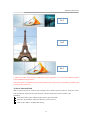
9). CH1
CH1 has one more select Source function. Crop and Zoom are the same as the operation steps of CH0
main channel. You can select one of the CH1 output video screen size and the size of the cutting video
screen, or select the size of all CH1 output video screen and the size of the all output cutting video
screen.
Operation:
1In the main menu, select "Video" to press the "OK" .
2Press “ up and down” button to select "Output1" (The fifth ALL option means that all outputs
are selected)
3Click "OK" to enter the next submenu.
4Press “ up and down” button to select ”CH1”
5Click "OK" to enter the next submenu.There are 3 submenu:Crop、Zoom、Source.
6Crop, Zoom is the same as the CH0 operation.
7Click "OK" to enter the next submenu,and there are three subitems under Source:
Matrix,Next,Mute
8When we click "Matrix" , the CH1 is the same as the CH0 signal source, and the image is the
same.

17
Operating Instruction
9When we click "Next", then the signal source of CH1 is the next signal source, and the output
screen is the image of the next signal source.
10 When we click "Mute", then close the CH1 image,.After we select “Mute” ,the CH1 screen is
black screen.
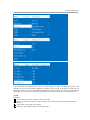
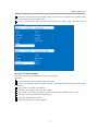
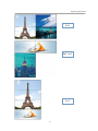
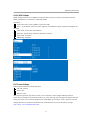
10). CH0, CH1 mirror Settings
You can set CH0 or CH1 to mirror the X-axis or Y-axis image.
Operation:
1In the main menu, select "Video" to press the "OK".
2Press “ up and down” button to select "Output1" (The fifth ALL option means that all outputs
are selected)
3Click "OK" to enter the next submenu.
4Press the” up and down” button to select "CH0".
5Click "OK" to enter the next submenu, press the “up and down” button to select “Crop”
6Set Start x:0, Start y:6000, End x:6000, End y:0
7Click the "OK" button to confirm
8Horizontal mirror screen setup complete

18
Operating Instruction
Vertical mirror diagram
Horizontal mirror diagram
8.2.2 Mode
The Mode control interface has 4 submenus:
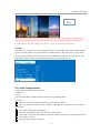
1). Seamless matrix Mode
Seamless is the interface of Seamless switch of matrix, Seamless can seamlessly switch all input
signal sources, can choose 1~4 signal sources, or choose P2P (one signal source to one screen)
Operation:
1In the main menu, select "Mode" to press the "OK" .
2Press the “up and down” button to select "Seamless"
3Click "OK" to enter the next submenu.
4Press the “up and down” button to select the "Input" (the first option is P2P mode)
5Click "OK" to complete the switch.

19
Operating Instruction
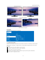
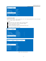
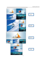
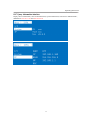
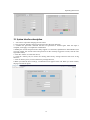
2). Video-wall Mode
Video-wall can select 4 display sets to make a picture.There are 10 preset scenes (2x2, 1x2x2, 1x2,
2x1x2, 2x1, 2x1 1x2, 1x3, 3x1, 1x4, 4x1). After clicking, you can select the scene you need.
Operation:
1In the main menu, select "Video-wall" to press the "OK"
2Press the” up and down” button to select the scene you want
3Click on the "OK" to complete the setting
2x2

20
Operating Instruction
2x1x2
2x1
1x2x2
Page is loading ...
Page is loading ...
Page is loading ...
Page is loading ...
Page is loading ...
Page is loading ...
Page is loading ...
Page is loading ...
Page is loading ...
Page is loading ...
Page is loading ...
Page is loading ...
Page is loading ...
Page is loading ...
Page is loading ...
Page is loading ...
Page is loading ...
Page is loading ...
Page is loading ...
Page is loading ...
Page is loading ...
Page is loading ...
Page is loading ...
-
 1
1
-
 2
2
-
 3
3
-
 4
4
-
 5
5
-
 6
6
-
 7
7
-
 8
8
-
 9
9
-
 10
10
-
 11
11
-
 12
12
-
 13
13
-
 14
14
-
 15
15
-
 16
16
-
 17
17
-
 18
18
-
 19
19
-
 20
20
-
 21
21
-
 22
22
-
 23
23
-
 24
24
-
 25
25
-
 26
26
-
 27
27
-
 28
28
-
 29
29
-
 30
30
-
 31
31
-
 32
32
-
 33
33
-
 34
34
-
 35
35
-
 36
36
-
 37
37
-
 38
38
-
 39
39
-
 40
40
-
 41
41
-
 42
42
-
 43
43


LINK-MI LM-TVM46 User manual
- Category
- TVs & monitors
- Type
- User manual
- This manual is also suitable for
Ask a question and I''ll find the answer in the document
Finding information in a document is now easier with AI


Other documents
-
DirekTronik SX-VW02 User manual
-
 Foxun SX-MVS02 User manual
-
 SECOMP 14.01.3569 Installation guide
-
-
-
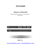 infobit iMatrix H44VAW User manual
-
Canon XF200 Owner's manual
-
-
Extron SMD 202 User manual
-


