Page is loading ...


Mariner 320
Instruction Manual Breathing Air Compressors
i
INTRODUCTION
This manual contains operating instructions and mainte
nance schedules for the high pressure breathing air compres
sors
WARNING
! Pneumatic high pressure system !
The breathing air produced with the compressor units de
scribed in this manual is subject to strict quality standards.
Ignoring the operating and maintenance instructions can
lead to severe injury or death.
This compressor has been built in accordance with the EC ma
chine regulations 2006/42/EG. Specifications on the noise
level in accordance with the machine and product safety law
as of 01.05.2004 and the EC machine regulations, chapt. I,
section 1.7.4. The machine has been built according to the
highest standard of technology and the generally acknowl
edged safety standards. Nevertheless, operation could still
cause danger for the operating personnel or third parties, or
result in damage to the machine and other values. The ma
chine may only be used to produce compressed air as speci
fied in this manual. Other use is strictly prohibited.
Edition January 2010
© 2010 BAUER Kompressoren GmbH, München
All rights reserved.

Instruction Manual Breathing Air Compressors
ii
TABLE OF CONTENTS
1. GENERAL 1. . . . . . . . . . . . . . . . . . . . . . . . . . . . . . . . . . . . . . . . . . . . . . . . . . . . . . . . . . . . . . . . . . . . . . . . . . . . . . . . . . . . . .
2. SAFETY MEASURES 11. . . . . . . . . . . . . . . . . . . . . . . . . . . . . . . . . . . . . . . . . . . . . . . . . . . . . . . . . . . . . . . . . . . . . . . . . . . . . .
3. INSTALLATION, OPERATION, FILLING PROCEDURE 16. . . . . . . . . . . . . . . . . . . . . . . . . . . . . . . . . . . . . . . . . . . . . . . . . . . . .
4. MAINTENANCE 25. . . . . . . . . . . . . . . . . . . . . . . . . . . . . . . . . . . . . . . . . . . . . . . . . . . . . . . . . . . . . . . . . . . . . . . . . . . . . . . . .
5. STORAGE, PRESERVATION 50. . . . . . . . . . . . . . . . . . . . . . . . . . . . . . . . . . . . . . . . . . . . . . . . . . . . . . . . . . . . . . . . . . . . . . . .
6. REPAIR INSTRUCTIONS 51. . . . . . . . . . . . . . . . . . . . . . . . . . . . . . . . . . . . . . . . . . . . . . . . . . . . . . . . . . . . . . . . . . . . . . . . . . .
7. TABLES 52. . . . . . . . . . . . . . . . . . . . . . . . . . . . . . . . . . . . . . . . . . . . . . . . . . . . . . . . . . . . . . . . . . . . . . . . . . . . . . . . . . . . . . . .
8. ANNEX 55. . . . . . . . . . . . . . . . . . . . . . . . . . . . . . . . . . . . . . . . . . . . . . . . . . . . . . . . . . . . . . . . . . . . . . . . . . . . . . . . . . . . . . . .
INDEX
A
Adhesive chart, 53
Air flow diagram, 7
Ambient temperature, 34
B
B-Timer, 21
C
Change-over device, 19
Changing the oil type, 26
Compressor block, 6
Condensate drain, 35
timer adjustment, 45
Cooling system, 47
Cycle counter, 45
D
Drive system, 47
E
Electrical system, 44
Emergency shutdown, 45
F
Filling procedure, 18
Filter system, 28, 34
Final separator, 34
Fuse table, 16
I
Installation, 16
Intake air quality, 18
Intake filter, 28
Intermediate separator, 28
L
Lubrication, 25
Lubrication chart, 53
M
Maintenance instructions, 25
Maintenance kits, 52
Maintenance parts, 52
Maintenance record, 25
Maintenance schedule, 25
O
Oil change, 26
Oil pressure switch, 45
Oil pump, Venting, 27
Operation, 17
P
Preservation, 50
Pressure gauge, 40
Pressure switch, 44
Pressure-maintaining valve, 39
S
Safety valves, 39
Sealant chart, 53
Service switch, 45
Shut-down, 20
Starting the unit, 17
Storage, 50
T
Tables, 52
Technical data, 8, 9, 10
Testing agents, 53
Tightening torque values, 53
Torque sequence, 53
V
Valves, 40

Instruction Manual Breathing Air Compressors
iii
ANNEX
Air flow diagram 80721
Pneumatic parts list 76360
Schematic diagram for unit with motor protection switch 76942-S01
Schematic diagram for unit with compressor control system 80228
Schematic diagram for unit with Honda engine and automatic condensate drain 80862
Electric parts list 76360
Operating instructions for automatic condensate drain timer ---
Lubricating oil list 70851
Applicable parts list
Mariner 320 TM320-4/3
Mariner 320 420 bar TM320-420-4/3
Dear customer
We are happy to give you advice on any questions regarding your BAUER compressor and help as soon as possible with any
arising problems.
You can contact us Mondays to Thursdays from 08
00
till 16
30
, Fridays from 08
00
till 14
00
on phone no. (089) 78049-0.
If you call the following extensions directly, it will save you time and repeated dialling.
Do you want to order spare parts?
Customer service Phone no: (089) 78049-129 or -149
Fax no: (089) 78049-101
Do you have problems with maintenance or repair work?
Technical customer service Phone no: (089) 78049-246 or -176
Fax no: (089) 78049-101
Do you need further information regarding your unit, accessories, prices etc.?
Sales department Phone no: (089) 78049-138, -185, -154, -205 or -202
Fax no: (089) 78049-103
Are you interested in any training courses?
Training manager Phone no: (089) 78049-175
Fax no: (089) 78049-101
Meet us in the internet at: www.bauer-kompressoren.de

Instruction Manual Breathing Air Compressors
iv
NOTES
Model:
Serial no.:
Date of purchase:
Dealer address/phone no.:

Instruction Manual Breathing Air Compressors
1
1. GENERAL
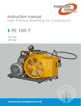
PURPOSE AND SHORT DESCRIPTION
The Mariner 320 high pressure compressors are designed to
compress air for breathing as required in diving and fire fight
ing applications. The max. allowable operating pressure (ad
justed pressure on final pressure safety valve) is 225 bar or
330 bar depending on unit.
DESIGN AND MODE OF OPERATION
Design
The compressor unit comprises the following major assem
blies:
• compressor block
• drive motor
• filter assembly
• filling assembly
• protection and anti-vibration frame
• automatic condensate drain
a)
• electric control system
a)
The compressor units are available with electric motor or pet
rol engine drive (Abb. 1 to Abb. 8).
Abb. 1 Compressor unit Mariner 320
a) optional extra according to order

Instruction Manual Breathing Air Compressors
2
1 Motor intake filter
2 Motor exhaust
3 Fuel tank
4 Filling valve
5 Oil filler neck
6 Compressor block
7 Compressor intake filter
8 Final pressure safety
valve
8 Safety valve
9 Rope starter
10 Hinged motor plate
11 Condensate drain tap
12 Filling manifold
13 Pressure maintaining/
non-return valve
14 Filter system P31
13
10
6
13
25
9
7
12
8
11 14
4
Abb. 2 Compressor unit with petrol engine on portable frame
1 Motor terminal box
2 Filling valve
3 Oil filler neck
4 Compressor block
5 Intake filter
6 Final pressure safety valve
7 Motor protection switch
8 Hinged motor plate
9 Condensate drain tap
10 Filling manifold
11 Filter system P31
13
7
6
10
25
98 11
4
Abb. 3 Compressor unit with electric motor and filter system P31

Instruction Manual Breathing Air Compressors
3
13
7
6
10
25
98
4
11
1 Electric control unit
2 Filling valve
3 Oil filler neck
4 Compressor block
5 Intake filter
6 Final pressure safety valve
7 Condensate tank
8 Hinged motor plate
9 Condensate separator
10 Automatic condensate
drain unit
11 Filter system P31
Abb. 4 Compressor unit with electric motor, automatic condensate drain and compressor control unit
1 Motor terminal box
2 Filling valve
3 Oil filler neck
4 Compressor block
5 Intake filter
6 Filter system P41
7 Motor protection switch
8 Hinged motor plate
9 Condensate drain tap
10 Filling manifold
11 Final separator
12 Final pressure safety valve
13
7
6
10
25
98 11
4
12
Abb. 5 Compressor unit with electric motor and filter system P41

Instruction Manual Breathing Air Compressors
4
13
9
5
10 13
24
8
6
1511
7
12 14
1 Rope starter
2 Engine intake filter
3 Fueltank
4 Filling valves
5 Compressor intake filter
6 Filter system P41
7 Final pressure safety valve
8 Handle
9 Battery
10 Compressor control
11 Hinged motor plate
12 Condensate separator
13 Automatic condensate drain
unit
14 Filling panel
15 Final separator
Abb. 6 Compressor unit with petrol engine, electric starter, filter system P41 and automatic condensate drain
13
9
5
10 13
24
8
6
1511
7
12 14
1 Rope starter
2 Engine intake filter
3 Fueltank
4 Filling valves
5 Compressor intake filter
6 Filter system P41
7 Final pressure safety valve
8 Handle
9 Condensate tank
10 Hinged motor plate
11 Condensate separator
12 Separator 1st stage
13 Automatic condensate drain
unit
14 Filling panel
15 Final separator
Abb. 7 Compressor unit with petrol engine, filter system P41, automatic condensate drain and separator 1st stage (optional)

Instruction Manual Breathing Air Compressors
5
13
9
5
10 12
24
8
6
13
11
7
1 Rope starter
2 Engine intake filter
3 Fueltank
4 Filling valves
5 Compressor intake filter
6 Final pressure safety valve
7 Filter system P31
8 Handle
9 Condensate tank
10 Hinged motor plate
11 Condensate separator
12 Automatic condensate
drain unit
13 Filling panel
Abb. 8 Compressor unit with petrol engine on undercarriage and automatic condensate drain unit (optional extra)

Instruction Manual Breathing Air Compressors
6
Compressor block IK12.14
The compressor block IK12.14 is used to compress air in the
high pressure range up to 420 bar (5,000 psi).
The compressor block is of a four stage, three cylinder design.
The cylinders are arranged in a W form, the 1st/2nd stage
vertical stepped cylinder in the centre, 3rd stage on the right,
and 4th stage on the left side looking from the filter side.
The compressor blocks are particularly suitable for continu
ous operation because of their rugged design and the corro
sion resistant intermediate filter and cooler assemblies.
Smooth running is a particular feature of this BAUER design.
The balance of masses of the 1st rank is zero. The moving
parts of the driving gear are all equally balanced. This results
in a vibration-free running. The driving gear is fitted with en
ergy saving cylinder roller bearings. The upper and lower
connecting rod bearings are also roller bearings. This allows
for an even longer life which lasts at least 30,000 operating
hours.
The design of the compressor block is shown in Abb. 9. For
the mode of operation refer to the flow diagram, Abb. 10.
2
1
13
9
16
5
4
6
8
7
10
11
12
14
17
19
3
15
18
Abb. 9 Compressor block, front view
1 Valve head, 1st stage
2 Safety valve, 1st stage
3 Intake manifold, 2nd stage
4 Oil filler neck
5 Cylinder, 4th stage
6 Safety valve, 3rd stage
7 Intermediate separator, 3rd stage
8 Inter-cooler, 3rd stage
9 Condensate drain tap
a)
10 Condensate drain connector
a)
11 Intake filter
12 Outlet manifold, 2nd stage
13 Cylinder, 3rd stage
14 Safety valve, 2nd stage
15 Oil filter housing
16 Intermediate separator, 2nd stage
17 Inter-cooler, 2nd stage
18 Oil drain plug
19 After-cooler, 4th stage
a) optional

Instruction Manual Breathing Air Compressors
7
Air flow diagram
See Abb. 10. The air is drawn in through intake filter -5, com
pressed to final pressure in cylinders -1, -2, -3, and -4, and re
cooled by inter-coolers -6, -7 and -8, and after-cooler -9. The
safety valves -13, -14, -15 and -16 protect the pressure of the
single stages.
The compressed air is purified by interfilters -10 and -11 and
filter assembly -12 which is fitted with a Triplex cartridge -17.
The interfilters -10 and -11 and filter assembly -12 are drained
by condensate drain valves -18. Pressure maintaining valve
-19 keeps the pressure constant within filter assembly -12.
Through filling hose -20 and filling valves -21 the compressed
and purified air is conducted to the bottles to be filled. Filling
pressure can be read from pressure gauge -22.
300 bar compressor units are available with a change-over
device -23 to fill 200 bar bottles. In this case, safety valve -24
(225 bar) takes over the function of the final safety valve -16
(330 bar).
5
6
7
8
9
10
11
12
13
1415
16
18
19
17
20
21
21
22
22
23
24
18
18
Abb. 10 Air flow diagram with filter system P31
1 Cylinder 1st stage
2 Cylinder 2nd stage
3 Cylinder 3rd stage
4 Cylinder 4th stage
5 Intake filter
6 Cooler 1st stage
7 Cooler 2nd stage
8 Cooler 3rd stage
9 After-cooler
10 Intermediate separator 2nd stage
11 Intermediate separator 3rd stage
12 Filter system P31 (Central filter assembly)
13 Safety valve 1st stage
14 Safety valve 2nd stage
15 Safety valve 3rd stage
16 Final pressure safety valve
17 Triplex filter cartridge
18 Manual condensate drain taps
19 Pressure maintaining valve
20 Filling hose
21 Filling connector
22 Filling pressure gauge
23 Change-over device 300 bar - 200 bar
24 Safety valve 225 bar

Instruction Manual Breathing Air Compressors
8
TECHNICAL DATA
Compressor units without motor
Compressor unit Mariner 320- 1
Medium Breathing air
Operating pressure PN 200 PN 300
Delivery
a)
320 l/min. 320 l/min.
Pressure setting, final pressure safety
valve
225 bar 330 bar
Weight 109 kg 109 kg
Compressor block IK12.14, mod. 6
Number of stages 4
Number of cylinders 3
Cylinder bore 1st stage 105 mm
Cylinder bore 2nd stage 105/88 mm
Cylinder bore 3rd stage 28 mm
Cylinder bore 4th stage 12 mm
Piston stroke 40 mm
Intermediate pressure 1st stage 2.5 ... 3,5 bar
Intermediate pressure 2nd stage 14 ... 18 bar
Intermediate pressure 3rd stage 55 ... 85 bar
Compressor block oil capacity 2.8 l
Oil pressure 3 to 6 bar
Oil type see lubricating oil list
Max. permissible ambient temperature +5 ... +45 °C (+43 ... +113 °F)
Max. permissible inclination of compres
sor
b)
15°
Max. permissible operating height 0 ... 2000 m above sea level
a) free air delivered at tank filling from 0 to 200 bar 5%
b) these values are valid only if the oil level of the compressor in normal position corresponds with the upper mark of the sight gauge and
may not be exceeded

Instruction Manual Breathing Air Compressors
9
TECHNICAL DATA
Compressor units with petrol engine
Compressor unit Mariner 320-B
Medium Breathing air
Operating pressure PN 200 PN 300
Delivery
a)
320 l/min. 320 l/min.
Operating pressure, final pressure safety
valve
225 bar 330 bar
Sound pressure 83 dB(A) 83 dB(A)
Sound (immersion) power -- --
Weight 140 kg 140 kg
Compressor block IK12.14, mod. 6
Number of stages 4
Number of cylinders 3
Cylinder bore 1st stage 105 mm
Cylinder bore 2nd stage 105/88 mm
Cylinder bore 3rd stage 28 mm
Cylinder bore 4th stage 12 mm
Piston stroke 40 mm
Intermediate pressure 1st stage 2.5 ... 3,5 bar
Intermediate pressure 2nd stage 14 ... 18 bar
Intermediate pressure 3rd stage 55 ... 85 bar
Compressor block oil capacity 2.8 l
Oil pressure 3 to 6 bar
Oil type see lubricating oil list
Max. permissible ambient temperature +5 ... +45 °C (+43 ... +113 °F)
Max. permissible inclination of compres
sor
b)
15°
Max. permissible operating height 0 ... 2000 m above sea level
Drive motor Honda petrol engine
Manual start model (B) GX390 K1
Capacity 389 cm
3
Power 9,6 kW (= 13 PS) at 3.600 min
-1
Consumption/h (unleaded petrol) approx. 3 ltrs (tank capacity = 7.5 ltrs.
a) free air delivered at tank filling from 0 to 200 bar 5%
b) these values are valid only if the oil level of the compressor in normal position corresponds with the upper mark of the sight gauge and
may not be exceeded

Instruction Manual Breathing Air Compressors
10
TECHNICAL DATA
Compressor unit with three phase motor
Compressor unit Mariner 320-E
Medium Breathing air
Operating pressure PN 200 PN 300
Delivery
a)
320 l/min. 320 l/min.
Pressure setting, final pressure safety
valve
225 bar 330 bar
Sound pressure 83 dB(A) 83 dB(A)
Weight 158 kg 158 kg
Compressor block IK12.14, mod. 6
Number of stages 4
Number of cylinders 3
Cylinder bore 1st stage 105 mm
Cylinder bore 2nd stage 105/88 mm
Cylinder bore 3rd stage 28 mm
Cylinder bore 4th stage 12 mm
Piston stroke 40 mm
Intermediate pressure 1st stage 2.5 ... 3,5 bar
Intermediate pressure 2nd stage 14 ... 18 bar
Intermediate pressure 3rd stage 55 ... 85 bar
Compressor block oil capacity 2.8 l
Oil pressure 3 to 6 bar
Oil type see lubricating oil list
Max. permissible ambient temperature +5 ... +45 °C (+43 ... +113 °F)
Max. permissible inclination of compres
sor
b)
15°
Max. permissible operating height 0 ... 2000 m above sea level
Drive motor Three phase squirrel cage
Operating voltage 380 - 415 V, 50 Hz; 380 - 480 V, 50 Hz
Power 7.5 kW (= 10 HP)
Speed 2,910 min
-1
Size 132 S
Type of construction B 3
Type of enclosure IP 55
Current rating 15.3 Amps
a) free air delivered at tank filling from 0 to 200 bar 5%
b) these values are valid only if the oil level of the compressor in normal position corresponds with the upper mark of the sight gauge and
may not be exceeded

MV3−A/10/06
WARNING
Instruction Manual Breathing Air Compressors
11
2. SAFETY MEASURES
2.1. NOTES AND WARNING SIGNS
Notes and warning signs displayed on compressors accord
ing to model, application or equipment.
WARNING
Hot surfaces, do not touch!
Danger of burning by touching cylinders,
cylinder heads and pressure lines of individ
ual compressor stages.
WARNING
High voltage!
Life threatening danger of electric shock.
Maintenance work on electric units or op
erating equipment may only be carried out
by a qualified electrician or by a person
instructed and supervised by a qualified
electrician according to electrical regula
tions.
WARNING
Automatic compressor control, unit may
start-up without warning!
Before carrying out maintenance and repair
work, switch off at the main switch or dis
connect from the mains and ensure unit will
not restart.
MANDATORY
Instructions must be read by persons oper
ating the machinery!
The instruction manual supplied and all
other applicable instructions, regulations
etc. must be read and understood by oper
ating personnel before using the machine.
MANDATORY
Hearing protectors must be worn!
Hearing protectors must be worn when
working on a machine which is running.
NOTE
Ensure correct direction of rotation!
When switching on the machine, check the
arrow to ensure correct direction of rota
tion of the drive motor.
2.2. IDENTIFYING THE SAFETY NOTICES
Important instructions concerning the endangerment of per
sonnel, technical safety and operating safety will be specially
emphasized by placing the following signs before the instruc
tions.
This notice is used with maintenance
work and operating procedures and
must be adhered to exactly in order to
avoid endangering personnel.
This notice must be complied with in order to
avoid damage to or destruction of the machine
or its equipment.
This notice advises of technical requirements
which the operator must take particular note
of.
2.3. FUNDAMENTAL SAFETY NOTICES
2.3.1. Authorized use
• The machine / unit is built according to state of the art
technology and established safety technical regulations.
Nevertheless, its use can cause danger to life and limb of
the operator or third parties or damage to the machine
and other equipment.
• Operate the machine / unit only in technically perfect
condition in accordance with regulations and safety and
danger notices detailed in the instruction manual! In par
ticular, immediately correct faults (or have them cor
rected) which can impair safety!
• The machine / unit is exclusively for the compression of
mediums (air/gas) specified in section A, chapter 1.3.
“Technical data”. Any other medium or use outside that
specified is not authorized. The manufacturer / supplier is
not liable for damage resulting from this. The user alone
is responsible for this risk. Authorization for use is also
under the condition that the instruction manual is com
plied with and inspection and maintenance requirements
are enforced.
2.3.2. Organizational measures
• Keep the instruction manual to hand near the machine /
unit at all times in the relevant holder.
• In addition to the instruction manual, observe and com
ply with universally valid legal and other obligatory re
gulations regarding accident prevention and environ
ment protection. See chapter 2.4. This can involve, for
example, contact with hazardous substances or the provi
sion / wearing of personal protective equipment.
• In addition to the instruction manual, provide supplemen
tary instructions for supervision and monitoring duties
taking into consideration exceptional factors e.g. with re
gard to organization of work, production, personnel
employed.
• Personnel engaged to operate the machine must have
read the instruction manual before beginning work, es
pecially the safety notices chapter. When work is already

Instruction Manual Breathing Air Compressors
12
underway it is too late. This is particularly relevant for
temporary personnel, e.g. maintenance personnel.
• At the very least, supervise temporary personnel's work
in accordance with the instruction manual, taking into ac
count safety and danger factors.
• Personnel may not wear long hair loose, loose clothing or
jewellery, including rings. There is a danger of injury
through, for example, these getting caught or being
pulled into the equipment.
• As far as necessary or according to regulations, use per
sonal protective equipment.
• Observe all safety and danger notices on the machine /
unit.
• Keep all safety and danger notices on the machine / unit
complete and in readable condition.
• If there are any modifications to the machine / unit or op
erating conditions which may affect safety, stop the ma
chine / unit immediately and inform the department / per
son responsible of the fault.
• No modifications may be made to the machine / unit
which could impair safety without first obtaining per
mission from the suppliers. This is also the case with re
gard to installation and adjustment of safety devices and
valves as well as welding of piping and reservoirs.
• Spare parts must always comply with the technical re
quirements specified by the manufacturer. This is always
guaranteed with original spare parts.
• Do not carry out programme changes (software) to the
programmable control system.
• Piping must be thoroughly checked (pressure and visual
inspection) by the operator at appropriate time intervals,
even if no safety related faults have been noticed.
• Intervals stipulated or given in the instruction manual for
recurring checks / inspections must be adhered to.
• It is absolutely essential that the workplace is appropri
ately equipped for maintenance measures.
• Make sure location and operation of fire extinguishers is
known.
• Pay attention to fire warning and fire fighting procedures.
2.3.3. Qualifications, fundamental duties
• Work on / with the machine / unit may only be carried out
by reliable personnel. Observe the legal minimum age
permissible.
• Only employ trained personnel, clearly establish responsi
bility of personnel for operation, maintenance and repair
work.
• Ensure that only trained personnel work with the ma
chine.
• Establish the responsibilities of the machine operator and
establish a procedure for him to inform a third person of
unfavourable safety conditions.
• People who are being trained or introduced to the job
should only be allowed to work with the machine / unit
under constant supervision of an experienced person.
• Work on the electrical equipment of the machine / unit
may only be carried out by a qualified electrician or by an
instructed person under the direction and supervision of
a qualified electrician according to electrotechnical re
gulations.
• Work on gas equipment may only be carried out by quali
fied personnel.
2.3.4. Safety notices for operation
• Do not carry out any work if safety is questionable.
• Meet all requirements demanding that the machine / unit
is only operated in safe and good working order. Only op
erate the machine if all protective and safety equipment,
e.g. all detachable protective equipment, emergency
shut-down devices, soundproofing is provided and in
good working order.
• At least once every day, check the machine / unit exter
nally for damage and faults. Inform the department / per
son responsible immediately if anything is not as is should
be (including operation). If necessary, shut the machine
down immediately and make it safe.
• If there are any malfunctions, shut the machine / unit
down immediately and make it safe. Correct faults im
mediately (or have them corrected).
• Observe switching on and off processes and monitoring
indications according to the instruction manual.
• Before switching on / starting up the machine / unit, en
sure that no one can be put at risk through running the
machine / unit.
• Carry out the setting, maintenance and inspection pro
cesses at the intervals specified in the instruction manual,
including replacement of parts / equipment. This work
may only be carried out by qualified personnel.
• Before carrying out any exceptional work or repairwork,
operating personnel should be informed. Call the supervi
sor.
• For all work concerning operation, change in production,
conversion or regulating of the machine / unit and its
safety measures such as inspection, maintenance and re
pairwork, observe the switching on and off processes in
the instruction manual and the notices for maintenance
work.
• Clear and make the maintenance area safe as far as
necessary.
• If the machine / unit is completely switched off for main
tenance and repairwork, ensure that it is protected from
unexpected start-up. Turn off main control device and re
move the key and / or display a warning sign on the main
switch.
• When replacing individual parts and larger assembly
groups, they must be carefully fastened to the lifting de
vice so that there is no risk of danger. Use only suitable
and technically perfect lifting devices and equipment
with sufficient lifting power and strength. Do not linger
or work under suspended loads.
• Only entrust an experienced person with the fixing of
loads and guiding of crane drivers. The person guiding
must remain within sight or in contact with the operator.

Instruction Manual Breathing Air Compressors
13
• For assembly work above body height, use appropriate
safety approved equipment, e.g. ladders and platforms.
Do not climb on machine parts. For maintenance work at
high levels, wear a safety harness.
• Clean oil, fuel or care products from the machine, in par
ticular the connections and screw joints, before carrying
out maintenance / repairwork. Do not use aggressive
cleaning fluid. Use a fibre-free cleaning cloth.
• Before cleaning the machine with water or jet of steam
(high pressure cleaner) or detergent, cover / seal all open
ings which for safety and/or operating reasons no water
/ steam / detergent may penetrate. Electric motor and
switch cabinets are particularly at risk.
• When cleaning the operating room, ensure that the tem
perature sensors of the fire alarm and sprinkler system do
not come into contact with hot cleaning fluid, in order to
avoid triggering the sprinkler system.
• Completely remove all covers / seals after cleaning.
• After cleaning, check all pressure lines for leaks, loose
connections, wear and damage. Immediately eliminate
any faults.
• Always retighten any screw connections loosened for
maintenance or repairwork.
• If it is necessary to remove safety devices for maintenance
and repairwork, these must be replaced and checked im
mediately after completion of the maintenance or repair
work.
• Ensure safe and environmentally friendly disposal of con
sumables and old parts.
2.3.5. Particular areas of danger
• Use only original fuses with specified current rating. If
there is a failure in the electric energy supply, shut the ma
chine / unit down immediately.
• Work on electric units or operating equipment may only
be carried out by a qualified electrician or by a person
under the instruction and supervision of a qualified elec
trician according to electric technical regulations.
• Machines and unit parts which must undergo inspection,
maintenance and repairwork, must be disconnected
from the mains supply, if specified. Parts which have been
disconnected must first be checked for voltage, then
earthed and short-circuited and isolated from live neigh
bouring parts.
• The electrical equipment of a machine / unit must be reg
ularly checked. Defects, such as loose screw connections
or burnt wires, must be rectified immediately.
• If work is to be carried out on live parts, work with a sec
ond person who can operate the emergency off switch or
the main switch in the case of an emergency. Close off the
work area with a red and white safety chain and a warn
ing sign. Only use voltage isolated tools.
• Only carry out welding, burning and grinding work on the
machine / unit when specifically approved. There can, for
example, be a risk of fire or explosion.
• Before carrying out welding, burning or grinding work,
clean the machine / unit and surrounding area from dust
and flammable material and ensure there is adequate
ventilation (danger of explosion!).
• When working in small rooms, observe any national re
gulations.
• Only personnel with particular knowledge and experi
ence with pneumatics may carry out work on pneumatic
equipment.
• Check all pressure lines, hoses and screw connections
regularly for leaks and visible damage. Immediately repair
any damage. Escaping air or gas under pressure can cause
injury and fire.
• Depressurize system and pressure lines before commenc
ing repairwork.
• Pressurized air lines must be laid and mounted by quali
fied personnel. Connections must not be mixed up. Fit
tings, length and quality of the piping must correspond to
requirements.
• Soundproofing equipment on the machine / unit must be
in place and functional during operation.
• The stipulated hearing protectors must be worn.
• With regard to oil, grease and other chemical substances,
observe the relevant safety regulations for the product.
• For loading, only use lifting device and equipment with
sufficient lifting power and strength.
• Appoint trained guide personnel for lifting operations.
• Machines may only be lifted with a lifting device and by
trained personnel according to instructions in the instruc
tion manual (fixing points for fixing equipment etc.).
• Use only suitable transporters with sufficient carrying
power.
Secure the load properly. Use suitable fixing points.
• If necessary, provide machine / unit with transportation
brackets. Display the appropriate notice. Remove trans
portation brackets in the correct manner before taking
into operation.
• Parts which need to be dismantled for transport purposes
must be carefully replaced and secured before taking into
operation.
• Even when moving the machine / unit only slightly, the
machine / unit must be disconnected from all external en
ergy sources. Before putting into use again, reconnect the
machine to the mains according to regulations.
• When taking back into operation, proceed according to
the instruction manual.
2.3.6. Notices of danger regarding pressure vessels
• Never open or loosen pressure vessel lids or pipe connec
tion parts under pressure; always depressurise the vessel
or the unit.
• Never exceed the permissible operating pressure of the
vessels!
• Never heat the vessels or any of their parts above the
stated, maximum operating pressure.

Instruction Manual Breathing Air Compressors
14
• Always exchange damaged pressure vessels completely.
Individual parts that are subject to pressure loads cannot
be purchased as spare parts, since the vessels are tested
as a complete part and the documentation considers
them as a whole (see pressure vessel documentation,
serial-numbers!).
• Always pay attention to the permissible operating mode
of the pressure vessels.
We differentiate:
- vessels for static load
- vessels for dynamic load
Vessels for static load:
These pressure vessels are permanently under virtually
constant operating pressure; the fluctuations of pressure
are very small.
Vessels for this type of load are not marked in a particular
way and may be used as long as the vessel inspections,
carried out regularly, do not uncover any safety-relevant
deficiencies.
We recommend that aluminium vessels should be
exchanged after 15 years at the latest.
Vessels for dynamic load:
These pressure vessels may also be used under conditions
of changing operating pressure. The pressure may vary
between the atmospheric and the maximum admissible
operating pressure.
The pressure vessel documentation and the appropriate
notes in the operating manual particularly characterise
vessels of this type as being adequate for dynamic loads.
In the technical information for these vessels you will find
specifications concerning their permissible operating
period.
Due to the variation of the operating pressure, these
vessels are subject to a so-called dynamic load, which
puts the vessels under great stress. The change between
two different pressures is called a load change or cycle. In
the technical information for these vessels you will find
specifications concerning the permissible number of
cycles depending on the fluctuation of the operating
pressure.
Having reached half the permissible number of cycles, the
vessel has to be submitted to an internal check, in which
the critically stressed areas of the vessels are examined by
means of suitable testing methods, in order to ensure the
operating safety.
After having reached the total permissible number of
load cycles, the vessel must be exchanged and scrapped.
Record the number of load cycles in writing if you do not
have an automatic cycle-counter.
We recommend that aluminium vessels should be
exchanged after 15 years at the latest.
Please pay attention to and follow these measures, for
your own safety and that of you employees and cus
tomers!
In order not to unnecessarily load the pressure vessels
additionally, the non-return valves, that are meant to
avoid a drop in pressure, and also the pressure maintain
ing valves, which should reduce big pressure fluctuations
as well, should be checked regularly for internal and ex
ternal tightness and functionality.
• Check the pressure vessels regularly on the inside and out
side for damage from corrosion.
• Be particularly careful with second-hand pressure vessels,
when their previous operating mode is not specifically
clarified.
2.4. SAFETY REGULATIONS (EC; partly Germany,
only)
A compressor is identified by German law as being a filling
system if pressure cylinders are filled by the system, especially
when these cylinders are made available for third parties. The
start-up and operation of compressor systems for use as fill
ing stations is governed by the following regulations:
Pressure vessel directive (Directive 97/23/EC) of
29.05.1997
Operating safety regulations (BetrSichV) of 27.09.2002
Machine safety law (GSG) of 11.05.2001
14th regulation to machine safety law (14. GSGV - pres
sure vessel regulation) of 03.10.2002
Technical regulations for pressure gases (TRG 400, 401,
402, 730).
If a high pressure compressor is used for filling pressure
vessels or for the supply of pneumatic systems, the following
regulations apply:
Accident Prevention Regulations (UVV):
BGV A1 of 01. January 2004
Copies of the above regulations are available through the
usual outlets, e.g. in Germany from:
Carl Heymanns Verlag
Luxemburger Str. 449
50939 Köln
Beuth-Vertrieb GmbH
Burggrafenstr. 4 - 7
10787 Berlin
The manufacturer has complied with all applicable regula
tions and the unit is prepared accordingly. If desired, we offer
at our Munich site a partial acceptance test according to §
14 BetrSichV. Please contact our Technical Service Depart
ment with regard to this. They can also supply our leaflet
“IMPORTANT NOTES FOR CERTIFICATION”.
According to the operation safety regulations (BetrSichV), all
compressor units which will be used as filling stations must
undergo an acceptance test by a professional at their loca
tion before bringing them into service. If pressure vessels
(bottles) are to be filled by the compressor for a third party
then the appropriate permission must be obtained from the
responsible authority before the acceptance test. As a rule,
this is the factory inspectorate. The procedure for obtaining
/