Page is loading ...

Instruction Manual
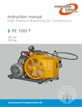
ATLANTIC 100
Page 1
This manual contains operating instructions and maintenance schedules for the high pressure breathing air compressors. Operators
must read and understand all information inside the manual.
ATTENTION. This machine can be used only after a careful reading of this instruction manual. The machine may only
used to produce compressed air. Other use is strictly prohibited. The manufacturer and the supplier void all responsibility
for damage or injury resulting from failure to follow these instructions.
1. GENERAL INFORMATION:
Before using the machine please put your attention to this
general information:
1. Personnel engaged to operate the machine must have read the
instruction manual before beginning work, especially the safety
notices chapter.
2. Personnel may not wear long hair loose, loose clothing or
jewellery, including rings.
3. Keep all safety and danger notices on the unit complete and in
readable condition.
4. No modifications may be made to the unit which could impair
safety without first obtaining permission from the suppliers.
5. Piping must be thoroughly checked (pressure and visual inspection)
by the operator at appropriate time intervals, even if no safety related
faults have been noticed..
6. Intervals stipulated or given in the instruction manual for recurring
checks/inspections must be adhered to.
7. It is absolutely essential that the workplace is appropriately
equipped for maintenance measures.
8. Work on/with the unit may only be carried out by reliable personnel.
Observe the legal minimum age permissible.
2. GENERAL INTRODUCTION:
The ATLANTIC 100 high pressure compressors are designed to
compress air for breathing as required in diving and fire fighting
applications. The max pressure is 225 bar or 330 bar depending
on unit.
The compressor unit comprises the following major assemblies:
Il compressore è composto da:
. Compressor block
. Electric or petrol/diesel engine
. Filters
. Filling assembly
. Protection and anti-vibration frame
. Automatic condensate drain*
. Electric control system**
. Automatic switch on/off*
. ALLUMINUM frame
(*) Optional extra according to order
3. COMPRESSOR PUMP UNIT
The compressor block ATLANTIC 100 is used to compress air in the high pressure range up to 330 bar (4500 psi). The compressor
block is of a four stage, four cylinders design. The cylinders are arranged in the 1st stage on the left, 2nd stage on the right, 3rd and
4th stage on the centre side looking from the filter side. The compressor blocks are particularly suitable for continuous operation
because of their rugged design and the corrosion resistant intermediate filter and cooler assemblies. Smooth running is a particular
feature of this Nardi design. The moving parts of the driving gear are all equally balanced. This results in a vibration-free running. The
driving gear is fitted with energy saving cylinder roller bearings. The upper and lower connecting rod bearings are also roller bearings.
Crankcase, cylinders and heads are obtained from the gravity dies. Connecting rod are extracted from casting dies. Cylinder are in cast
iron inside an aluminium pipe.

Instruction Manual
ATLANTIC 100
Page 2
Description
1. Intake Filter
2. 1st stage
3. Inter-cooler 1st stage
4. 2nd stage
5. Inter-cooler 2nd stage
6. 3rd stage
7. Inter-cooler 3rd stage
8. 4th stage
9. Inter-cooler 4th stage
10. Oil indicator
4. TECHNICAL DATA
Compressor unit ATLANTIC 100
Operating pressure PN 200 PN300
Delivery * 100 L/min. 100 L/min.
Final pressure safety valve 225 Bar 330 Bar
Compressor block ATLANTIC 100
Number of stages 4
Number of piston 4
Cylinder bore stage 1 60 mm
Cylinder bore stage 2 38 mm
Cylinder bore stage 3 19 mm
Cylinder bore stage 4 9,5 mm
Piston stroke 23 mm
Intermediate pressure stage 1 2,5 Bar
Intermediate pressure stage 2 15 Bar
Intermediate pressure stage 3 55 - 65 Bar
Intermediate pressure stage 4 225 - 330 Bar
Oil capacity 0,350 L.
Oil Type SHELL CORENA P150
Max permissible ambient temp. -5°C Min. +45°C Max. (+25°F Min. +113°F Max.)
Max permissible inclination of compressor 20°
Max dampness 80%
Max sea level 2000 m sea level
Weight 25 Kg.
Drive engine Mono phase Three phase
Type engine 110–240 Volt / 50–60 Hz 230-400 Volt / 50-60 Hz
Power 3,0 Hp 2poli
Speed 2850 r.p.m.
Type of enclosure IP 55
Current rating 16,5 A (240 Volt) – __,_ A (110 Volt)
Petrol engine ROBIN EX17 6,0 Hp 4 Stroke
Switch on/off MANUAL
Cubic capacity 169 ml.
Power 2,9 Kw-4,00 HP / 3600 r.p.m.
5. SAFETY MEASURES
5.1. Fundamental safety notices:
Important instructions concerning the endangerment of personnel, technical safety and operating safety will be specially emphasized by
special marks placing on the machine.
For safety reasons you can find some components mounted on the compressors in order to prevent damages. These parts must not be
changed or removed in any case. Before please consult our technician.

Instruction Manual
ATLANTIC 100
Page 3
5.2. Authorized use :
The unit is built according to state of the art technology and established safety technical regulations. Nevertheless, its use can cause
danger to life and limb of the operator or third parties or damage to the machine and other equipment. Operate the unit only in
technically perfect condition in accordance with regulations and safety danger notices detailed in the instruction manual. The
manufacturer/supplier is not responsible for damage resulting from a wrong utilisation of the machine. The user alone is responsible for
this risk. The compressor is built to produce top quality breathing air according to DIN EN 12021 rules.
5.3. Safety notices for operation
:
- Ensure that only trained personnel work with the machine.
- Filling hoses must be in satisfactory condition and threads undamaged.
- Ensure intake air is free from noxious gas, exhaust fumes and solvent vapour.
- The use of petrol and diesel compressors is forbidden in indoor place.
- Check the unit externally for damage and faults periodically. Inform the department/person responsible immediately if anything is not
as is should be (including operation). If necessary, shut the machine down immediately and make it safe.
Observe switching on and off processes and monitoring indications according to the instructions manual.
- Use only Nardi original parts and equipments.
- Drain the valve regularly if manual drain valve. Check every ten minutes the valve if automatic drain valve.
- Switch off the machine when do not use it.
- Clean oil, fuel or care products from, the machine, in particular the connections and screw joints, before carrying out
maintenance/repair work. Do not use aggressive cleaning fluid. Use a fibre-free cleaning cloth.
- Completely remove all covers/seals after cleaning.
- Use only original fuses with specified current rating. If there is a failure in the electric energy supply, shut the machine/unit down
immediately.
- Work on electric units or operating equipment may only carried out by a qualified electrician or by a person under the instruction and
supervision of qualified electrician according to electric technical regulations.
- The electrical equipment of a unit must be regularly checked.
- When working in small rooms, observe any national regulations.
- Depressurize system and pressure lines before commencing repair work.
- With regard to oil, grease and other chemical substances, observe the relevant safety rules for the product.
- When switching on the machine, check the arrow to ensure correct direction of rotation of the drive motor.
5.4. Electrical installation:
For installation of electrical equipment observe the following:
In the annex of this instruction manual you will find the standard schematic diagrams valid for the respective compressor unit.
Observe regulations of local electricity supply company.
Connection must be carried out by an expert only.
Ensure correct installation of protective conductor.
Check conformity of motor and control device tension and frequency with those of electric network.
ATTENTION: check the correct direction of the fan.
6. OPERAZIONI PER L’AVVIAMENTO:
6.1 Preparation for operation.
WARNING: this machine is built to produce breathing air. It is not suitable for compression of oxygen. Explosion occurs if an oil
lubricated compressor is operated with pure oxygen or gases with oxygen content of more than 21%!
All compressor units are tested prior to delivery to the customer, so after correct installation of the unit there should be no problem
putting it into operation, observing the following points:
Prior to first operation read Instruction Manual carefully. Make sure that all persons handling the compressor and the filling station are
familiar with the function of all controls and monitors.
Immediately after switching on the system for the first time check the direction of rotation of the motor for compliance with the arrow
on the unit. If motor turns in the wrong direction, the phases are not connected properly. Shut down unit immediately and interchange
two of the three phase leads in the switch box. Never change leads at the motor terminal board.
Prior to each operation check the oil level. Only for petrol unit: - check engine oil level according to manufacturer’s instruction manual -
check fuel tank. Top up if necessary - open fuel shut-off valve.
Every time the unit is started up check all systems for proper operation. If any malfunction is observed stop unit immediately and find
the cause of the fault or call the service department.

Instruction Manual
ATLANTIC 100
Page 4
6.2. Starting the unit:
Unit with electric engine without compressor control system:
The motor is switched on manually by pressing the start button. Machine does not be left alone during working. Check continuosly the
right function.
On units without automatic condensate drain, the manual condensate drain valves have to be opened before starting the unit, as soon
as the unit is running the valves can be closed again. Every 8/10 min drain the valves.
Units with electric engine with automatic control system:
This model is delivered with an automatic control system.
Before starting check point 6.1 and then press ON button. Switch off the machine pressing STOP button.
Units with petrol engine:
Open condensate drain valves on the filters to release pressure, so that motor start without load. Set choke to position START. Start
engine with recoil starter or crank handle. As soon as motor runs smoothly return choke to normal operating position.
For all units:
Close condensate drain valves tightly and run unit to final pressure. Check final pressure safety valve and pressure gauge. As soon as
final pressure is reached and final pressure safety valve blows off, open condensate drain valves and drain condensate - unit is ready for
filling operation.
7. FILLING PROCEDURE:
7.1. Connecting the bottles:
WARNING: Filling hoses must be in satisfactory condition and threads undamaged. Pay particular attention to damage on the interface
from hose fitting to hose. If the rubber is scored, hose must be discarded otherwise water can enter and attack wire gauze causing it to
rust.
Normally connectors are allowed for pressures up to 200bar (2.850psi).
Please follow the process below:
- Connect air bottle to filling valve.
- Open filling valve.
- Open bottle valve-bottle will be filled. .
- Switch on the compressor.
- Upon reaching final bottle pressure close bottle valve first, then filling valve by returning handle to closed position.
- Remove compressed air bottle.
- Depressurize unit before opening valve-A to avoid damage to the change - over device.
If it is necessary more pressure of 220bar please ask for the suitable material: safety valves and connectors are
different.
8. MAINTENANCE :
8.1. Maintenance record:
We recommend that all maintenance work is recorded in a service book, showing the date and details of the work carried out. This will
help to avoid expensive repairwork caused by missed maintenance work.
Please fill in the appropriate lines to show what maintenance work has been carried out, and sign and date.
Remember:
1– always shut down and decompress the complete system prior to carrying out any work on the compressor;
2– never repair pressure lines by soldering or welding;
3– only use original spares for maintenance or repair work.

Instruction Manual
ATLANTIC 100
Page 5
8.2. Maintenance schedule:
After first 25 operating hours Date Segnature
Clean intake filter and intake filter cartridge
Check Oil level
( Max. RED POINT )
Cartuccia Filtro Carboni – setaccio
Check tightness of all cooler-pipes and couplings
Check tightness of O-rings
Check functioning and tightness of filling valve
Check zero position on final pressure gauge when
depressurized
After first 50 operating hours, at least annually Date Segnature
Oil change 350 ml.
Check and clean intake filter element 1st stage
Check filter and cartridge
After first 500 operating hours, at least annually Date Segnature
Valve change
Change intake filter element 1st stage
Check blow-off pressure of final pressure safety valve
After repair work
Date Segnature
Check functioning and tightness of filling valve
Clean intake filter element 1st stage
Check tightness of O-rings
Check zero position on final pr
essure gauge when
depressurized

Instruction Manual
ATLANTIC 100
Page 6
9. MAINTENANCE WORK
This chapter contains the maintenance work as well as short functional description for each component.
9.1. Lubrication :
The lubrication system is a Splashed lubrication. Mechanic lubrication by connecting-rod movement. Connecting-rod has a metal
piece below that splashing in the oil during the fast movement causes a spray inside the cylinder.
9.2. Type of oil :
Using the correct oil is of vital importance for life and maintenance of the compressor. Nardi has a particular oil studied and tested for
the best operation of his machine. Depending on the application of the compressor the requirements placed on the oil are:
- low deposits
- No carbonizing effect, especially in the valves
- Good anti-corrosive properties
- For breathing air application, also physiological and toxicological suitability.
Due to the thermal load on the compressor only high quality oil should be used. You are recommended to restrict oils to those which
have been approved by us: oil for not mixed air (21% O²).
9.3. Oil change :
Please follow the procedure as below:
- Ensure to have a sufficient quantity of oil.
- Run compressor warm.
- Remove red cap from oil filler neck and drain oil while still warm by means of oil
drain plug.
- Remove oil filter.
- Mount a new filter element.
- Fill new oil though filler neck to Max.—mark at sight gauge.
9.4. Changing the oil type:
To avoid severe damage to the compressor unit when changing the oil type, the following measures should be strictly adhered to:
- Follow the procedure Chapter 9.3.
- Change or clean all parts with old oil.
- After approx. 10 operating hours check lubricating oil for degree of contamination, and change oil again if necessary.
- Fill compressor with the new oil and do not mix different oils.
- Refill compressor with same oil, only.
9.6. Intake filter
A dry micronic filter is used to filter intake air. The filter cartridge must be cleaned or changed at regular intervals according to
maintenance schedule. Do not use any cleaning fluids which are a hazard to respiration.
Please clean intake filter as following:
- Remove micronic filter cartridge.
- Clean with brush or by blowing air inside out.
- Change with a new filter and make sure that top cover is installed properly.
9.7. Intermediate separator
Separators are designed to remove water and oil accumulation due to cooling the air down after the compression process. An
intermediate separator is mounted on the compressor between stages.
Clean filter element as follows:
- Switch off the compressor and depressurize separators.
- Remove piping connected to filter head. Screw off union nut. Remove filter head.
- Clean filter element using hot soapy water and blow dry with compressed air.
- Replace O-ring.
- Close the filter strongly.

Instruction Manual
ATLANTIC 100
Page 7
9.8. Coal filter cartridge :
Coal filter cartridge removes water condensation and oil by a chemical system
not mechanical. Activated carbon and molecular sieve absorb water and oil
purifying breathing air according to DIN EN12021.
Filter has two safety systems. The first one has a hole closed when the cartridge
has put inside. It is not possible to refill cylinders without cartridge. The second
one is designed to prevent pressurizing in the absence of the filter cartridge. A
bore provided in the filter bottom is sealed air-tight only if the cartridge is in
place. Without cartridge the venting bore is not sealed, the air escapes into the
atmosphere and no pressure can be built up.
The filter system is subject to dynamic load. It is designed for a certain number
of load cycles, which originate from an abrupt pressure loss at condensate drain.
After 500 operating hours an inspections have to be arranged by the operator.
After reaching the max. number of load cycles: 8000 cycles at 300Bar or
21000cycles at 225Bar the filter assembly must be replaced. Approximately,
with 4cycles per hour at 300 bar filter must be changed after 2000 operating
hours instead at 225 Bar after 5000 operating hours..
9.9. Filter maintenance :
The cartridge in the picture removes water and oil
Please follow the procedure below:
- Depressurize system before starting any maintenance work.
- Dry inside of filter housing with a clean cloth before installing new cartridge and check for
corrosion. Change if necessary.
- Check the O-ring and change it if damaged.
- Change cartridge before reactiving a compressor unit.
The number of operating hours or the amount of possible bottle fillings per filter cartridge can be
determinated taking into consideration the ambient temperature and the cartridge used.
To avoid any ranger to your health or damage to your unit, change used up cartridges in good time.
Never fill used up cartridges yourself. The filter material was chosen specifically by Nardi
compressori for each kind of application. Never remove replacement cartridge from packaging prior
to actual use otherwise highly sensitive molecular sieve will absorb water vapour from surrounding
air and cartridge saturated.
9.10. Lifetime of filter cartridge :
Tempi cartuccia / Lifetime off Cartridge
ATLANTIC 100 (225 BAR)
45
34
24
20
15
54
34
27
20
16
12
43
10°C / 45°F
15°C / 59°F
20°C / 68°F
25°C / 77°F
30°C / 86°F
35°C / 95°F
40°C / 104°F
Temperatura °C / Temperature °F
Tempo in ore / Hours
Poco Umido/Little Damp Molto Umido/Higt Dam p

Instruction Manual
ATLANTIC 100
Page 8
9.11. Valves:
The valve heads of the individual stages form the top part of
the cylinders. The intake and pressure valves are fitted inside
the valve heads. Note that the valves are operated by the flow
of the medium. On the suction stroke, the intake valves open
and the medium flows into the cylinders. At the start of the
compression stroke the intake valve closes and the medium
opens the pressure valve.
Please follow the instructions below for changing the valves:
Always replace valves as a complete set.
Carefully clean dirty valves.
Observe the correct sequence when fitting together again.
Check individual components for excessive wear. If the valve seat
and valve disks are dented, replace the valves.
Use only satisfactory gaskets and O-rings on reassembly.
After finishing all maintenance work on the valves, turn the
compressor manually and check whether all items have been
correctly installed. After 30 minutes after starting, switch off the unit
and check again.
Replace the valves every 500 operating hours to avoid fatigue
failure.
9.12. Valve change:
Changing the valve of the 1st stage:
Put the attention at the picture and check that the mark ‘T’ Is really at the
top. Remove gaskets and O-rings if damaged.
Changing the valve of the 2nd stage:
Please follow the procedure below:
- Unscrew the intake and pressure lines from the cylinder head.
- Unscrew the screw of valve-cover.
- Clean intake and pressure valves and check for wear. Valve seats and plate valves
must not show any signs of wear or damage. Replace damaged parts.
- Assembly is performed in the riverse sequence of removal.
- Check the pressure valve function and stoke by lifting the valve plate.
- Check O-rings and replace them if damaged.
- Fix the valve-cover.
Reconnect the intake and pressure lines.
Changing the valve of the 3rd – 4th stage:
Please follow the procedure below:
- Unscrew the intake and pressure lines from the cylinder head..
- Fix the head
- Unscrew the intake valve body.
- Clean intake and pressure valves and check for wear. Valve seats and plate valves
must not show any signs of wear or damage. Replace damaged parts.
- Assembly is performed in the reverse sequence of removal.
- Peen the cylinder head on the screw.
- Check the pressure valve function and stoke by lifting the valve plate.
- Check O-rings and replace them if damaged.
- Fix the head at cylinder.
- Reconnect the intake and pressure lines.

Instruction Manual
ATLANTIC 100
Page 9
Space Parts ATLANTIC 100:
N° Pasts
Description
Quantity
N° Pasts
Description
Quantity
N°
Description
Quantity
A001
Metal
Co
ver Fan
1
A020
Compressor crankcase
1
A039
Safety O
-
ring piston 1st
–
2nd
4
A002
Fan
1
A021
Thickness
2
A040
Piston 1st stage
1
A003
Pulley
1
A022
Eccentric
4
A041
Piston rings 1st stage
1 Set.
A004
Compressor shaft
1
A023
Roller bearing
4
A042
Piston pin 1st stage
1
A005 Key 1 A024 Roller bearing 4
A043 Piston pin 2nd stage 1
A006
Screw
1
A025
Connecting rod 1st
–
2nd Stage
2
A
044
Pis
ton 2nd stage
1
A007
Screw
1
A026
Connecting rod 3rd
–
4th Stage
2
A045
Piston rings 2nd stage
1 Set.
A008
Nut
1
A027
Fl
ange
1
A046
Trickiness
connecting rod 2nd
st.
2
A009
Washer
3
A028
Nut
1
A047
Piston
4th
stage
1
A010
Screw
4
A029
Cover Oil seal
1
A048
Piston rings
4th
stage
Set. 1
A011
Metal Wire
1
A030
Visual level plug oil
1
A049
Bracket Compressor
1
A012
Oil seal
1
A031
Roller bearing
2
A050
Oil cap
1
A013 Screw 16 A032 Piston pin 3rd – 4th stage 2
A051 O-ring 1
A014
Flange
1
A033
Safety O
-
ring piston
3rd
–
4th
4
A052
Vat Oil Vapour
1
A015
O
-
ring
2
A034
Piston 3rd stage
1
A053
Filter
Olio
vapour
1
A016
Bearing
3
A035
Piston rings 3rd stage
1 Set.
A054
O
-
r
ing
1
A017
Circlip ring
2
A036
Piston
rings 3rd stage
1 Set.
A055
Cork
1
A018
Thickness
1
A037
Trickiness
connecting rod 1st stage
2
A056
Screw
6
A019
Flange
1
A038
Roller bearing 1st
–
2nd stage
2

Instruction Manual
ATLANTIC 100
Page 10
Space parts ATLANTIC 100:
N°
Des
criptor
Quantity
N°
Description
Quantity
N°
Description
Quantity
A057
O
-
ring
1
A077
Connections
L 1/4''
tube 8mm
1
A095
Screw
1
A058
Cylinder
1st Stage
1
A078
Inferior body valve 2
nd
stage
2
A096
O
-
r
ing
1
A059
Cylinder
Gasket 1st Stage
1
A079
Valve plate 2
nd
stage
2
A097
Plate valve 4
th
stage
1
A060
Screw
1
A080
Spring valve
2
nd
stage
2
A098
Spring valve 4
th
stage
1
A061
Lamella
1
A081
Central
bod
y valve 2
nd
stage
2
A099
Washer Valve Head
1
A062
Valve plate
1
A082
O
-
ring
2
A100
Head 4
th
stage
1
A063
Lamella
1
A083
Body suction valve 2
nd
stage
2
A101
Connection
L 1/4''
1
A064
Washer
1
A084
O
-
ring
2
A102
Connection
L 1/4''
1
A065 Dado 1 A085 Cover valves 1 A103 Screw 4
A066
Top Gasket 1
st
stage
1
A086
Screw
6
A104
Head 3
rd
stage
1
A067
Head 1
st
st
age
1
A087
Screw
4
A105
Spring 3
rd
stage
1
A068
Connection
L 1/4''
tube 10mm
1
A088A
Intake v
alv
e
1
A106
Plate valve 3
rd
stage
1
A069
Screw
4
A088S
Outtake valve
1
A107
Seal washer
Head 3
rd
st
age
1
A070
Complete suction Filter
1
A089
O
-
ring
1
A108
Inferior body valve 3
rd
stage
1
A072
Suction filter cartridge
1
A090
O
-
ring
1
A109
O
-
ring
1
A073
C
ylinder 2
nd
stage
1
A091
Cylinder 4
th
stage
1
A110
Cylinder 3
rd
Stage
1
A074 O-ring 1
A092
O-ring 2 A111 O-ring 2
A075
Head 2
nd
stage
1
A093
Connections
L 1/4'‘
tube 8mm
1
A112
Connection
a T 1/4"
1
A076
Connections T 1/4
''
tube 10
mm
1
A094
Aluminium
cylinder
3
rd
–
4
th
stage
1

Instruction Manual
ATLANTIC 100
Page 11
Space parts ATLANTIC 100:
N° Description Quantity N° Description Quantity
A113
Intercooler 1
st
–
2
nd
St
age
1
A121
Intercooler 3
rd
Stage
–
separator
1
A114
Fixing tube 1
st
–
2
nd
Stage
2
A122
Fixing tube 3
rd
-
separator
2
A115
Screw
2
A123
Screw
3
A116
Intercooler 2
nd
–
3
rd
Sta
ge
1
A124
Nut
2
A117
Fixing tube 2
nd
–
3
rd
Stage
2
A125
Intercooler 4
th
Stage
–
separato
r
1
A118
Screw
2
A126
Fixing tube 4
th
Stage
-
separ
ator
2
A119 Bracket tube 3
rd
Stage 1 A127 Fixing tube 4
th
Stage - separator 2
A120
Screw
3

Instruction Manual
ATLANTIC 100
Page 12
Space parts ATLANTIC 100:
N° Description
Quantity
mpres.
N° Description Quantity
N°
Description Quantity
A128
Connection L 1/4'' tube
8mm
1
A143
Plug filter separator Inferior
1
A157E60HZ
Belt for electric engine 6
0 Hz
1
A129
Screw
4
A144
Condensate drain valve complete
2
A157G
Belt for gasoline engine
1
A130
Plug
1/4''
6
A145
Screw
4
A158E50HZ
Pulley for electric engine 50Hz
1
A131
Connection 1/4 Tube
8mm
2
A146
Screw
4
A158E60HZ
Pulley for electric engine
60
Hz
1
A132
Plug filter separator
1
A147
Washer
4
A
158G
Pulley for gasoline engine
1
A133
O
-
ring
2
A148
Body carbons filter Atlantic
1
A159P
Cover belt electric compressor
1
A134 Element separator 2 A149E Filter cartridge ATLANTIC electric 1 A159G Cover belt gasoline compressor
1
A135
Elemen
t separator
2
A149G
Filter cartridge
ATLANTIC
gasoline
1
A160
Screw
2
A136
-
225
Safety valve
225 Bar
1
A150
O
-
ring
1
A161
Washer
6
A136
-
330
Safety valve 3
30 Bar
1
A151
O
-
ring
1
A162
Metal Wire
Cover fan
1
A137
Tube separator
–
fil
ter
1
A152
O
-
ring
1
A163
Washer
6
A138
Connection
L 1/4'' tube
6mm
3
A153
O
-
ring
1
A164
Screw
4
A139
Body
filter separator
1
A154
Plug carbons filter
Atlantic
1
A165
Connection
1/4"
for hose
1
A140
Drain valve housing
1
A155
Screw
1
A166
Screw
1
A14
1
TEFLON
nut
1
A156
Metallic
Cower belt
1
A142
Screw of discharge
1
A157E5
0HZ
Belt for electric engine
5
0 Hz
1
/