Page is loading ...

OPERATING MANUAL
for
Separator Compact
Version: I- 2014

II
Operating Manual for Bauer Separator Compact
S
Thank you for buying a BAUER separator!
This operating manual is an important document that describes the operation and maintenance of
the BAUER SEPARATOR.
All information contained in this manual is based on the latest product details available at the time of
printing. If you need still more information, please ask your dealer or contact the BAUER company
directly.
Please note that the content of this manual neither constitutes part of nor alters in any way any previ-
ous or existing agreement, promise or legal relationship. BAUER’s obligations are based solely on
the respective purchase contract, which also contains the complete and only valid warranty agree-
ment. Said contractual warranty is neither extended nor limited by the content of this manual.
The BAUER SEPARATOR is designed for safe and reliable operation provided it is operated in ac-
cordance with this operating manual.
You should therefore study this manual thoroughly before starting your BAUER SEPARATOR! Strict-
ly observe all instructions pertaining to system handling, operation and service!
If these conditions are ensured, the BAUER SEPARATOR will operate to your complete satisfaction
for many years to come.
The content of this operating manual is the intellectual property of the company BAUER GesmbH
and/or its supplier companies. The available information may only be used in connection with the cre-
ation of specification-compliant documents in the course of an order from the BAUER company.
Without express written permission from the BAUER company, no reproduction or sharing of this
operating manual is permitted, even in excerpts.
The BAUER company reserves the right to make changes at any time without notice and without as-
suming any liability!
In the interests of a clearer presentation and due to the large number of possibilities, this operating
manual does not contain all detailed information and, in particular, cannot address every conceivable
operating and maintenance situation.
WARNING
Failure to follow this manual may cause personal injury or damage the
equipment!
NOTE
This manual is to be considered an integral part of the BAUER SEPARATOR. Sup-
pliers of both new and used systems are advised to put down in writing that they
delivered the manual together with the system.
Please make this manual available to your staff. State the pump type and serial number of your
BAUER SEPARATOR in all inquiries, correspondence, warranty problems or parts orders. You will
find this information on the type plate riveted onto the screen housing of the separator.
We wish you great success with your BAUER SEPARATOR!

Operating Manual for Bauer Separator Compact
1
PRODUCT DETAILS
Type designation:
Separator Compact
Serial number
1
:
Dealer:
Name:
Address:
Tel. / fax:
Shipping date:
Producer of the machine:
Röhren- und Pumpenwerk BAUER Ges.m.b.H.
Kowaldstr. 2
A - 8570 Voitsberg
Tel.: +43 3142 200 - 0
Fax: +43 3142 200 –320 /-340
Owner or operator:
Name:
Address:
Tel. / Fax:
Note: Make a note of the type designation and serial number of your separator and its accessories.
Include these numbers along with all contact with your dealer.
1
It is very important to include with all guarantee claims and all correspondence related with this ma-
chine the entire serial number group, including all letters, both for the machine and for its relevant
components. This point cannot be stressed enough.

2
Operating Manual for Bauer Separator Compact
S
TABLE OF CONTENTS
1 GENERAL SAFETY INSTRUCTIONS ............................................................................................................... 4
1.1 Warnings and Symbols ................................................................................................................................ 4
1.2 Duty to Furnish Information ......................................................................................................................... 4
1.3 Product Liability............................................................................................................................................ 4
1.4 Qualified Operators ..................................................................................................................................... 5
1.5 Intended Use ............................................................................................................................................... 5
1.6 Unauthorized Modification and Manufacture of Replacement Parts ........................................................... 5
1.7 Disposal ....................................................................................................................................................... 5
2 GENERAL INSTRUCTIONS FOR SAFETY AND ACCIDENT PREVENTION .................................................. 6
3 FUNCTION DESCRIPTION ................................................................................................................................ 9
4 SETUP OF THE SEPARATOR ........................................................................................................................ 10
4.1 Installation Diagram ................................................................................................................................... 10
4.2 Condition of the BAUER Separator upon Delivery .................................................................................... 10
4.3 Required Tools .......................................................................................................................................... 10
4.4 Features, Identification and Information .................................................................................................... 11
4.5 Type plates - Information Signs ................................................................................................................. 12
4.5.1 Information on the Separator Type Plate ........................................................................................... 12
4.5.2 Information Signs................................................................................................................................ 12
4.6 Separator Technical Data .......................................................................................................................... 12
4.7 Setup and Assembly .................................................................................................................................. 13
4.8 Complete System ...................................................................................................................................... 14
4.8.1 Inflow Setup ........................................................................................................................................ 15
4.8.2 Drainage Line ..................................................................................................................................... 15
5 ELECTRICAL CONNECTION .......................................................................................................................... 16
5.1 Setup and Operation of the Motor ............................................................................................................. 17
5.2 Condensate Hole ....................................................................................................................................... 17
5.3 Installation Without Switch Cabinet ........................................................................................................... 17
6 PREPARATION FOR INITIAL STARTUP ........................................................................................................ 18
7 INITIAL STARTUP ........................................................................................................................................... 18
7.1 Configuration Instructions .......................................................................................................................... 18
7.2 Solid Cake Formation ................................................................................................................................ 19
7.3 Configuration to Stabilize the Solid Cake .................................................................................................. 20
7.3.1 Cake Too Firm .................................................................................................................................... 20
7.3.2 Cake Too Soft .................................................................................................................................... 20
7.4 Additional Instructions for Flawless Operation .......................................................................................... 21
8 WINTER OPERATION ..................................................................................................................................... 21
9 TEST FOR SEPARATION CAPABILITY ......................................................................................................... 22
10 LIQUID CLEANING .......................................................................................................................................... 23
11 IMPORTANT ASPECTS TO BE CONSIDERED DURING OPERATION ........................................................ 23
12 TAKING THE SEPARATOR OUT OF OPERATION ....................................................................................... 23

Operating Manual for Bauer Separator Compact
3
13 MAINTENANCE AND INSPECTION ................................................................................................................ 24
13.1 Gearbox and Motor ................................................................................................................................ 24
13.1.1 Supply with Sealing Medium ............................................................................................................... 24
13.2 Inspection of the Sieve and the Guide Rails .......................................................................................... 25
13.3 Inspecting and Reinstalling the Sieve .................................................................................................... 27
13.4 Inspecting and Reinstalling the Screw ................................................................................................... 28
13.5 Evaluation Criteria for the Screw and Sieve with Regard to Wear and Refurbishing ............................ 29
13.6 Summary of Maintenance and Inspection Intervals ............................................................................... 30
14 PROBLEMS - TROUBLESHOOTING.............................................................................................................. 31
14.1 Principles of a “Normal” Operating Condition ........................................................................................ 31
14.2 Troubleshooting ..................................................................................................................................... 32
15 ACCESSORIES ................................................................................................................................................ 35
15.1 Separator Control ................................................................................................................................... 35
15.1.1 Motor protection circuit breaker F1 ..................................................................................................... 35
16 NOTES .............................................................................................................................................................. 36
17 CONFORMITY DECLARATION ....................................................................................................................... 37

4
Operating Manual for Bauer Separator Compact
S
1 GENERAL SAFETY INSTRUCTIONS
This operating manual contains important information that must be observed during setup, operation
and maintenance. For this reason, it must always be read and observed very carefully by the installa-
tion technician as well as the qualified personnel. It must always be available at the usage location of
the machine.
If the installation and maintenance are not carried out according to the operating manual, all warranty
claims due to faults become void.
The customer is responsible for the proper setup of all equipment. Read the instructions before as-
sembling or installing the machine. Promised performance characteristics of the machine and the add-
on components as well as the fulfillment of any warranty claims are dependent on compliance with
these instructions.
The CE mark applied by the manufacturer provides external verification of the ma-
chine’s conformity with the provisions of the Machinery Directive and with other
pertinent EC directives.
1.1 WARNINGS AND SYMBOLS
The following notes and warnings are used in this operating manual for especially important instruc-
tions:
DANGER
Information, requirements or prohibitions to protect against serious injury or
property damage.
WARNING
Special information on preventing minor injuries or requirements and prohibi-
tions to prevent damage to the machine.
NOTE
Special instructions to simplify working with the machine or to aid in efficient use
of the machine.
To prevent malfunctions that could directly or indirectly result in serious injuries or property
damage, it is equally important to comply with any other instructions concerning transport,
assembly, operation and maintenance as well as reference data (in the operating manual, the
product documentation or on the equipment itself).
1.2 DUTY TO FURNISH INFORMATION
When passing the machine on to a new owner, the customer is obliged also to hand over the operating
manual to the new owner. The recipient of the machine must be instructed with reference to the men-
tioned regulations.
Should you encounter difficulties in understanding this manual or other instructions, contact the re-
spective dealer or the BAUER company for
any necessary clarifications.
1.3 PRODUCT LIABILITY
According to the Product Liability Act, every farmer is an entrepreneur!
In accordance with Section 9 PHG (Product Liability Act), liability for damage to physical property
caused by defective products is expressly excluded. This exclusion of liability also applies to parts not
manufactured by BAUER itself but purchased from external suppliers.

Operating Manual for Bauer Separator Compact
5
1.4 QUALIFIED OPERATORS
These are persons who on behalf of their training, experience and instruction as well as their
knowledge of relevant standards, rules, precautions to be taken for accident prevention and prevailing
operating conditions have been authorized by the person in charge of system safety to perform the
respective tasks required and in doing so are able to recognize and avoid potential hazards. The statu-
tory minimum age for the operating and maintenance personnel must be observed. Among other
things, knowledge of first aid procedures is also required.
1.5 INTENDED USE
The BAUER separator is designed exclusively for solid-liquid separation in agricultural applications
(intended use).
Any use of the machine beyond this intended use is considered non-conforming. The manufactur-
er is not liable for damage resulting from such non-conforming use, the sole liability for damage
from non-conforming use lies with the user.
Intended use also includes compliance with manufacturer’s operating, maintenance and service
instructions.
The BAUER separator may be used and operated only by persons who are familiar with the sys-
tem and aware of the hazards involved.
All relevant rules for accident prevention as well as any other generally accepted rules and regula-
tions relating to safety, occupational medicine and traffic laws must be strictly observed.
Unauthorized modifications to the machine release the manufacturer from liability for damage re-
sulting from such modifications.
1.6 UNAUTHORIZED MODIFICATION AND MANUFACTURE OF REPLACEMENT PARTS
Modifications or alterations to the machine are only permitted after consultation with the manufacturer.
Original replacement parts and authorized accessories from the manufacturer serve the interests of
safety. The use of other parts voids the manufacturer’s liability for any resulting consequences.
The replacement parts used must correspond to the technical requirements established by the manu-
facturer of the system. The replacement and wearing parts delivered with the machine or via subse-
quent orders satisfy this condition.
1.7 DISPOSAL
The machine must be disposed of according to the local disposal regulations.
The user must ensure safe and environmentally friendly disposal of operating materials and ancillary
materials as well as replaced parts. Dispose of oil, grease, and filters in accordance with regulations!

6
Operating Manual for Bauer Separator Compact
S
2 GENERAL INSTRUCTIONS FOR SAFETY AND ACCIDENT PREVEN-
TION
Check the operational safety of the machine before every start !
All regulations of public authorities that apply to the operation and maintenance of the system must be strict-
ly observed.
In addition to the operating manual, all generally applicable statutory and otherwise mandatory regulations
on accident prevention and environmental protection must be separately prescribed and observed.
Such obligations may concern, for instance, the handling of hazardous substances, the provision and wear-
ing of personal protective gear or traffic and road safety regulations.
The operating manual should be extended with the instructions for taking into account special operating
conditions, such as with regard to the work organization, work processes and the active personnel. The su-
pervisory and reporting obligations of the operator must also be clearly regulated.
To ensure your safety and the safety of your employees, every person who is responsible for operating the
system must also be familiar with these obligations. It is too late for this when the system is already running!
The personnel assigned to operating the plant must have read the operating manual and in particular the
section “General Instructions for Safety and Accident Prevention" before starting work.
Every person must be aware of the safety measures that must be complied with during work on electro-
mechanical components and machines.
Only trained personnel may enter the hazard zone of the machine.
Only trained personnel may be assigned to work with the machine. The respective competencies of the
personnel for the operation, setup, maintaining and repair of the machine must be clearly defined. It must
also be ensured that only appropriately authorized personnel work on the system.
Personnel who are being trained, taught, instructed or are participating in a general training program may
only work on the system under the constant supervision of a person experienced in operation of the system.
The safety- and risk-conscious work by the personnel in compliance with the operating manual must be
checked at least at certain intervals.
The personnel assigned to operate the machine may not have:
Exposed long hair
Loose clothing
Jewelry, including rings and drop earrings
Such items could get stuck and/or drawn into the machine, resulting in possible injuries.
The operating personnel of the system must be familiarized with the fire alarm and fire-fighting options.
The wearing of personal protective gear such as hearing protection, safety glasses, safety shoes, etc. dur-
ing operation of the system must be required by means of rules or regulations.
All safety information and warnings present on the machine must be pointed out, and these must be kept on
the system in a clearly visible and legible condition.
In event of safety-relevant changes to the system or its operating behavior, the system must be immediately
shut down and the fault must be reported to the competent person or office.
Replace pipelines and hoses in the specified or otherwise reasonable intervals, even if no operationally rel-
evant defect is discernible.
Intervals that are required or specified in the operating manual for regular daily, weekly and monthly inspec-
tions and tests must be complied with. Appropriate tools and equipment must be kept available for the per-
formance of such work.
Any potentially unsafe work on the machine must be avoided. The system may only be used in accordance
with its intended use. All necessary measures must be taken to ensure that the system is only operated in a
safe and fully functional condition.
The system may only be started up if all protective and safety-related features are fully functional. This in-
cludes the fact that all removable protective features, EMERGENCY STOP buttons and covers must be
present and functional.
WARNING

Operating Manual for Bauer Separator Compact
7
The system must be inspected for externally identifiable defects before it is started up each time. Any
changes that occur, including changes to the operating behavior and functional disruptions, must be imme-
diately reported to the competent party. The system must be immediately shut down and secured.
Procedures for switching the machine on and off as well as inspection of the control indicators must be car-
ried out as described in the operating manual.
Before switching on or starting up the machine, it must be ensured that no one will be endangered by the
starting up of the machine.
The correct functioning of the controller must be checked before the start of work. Before startup, all tools
and assembly aids must be stored safely to prevent accidents.
The maintenance, configuration and inspection activities and deadlines specified in the operating manual
must be complied with. The specified deadlines are maximum deadlines and may not be exceeded. Such
work as well as the replacement of components may only be performed by qualified personnel.
During transport of the separator, measures must be taken to ensure sufficient securing of the transport ar-
ea.
The required switch-on and switch-off procedures according to the operating manual and the instructions
for maintenance work must be observed during all work involving the operation, production adaptation, con-
version or configuration of the system and its safety-related features as well as all work involving inspection,
maintenance and repair.
The operating personnel must be informed of special work, repair work or conversion work in a timely fash-
ion prior to starting the work. A supervisor must always be appointed during the performance of such work.
The work area must be blocked off and secured by a wide margin during such work, if necessary. Unau-
thorized persons must be prevented from entering.
As a rule, maintenance and cleaning work as well as repairs of malfunctions may take place only with the
drive switched off and the motor at rest (switch off and lock the main switch or disconnect the supply of
electricity).
Watch out for the unexpected starting of the system.
It must be noted that a pressed EMERGENCY OFF button does not provide any protection against unau-
thorized starting of the machine.
During disassembly and assembly, large individual parts and entire assemblies must be carefully fastened
and secured to lifting equipment. Only suitable lifting equipment and load handling devices with sufficient
carrying capacity and no technical operating defects may be used. Standing or working under suspended
loads is not permitted. Grips, steps, railings, landings, platforms and ladders must be cleaned of oil, dirt,
snow and ice before all activity on the system.
If the BAUER separator is installed on an elevated platform, this must be equipped with a railing. The plat-
form should be sufficiently dimensioned to allow maintenance and service work.
Any openings in the platform must be sufficiently secured against tripping or falling through.
Access stairs must be equipped with hand rails in accordance with applicable regulations.
If access stairs cannot be used due to tight space conditions, permanently mounted ladders with back pro-
tection must be used.
Securing of personnel with suitable supporting elements is required during all maintenance work on an ele-
vated system.
During assembly work above head height, climbing aids and work platforms intended for such work or spe-
cially adapted for purposes of safety must be used. Never use system components as climbing aids. The
system and, in particular, connections and bolt connections must be cleaned of oil, grease or care agents
prior to the start of maintenance or repair work. No aggressive cleaning agents may be used. Only fiber-free
cleaning cloths may be used.
Before cleaning the system with water, steam, high-pressure cleaners or other cleaning aids, cover / tape
over all openings into which no water, steam or cleaning agents may enter for safety and/or functional rea-
sons. Electric motors and electronic switch cabinets are at particular risk. After cleaning, the applied covers
/ tape must be completely removed again.
Wear appropriate protective gear to protect against flying particles while cleaning with compressed air or
steam jets.
After cleaning, all gear oil and media lines as well as all electrical connections must be inspected for leaks,
loosened connections, abrasions and damage. Identified defects must be corrected immediately.

8
Operating Manual for Bauer Separator Compact
S
The bolt connections loosened during maintenance and repair work must be tightened again. Observe the
required tightening torques.
If it is necessary to remove safety features during maintenance, setup or repairing, the safety equipment
must be re-installed and inspected immediately after completion of the work.
Do not start the machine unless all guards and safety devices are mounted completely and in proper work-
ing position!
Protective caps and covers may not be removed.
The stickers affixed to the device with safety and warning signs provide important instructions for safe op-
eration; following these instructions is intended to keep you safe! These may not be removed.
Check the proper seat of nuts and bolts regularly, and tighten them, if needed!
When replacing operating elements with blades, use a suitable tool and wear gloves.
The system is electrically operated. Take special care when performing work in the area of electrically op-
erated system components.
Work on electrical and electronic components of the system may only be performed by a trained electrician
or otherwise appropriately trained personnel under the guidance and supervision of a trained electrician in
accordance with the applicable electrical and electronic regulations.
With regard to an ATEX 95 zone 22 certification, see the special remarks.
Never touch rotating or moving parts of the machines with hands or feet.
Never reach with hands, tools or other parts over the inflow or hopper in the area of the auger while the ma-
chine is running.
In handling slurry, always remember that the gases produced by the slurry are highly toxic and explosive in
combination with oxygen. Open flame, light checks, spark creation and smoking are therefore prohibited!
When using the retention or alternating retention method, special care must be taken in the area of the
opened sliding gates to the pre-pool before the main tank or to cross channels due to the formation of gas-
es. In addition, special care is required at stirring and withdrawal points while the stirring machines or
pumps are active!
Keep the machine clean to decrease the risk of fire!
Always ensure sufficient ventilation when working with slurry!
When working with biologically active materials in connection with the BAUER separator or connected com-
ponents, the decomposition of these materials can lead to the production of life-threatening gases, espe-
cially in enclosed spaces. Always ensure sufficient supply and exhaust ventilation and/or appropriate protec-
tive clothing before entering such areas.
DANGER
In addition to the mechanical dangers of moving parts or parts under pressure, the opera-
tion of slurry handling machines also poses risks in connection with gases produced by
liquid manure. These gases (carbon dioxide CO
2
, ammonia NH
3
, hydrogen sulfide H
2
S, me-
thane CH
4
) can result in poisoning as well as explosions.
Especially when operating mixers, stirring machines, recirculation systems, pipe nozzles
and slurry aeration systems, care must be taken that no gases can flow into the stall from
exterior tanks or containers (install siphons or sliders).
Sufficient forced ventilation of the stall area must be ensured while handling slurry in the
stall area.

Operating Manual for Bauer Separator Compact
9
3 FUNCTION DESCRIPTION
The BAUER separator serves for separating pumpable slurry (solid-liquid mixtures with relatively low
solid matter content and no foreign bodies such as metal parts, stones, wood or rags) into solid and
liquid (thin slurry) fractions. As a compact device, it combines the functions of two separators, specifi-
cally the functions of a screen and a press.
The BAUER separator is designed for sustained operation outdoors. It operates unimpaired in a tem-
perature range of 0-40 °C; in event of freezing temperatures, it must be ensured that the separator is
cleaned completely each time before being taken out of operation. Conditions of high humidity (e.g.
locations near to the coast) and extreme sunlight require special designs for the gears and motors.
Consult the manufacturer concerning such designs.
When selecting the feed pump and the overflow line, make certain that the separator is operated under
no pressure.
In the inflow area, the mixture is drained of water via gravity inside the screen. The interior auger
transports the pre-drained material horizontally toward the solid outlet. Along the last section of the
transport path, the auger presses out additional liquid, which escapes the separator through the screen
as thin slurry. The required contact pressure is applied to the escaping solid by a system consisting of
a cap loaded by a weighted lever.
The solid-liquid separation depends entirely on the type of slurry. For example, the extent to which wa-
ter can be drained differs greatly between dairy cattle, beef cattle and pig slurry. Users of the BAUER
separator have many options for optimizing the separating result.
The throughput can be increased be selecting a larger screen gap width.
The residual moisture in the separated solid decreases as the contact pressure of the output
regulator is increased.
The solid matter content in the separated liquid can be reduced with a smaller screen gap width.
The degree of solid separation is improved by smaller screen gap widths.
More information about the configuration options can be found in section 7 “Initial Startup”.
Fig. 3-1 Function description
Raw liquid manure
Transport and pressing screw (19 rpm)
Sieve element
Solid phase
Liquid phase

10
Operating Manual for Bauer Separator Compact
S
Ventilation
4 SETUP OF THE SEPARATOR
4.1 INSTALLATION DIAGRAM
4.2 CONDITION OF THE BAUER SEPARATOR UPON DELIVERY
The BAUER separator was developed by the company BAUER GesmbH. The separator is delivered as
a unit, including installed electric motor, on a pallet. The inflow element with outlet for overflow and
ventilation as well as the outlet bend are enclosed separately for easier transport and must be installed
before the initial startup.
You must connect the geared motor of the separator to the power supply of the optionally available
switch cabinet and connect this to the electricity supply. It is recommended that the corresponding
electrical control for the separator or for the separator and the Bauer submersed motor pump be pur-
chased from BAUER since it will be already adapted to the corresponding drive motors.
Connecting the supplied hoses, if included, to the inflow and discharge connections of the machine
completes the installation of the BAUER separator.
DANGER
Work on electrical and electronic components of the system may only be per-
formed by a trained electrician or otherwise appropriately trained personnel under
the guidance and supervision of a trained electrician in accordance with the ap-
plicable electrical and electronic regulations.
4.3 REQUIRED TOOLS
Special tools are not required for setting up the separator.
Standard tools for assembly and electrical tools are required for assembly, setup and disassembly.
The customer must check based on the dimensions and weight of the separator whether the available
lifting equipment (forklift, tractor with front loader, crane with corresponding belts or chains) is sufficient
for setting up the separator.
Distribution of the
solid phase
Sale of the solid
phase
Composting of
the solid phase
BAUER
Separator
Compact
BAUER MAGNUM
pump system
Distribution of the
liquid phase
via BAUER
slurry injector
Cerres
Distribution of the
liquid phase
via BAUER
Pivot or Rainstar
BAUER
submersed
motor pump
MAGNUM S
BAUER
slurry mixer
BAUER
submersed
motor stirrer
TMRW
BAUER eccentric
spiral pump Helix
Liquid
phase
Solid
phase
Inflow
Overflow
BIOGAS PLANT
Fig. 4-1 Installation diagram

Operating Manual for Bauer Separator Compact
11
4.4 FEATURES, IDENTIFICATION AND INFORMATION
To make it easier for you to familiarize yourself with your new BAUER separator, Fig. 4-2 shows you a
longitudinal section of the internal machine design.
We assist every customer in optimally selecting the right main separator components for the specific
application before it is purchased, manufactured, assembled and shipped.
1
2
3
4
6 7
8
9
10
11
12
The precise article numbers of the wearing parts and the organization of the main components can be
found in the replacement parts list.
Item Part Item Part
1 Geared motor 7 Internal brace
2 Sieve housing 8 Weights
3 Press head 9 Housing protection ring
4 Double flap with rod 10 Sieve
5 Inflow element 11 Wearing profile
6 Screw 12 Sieve guide rails
Fig. 4-2 Main components
5

12
Operating Manual for Bauer Separator Compact
S
4.5 TYPE PLATES - INFORMATION SIGNS
When you contact your dealer or communicate directly with BAUER GesmbH about wearing parts or
for technical support for your separator, you will be asked for your serial number and machine number
in order to ensure faster and more effective assistance.
The type, year of manufacture and serial number of the separator is indicated on the type plate riveted
to the screen housing near the inflow. Another type plate is located on the geared motor. Associated
details can be found in the enclosed geared motor documentation.
4.5.1 Information on the Separator Type Plate
The BAUER separator type plate contains the following information:
Separator type: Compact
Sieve used: e.g. 0.5 mm or 1.0 mm
Serial number: e.g. 1310389 (13 is the year, 10 is the month, 389 is a 3-digit counter)
4.5.2 Information Signs
The following information signs are located on the BAUER separator:
Red arrow on the mouth piece; indicates the correct rotation direction of the auger shaft
Yellow text field on the mouth piece; warns of a turning part
Yellow warning symbols on the housing shell; indicate that turning parts should not be
touched
Yellow text field on the geared motor; indicates the lubrication interval for the sealing
grease
Any damaged signs must be replaced. These can be ordered from your dealer.
4.6 SEPARATOR TECHNICAL DATA
Part name
Data
Material
auger, auger shaft
Screw with special surface harden-
ing
Steel, stainless
Slotted screen
Available gap widths 0.25 / 0.35 /
0.5 / 0.75 / 1.0 mm
Steel, stainless
Bearing housing
Gray cast iron, painted
Separator housing
Gray cast iron, painted
Inflow, overflow, ventilation
BAUER inflow element 3x socket
DN100
Steel, galvanized
Bottom outlet bend
Pipe connection socket DN100
Steel, galvanized
Motor
3 kW, 50 Hz, 400 V, IP55, F,
Underframe
Steel, stainless
Gearbox
Cylindrical gearing 19.7 rpm (50
Hz)
Oil quantity and type – see type
plate on gearbox
Gray cast iron

Operating Manual for Bauer Separator Compact
13
4.7 SETUP AND ASSEMBLY
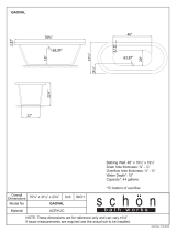
The basic dimensions of the BAUER separator for determining the dimensions of the setup location
are shown in Fig. 4-3.
The dead weight of the Separator Compact is approx. 380 kg.
A B
C
D
E
O
H
O
G
O I
K
O
L
M
N
Q
R
P
S
T
O
F
J
Fig. 4-4 illustrates a suggestion for determining the size of the separator setup location.
It is very important that a clearance of at least 1100 mm or more is ensured in front of the mouth piece
of the separator. This clearance is required to remove the auger and the screen for maintenance. It
must be possible to remove the auger and the screen for regular inspections.
Width of the setup area: No less than 2000 mm
Length of the setup area: No less than 2900 mm
The surrounding clearance around the separator should be at least 1 m.
Handrail height of the setup area: No less than 1000 mm
Make sure that the mouth piece and the functioning of the separator can be clearly seen from the
switch cabinet. (It must be possible to watch the solid cake and its discharge speed.)
Fig. 4-3 Dimensions of Separator Compact
Fig. 4-4 Size of the setup location
[mm]
A 522
B 380
C 1080
D 1389
E 833
F 100
G 100
H 100
I 100
J 109
K 319
L 710
M 932
N 1220
O 904
P 515
Q 604
R 658
S 18
T 88
At least 1100 mm
At least 1000 mm
Solid
At least 2900 mm

14
Operating Manual for Bauer Separator Compact
S
4.8 COMPLETE SYSTEM
The complete system of the press / screw separator also includes the material supply and discharge
handling.
The incoming material can be delivered by pump or from an elevated tank by means of gravity. Be-
cause the pump delivery rate cannot be precisely determined, an overflow is absolutely required in
order to protect the separator from an overload.
The pump should be designed to slightly ex-
ceed the capacity of the separator, but the
pressure on the separator should not exceed 2
m water column [0.2 bar]. A higher pressure
would damage the seal in the separator.
In order to obtain a homogeneous mixture of
solid and liquid, a stirring machine is required
when supplying the slurry via a pump or from
an elevated tank.
It is very important that the supply of material to
the separator is always controlled by the switch
cabinet.
The correct selection of the pump, the stirring
machine and the supply and disposal lines is
critically important.
When supplying the separator from an elevated
tank by means of gravity, a flow regulator may
be required in some circumstances to limit the
pressure on the separator. In this case, an
overflow is not required.
The effluent should be disposed of via an open
(and thereby ventilated) drain channel or col-
lected in a drainage pit and then pumped out in
order to avoid generating a suction effect on
the separator. The ventilation is required be-
cause otherwise particles are drawn into the
screen gap and remain stuck there, blocking
the open screen surface and impairing the
function of the separator.
The separated solid can be piled up and trans-
ported away as needed, brought away on a
conveyor belt or disposed of by container or
truck.
The supply line available with the BAUER separator as an accessory is a reinforced yet flexible tube.
This reinforced tube is resistant to negative pressure. Ventilation openings can be added to the inflow
line through the connection of a breather pipe to the inflow element. The ventilation is required for a
pump with a very high pump capacity since the high flow speed in the overflow line would otherwise
produce a siphon effect that would limit the supply to the separator and impair the separation process.
Fig. 4-5 Supply via pump
Fig. 4-6 Supply via gravity
from an elevated tank
Inflow
Stirrer
Overflow
Ventilation
Open overflow
Open drainage
Solid
Inflow
Mixer
Autom. valve
Ventilation
Inflow
Open drainage
Solid

Operating Manual for Bauer Separator Compact
15
Abb 4.7 Standard-
Inflow
Overflow
The separator must be set up so that the solid can be freely
discharged. There must be a corresponding height difference
between the solid discharge point and the ground. The volume
of the cone of discharged material can be determined based on
the setup height.
The overflow line for the raw slurry as well as the drainage line
of the separated slurry should drain without pressure into the
corresponding storage tanks.
The overflow line should be run without a “siphon” in order to
avoid a lifting effect and to ensure good separator throughput
(see also section 14 “Problems - Troubleshooting”.
Avoid winding, dipping and twisting of the pipeline and use tub-
ing that is resistant to negative pressure.
4.8.1 Inflow Setup
Screw the inflow element horizontally onto the inflow flange
(side of separator housing).
Connect the supply line to the lower horizontal connection
(socket DN100) of the inflow element. A tube of DN100 is re-
quired for this.
Connect the overflow line to the top horizontal outlet of the in-
flow element (socket DN100). A tube of DN100 is also required
for this.
A breather pipe or tube must be connected to the vertical con-
nection of the inflow element (socket DN100). This prevents the
buildup of negative pressure in the separator if the medium cre-
ates suction in the return line (siphon effect).
The breather tube should project at least 1.5 m above the over-
flow.
4.8.2 Drainage Line
Bolt the outlet bend for the separated slurry onto the outlet
flange (bottom of separator housing).
The drainage line is connected to this outlet bend. A tube of
DN100 is required for this.
Connection or transition elements for tubes (for the inflow and drainage lines) are available as acces-
sories from your dealer or the BAUER company.
NOTE
If no Bauer pump is installed, the pump for supplying the separator should have a pump rate
of at least 15 m³/h since the capacity of the separator otherwise cannot be fully utilized. To
keep pressure losses due to pipe friction low, the pipes should have a diameter of at least
100 mm (4").
NOTE
Inflow
Ventilation
Overflow
Open drainage
Open overflow
Ventilation
Abb.4-7 Inflow Setup
Fig. 4-8 Drainage line

16
Operating Manual for Bauer Separator Compact
S
5 ELECTRICAL CONNECTION
The electric motor is equipped with a terminal strip. Like all electrical connections, the external motor
control must be connected properly by a qualified electrician.
DANGER
Work on electrical and electronic components of the system may only be per-
formed by a trained electrician or otherwise appropriately trained personnel under
the guidance and supervision of a trained electrician in accordance with the ap-
plicable electrical and electronic regulations.
WARNING
Fuses do not protect the motor from overloads; they only protect the electrical
supply lines or switching systems from damage in event of a short-circuit.
The electric motor must always be protected with a motor protection circuit breaker that must be set to
the rated current shown on the type plate depending on the motor wiring. Only motor protection circuit
breakers certified according to the following standards may be used: IEC, UL, CSA.
WARNING
Set the motor protection circuit breaker to the correct value, never above the max.
rated current according to the type plate.
It is recommended that the corresponding electrical control for the separator or for the separator and
the submersed motor pump be purchased from BAUER since it will be already adapted to the corre-
sponding drive motors.
WARNING
Ensure the correct rotation direction of the auger shaft when making the electrical
connection!
In forward motion, the auger shaft turns counterclockwise
(as viewed from the output regulator toward the geared mo-
tor).
If this is not the case, two of the current-carrying conductors
at the geared motor connection or in the switch cabinet must
be swapped.
Viewing
direction
Fig. 5-1 Rotation direction of the screw

Operating Manual for Bauer Separator Compact
17
5.1 SETUP AND OPERATION OF THE MOTOR
The motors in the standard design are suitable for operation up to a maximum ambient temperature of
+40 °C (104 °F) as well as an elevation of up to 1000 m above sea level.
Conditions of high humidity (e.g. locations near to the coast) and extreme sunlight require special de-
signs for the gears and motors. Consult the manufacturer concerning such designs.
The motors must be set up to allow unimpeded inflow of fresh air and dispersal of warm air. Removal
of the fan blade and the fan housing or enclosing the motor in a housing are prohibited since the sup-
ply of cooling air would be reduced in both cases. This would cause the motor to overheat.
For use of an original BAUER control, see section 15 Accessories.
DANGER
Before making changes or inspecting the motor or switch cabinet, the machine
must be disconnected on all sides and all poles and secured against reactivation!
Always keep the switch cabinet closed!
DANGER
It must be noted that a pressed EMERGENCY OFF button does not provide any
protection against unauthorized starting of the machine.
5.2 CONDENSATE HOLE
We recommend a condensate hole on motors that are subjected to high temperature fluctuations or
extreme climatic conditions.
DANGER
A motor protection circuit breaker or a protection device with overload relay must always
be installed to protect the motor winding. Fuses do not protect the motor from overloads;
they only protect the electrical supply lines or switching systems from damage in event
of a short-circuit.
5.3 INSTALLATION WITHOUT SWITCH CABINET
If the BAUER separator was delivered or ordered without a switch cabinet, a few basic rules
must be followed in controlling the separator; otherwise, the warranty is void:
The motor must be equipped with electrical protection to prevent impermissible current loads
exceeding the rated current on the type plate.
Operating the separator without an inflow of material must be prevented by means of electrical
control since dry running would otherwise result in increased wear on the screen and auger,
which would significantly reduce their service lives. For this reason, the separator should be
started up along with the start of the medium supply and stopped between 30 and 60 seconds
after the medium supply is stopped.

18
Operating Manual for Bauer Separator Compact
S
6 PREPARATION FOR INITIAL STARTUP
Before beginning the startup process, check the following measures:
1. The separator must be firmly anchored to the ground.
2. Make sure that the mouth piece and the functioning of the separator can be seen clearly from
the switch cabinet [it must be possible to watch the solid cake and its discharge speed].
3. Check the rotation direction of the auger. As viewed from the mouth piece, the auger must turn
counterclockwise [if this is not the case, two phases must be swapped in the case of a 3-phase
power supply].
4. If the material is supplied by a pump, the rotation direction of the pump must also be checked
and corrected, if necessary.
5. A starter cake of solid material must be inserted for the startup, see section 7 Initial Startup.
6. Supply of sealing medium, see also section 13.1.1 When using grease as the sealing medium,
3 to 5 cm
3
of grease must be introduced via the lubricating nipple [see Fig. 13-1] before initial
startup in order to fill the labyrinth seal.
7. Check the oil level in the gearbox and top up, if necessary; properly dispose of old oil.
8. Check: The supply line between the pump and the separator is connected and sealed; the over-
flow line is connected and sealed; open discharge into the storage container; line for drainage
of the separated slurry connected and sealed; open discharge into storage container.
9. Motor protection circuit breaker set to required rated current; after switching on, verify the cor-
rect rotation direction; note the arrow on the mouth piece; switch off the motor again.
10. Remove the weights (minimum closing force).
WARNING
It must be ensured that no large foreign bodies such as metal parts, stones, wood
pieces or rags enter into the separator; such objects would otherwise overload
the screen and the auger in particular. It should also be noted that abrasive media
(e.g. high sand content) will reduce the service life of the components.
WARNING
The filling components must be connected such as to prevent injuries and to
comply with the statutory regulations and safeguards.
7 INITIAL STARTUP
NOTE
In order to achieve good separating results, it is necessary to mix the pumped
medium well before separating.
7.1 CONFIGURATION INSTRUCTIONS
Two weight arms and weights are available to stabilize the solid
cake and to adjust the dry matter content. These weights should
be affixed as necessary.
Fig. 7-1 Weight arms and weights
/