


Instruction Manual Junior II
i
INTRODUCTION
This manual contains operating instructions and mainten
ance schedules for the high pressure breathing air com
pressor unit
WARNING
! Pneumatic high pressure system !
The breathing air produced with the compressor units de
scribed in this manual is subject to strict quality standards.
Ignoring the operating and maintenance instructions can
lead to severe injury or death.
This compressor has been built in accordance with the EC
machine regulations 2006/42/EG. Specifications on the
noise level in accordance with the machine and product
safety law as of 01.05.2004 and the EC machine regula
tions, chapt. I, section 1.7.4. The machine has been built
according to the highest standard of technology and the
generally acknowledged safety standards. Nevertheless,
operation could still cause danger for the operating per
sonnel or third parties, or result in damage to the machine
and other values. The machine may only be used to pro
duce compressed air as specified in this manual. Other use
is strictly prohibited.
All instructions should be observed and carried out in the
order laid down to prevent damage and premature wear
to the equipment.
The manufacturer and the supplier void all responsibility
for damage or injury resulting from failure to follow these
instructions.
Edition January 2010
2010 BAUER Kompressoren GmbH, München
All rights reserved
Junior II

A
B
C
Instruction Manual Junior II
ii
Dear customer
We are happy to give you advice on any questions regard
ing your BAUER compressor and help as soon as possible
with any arising problems.
You can contact us Mondays to Thursdays from 08
00
till
16
30
, Fridays from 08
00
till 14
00
on phone no. (089)
78049-0.
If you call the following extensions directly, it will save you
time and continuous dialling.
Do you want to order spare parts?
Customer service
Phone no: (089) 78049-129 or -149
Fax no: (089) 78049-101
Do you have problems with maintenance or repair work?
Technical customer service
Phone no: (089) 78049-246 or -176
Fax no: (089) 78049-101
Do you need further information regarding your unit, ac
cessories, prices etc.?
Sales department
Phone no: (089) 78049-138, -185, -154, -205 or -202
Fax no: (089) 78049-103
Are you interested in any training courses?
Training manager
Phone no: (089) 78049-175
Fax no: (089) 78049-103
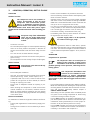
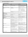
Explanation of the short operating instructions on the unit
Read instruction manual before
operating unit
chapter 3.
Check oil level on compressor and
petrol engine before operating
unit
chapter 4.4.1.
Drain condensate at least every 15
minutes (3 locations)
chapter 4.4.3. and 4.4.4.
Position units with petrol engine
with exhaust in wind direction to
prevent exhaust fumes being
sucked in by the compressor
chapter 3.
Petrol driven units must not be op
erated indoors.
chapter 3.
Position unit level: max. inclination
5
chapter 3.
Operate unit only at ambient tem
peratures between +5 and +45 C
chapter 3.
Keep away from hot surfaces on
motor and compressor
chapter 2.
Wear ear protectors when unit is
running
chapter 2.

Instruction Manual Junior II
iii
CONTENTS
1. GENERAL 1............................
2. SAFETY MEASURES 5....................
3. LOCATION, OPERATION, BOTTLE FILLING 9..
4. MAINTENANCE 17.......................
5. STORAGE, PRESERVATION 31..............
6. REPAIR INSTRUCTIONS 32.................
7. TABLES 33..............................
8. ANNEX 35..............................
INDEX
A
Adhesive chart, 34
Air flow diagram, 1
Annex, 35
B
B-Timer, 13
C
Change-over device, 12
Cooling system, 28
D
Design, 1
Drive system, 27
E
V-belt, tension meter, 27
Electrical system, 28
F
Filling procedure, 10
Filter system, 19
I
Intake filter, 18
Intermediate separator, 19
Intake air quality, 10
L
Location, 9
Lubrication, 17
Lubrication chart, 34
M
Maintenance, 17
Maintenance instructions, 17
Maintenance record, 17
Maintenance schedule, 17
Motor protection switch, 28
O
Oil change, 18
Oil level check, 17
Oil type, 17
Operation, 9
P
Preservation, 31
Pressure gauge, 24
Pressure-maintaining valve, 23
R
Repair instructions, 32
S
Safety valves, 24
Sealant chart, 34
Shut-down, 12
Storage, 31
T
Tables, 33
Technical data, 4
Telescopic intake tube, 18
Testing agents, 34
Tightening torque values, 33
Torque sequence, 33
Trouble-shooting, 29
V
Valves, 25
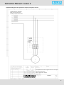
ANNEX
Schematic diagram motor protection switch, three phase current 76942-S1
Lubricating oil list 70851
Applicable parts list TJ-4/9

Instruction Manual Junior II
iv
NOTES
Model:
Serial No..:
Date of purchase:
Dealer address / phone no.:

1
3
8
4
6
5
7
2
9
Instruction Manual Junior II
1
1. GENERAL
PURPOSE
The JUNIOR II breathing air compressor is designed to
compress air for breathing as required in diving applica
tions. The max. allowable operating pressure (adjusted
pressure on final pressure safety valve) is 225 bar or 330 bar.
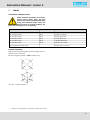
DESIGN
The compressor unit comprises the following major assem
blies:
- compressor block
- drive motor
- filter system P21
- filling assembly
- base plate and frame
The design of the compressor system is shown in Abb. 1 to
Abb. 4.
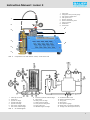
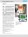
AIR FLOW DIAGRAM
See Abb. 5 . The air is drawn in through telescopic tube
(necessary for units with petrol engine) -1, intake filter -2;
compressed to final pressure in cylinders -3, -4, -5; recooled
by intercoolers -6, -7, and aftercooler -9. The pressures of
the single stages are protected by safety valves -10, -11,
-12. The compressed air is pre-cleaned in intermediate sep
arator -8 and purified in filter system P21 -13. Intermediate
separator and filter system P21 are drained by means of
condensate drain valves -15. Pressure maintaining valve -16
provides a constant pressure within the filter assembly. The
compressed, purified air is passed through filling hose -17
and filling valve -18 to the bottles to be filled. Filling pres
sure is indicated at pressure gauge -19. With the change
over device model it is possible to fill bottles with 200 bar
nominal pressure, just by opening valve -21 at filling valve
-18. Safety valve -20 is adjusted to a blow off pressure of
225 bar.
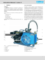
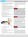
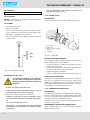
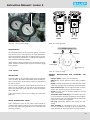
Abb. 1 Compressor unit with petrol engine
1 Filling hose
2 Exhaust
3 Air filter
4 Tank
5 Throttle lever
6 Choke lever
7 Fuel cock
8 Starter rope
9 Engine stop switch (ignition)
10 Filling valve with final pressure gauge
11 Safety valve, final pressure
12 Filter system P21
13 B-Timer
14 Condensate drain taps

Instruction Manual Junior II
2
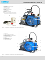
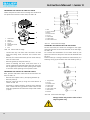
1 Filling hose
2 Filling valve with pressure gauge
3 Motor terminal box
4 Three-phase motor
5 Final pressure safety valve
6 Handle
7 Fanwheel cover
8 B-Timer
9 Condensate drain valves
10 Mains plug with ON-OFF switch and motor
protection circuit breaker (dep. on country)
1
2
4
3
10
Abb. 2 Compressor unit with electric motor (three-phase current)
1 Filling hose
2 Filling valve with pressure gauge
3 Motor terminal box with ON-OFF switch
4 Single-phase motor
5 Final pressure safety valve
6 Handle
7 Fanwheel cover
8 Pressure maintaining valve
9 Condensate drain valves
1
2
4
3
Abb. 3 Compressor unit with electric motor (alternating current)

Instruction Manual Junior II
3
1
2
4
3
7
8
5
9
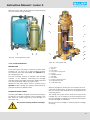
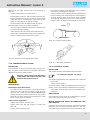
1 Filling hose
2 Filling valve with pressure gauge
3 Final pressure safety valve
4 Filter system P21
5 B-Timer (optional)
6 Pressure maintaining valve
7 Filling connector
8 Intake filter
9 V-belt cover
6
Abb. 4 Compressor unit with electric motor, v-belt cover side
8
11
15
2
1 Telescopic air intake
2 Intake filter
3 Cylinder 1st stage
4 Cylinder 2nd stage
5 Cylinder 3rd stage
6 Inter-cooler 1st/2nd stage
7 Inter-cooler 2nd/3rd stage
8 Intermed. separator 2nd/3rd stage
9 After-cooler
10 Safety valve 1st stage
11 Safety valve 2nd stage
12 Final pressure safety valve
13 Filter system P21
14 TRIPLEX longlife cartridge
15 Condensate drain valve
16 Pressure maintaining valve
17 Filling hose
18 Filling valve
19 Final pressure gauge
20 Safety valve, final pressure PN 200
21 Change over device (optional extra)
Abb. 5 Air flow diagram

Instruction Manual Junior II
4
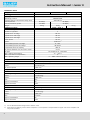
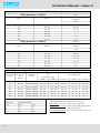
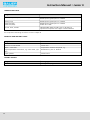
TECHNICAL DATA
Compressor unit JuniorII-B-F01 JuniorII-E JuniorII-W
Medium air
Delivery
a)
100 l/min. (3,5 Scfm)
Operating pressure PN200/PN300
Pressure setting, final pressure safety valve 225/330 bar
Sound pressure 87 dB(A) 86 dB(A)
Sound (immersion) power 100 dBA) 99 dB(A)
Weight 46 kg 44 kg 47 kg
Compressor block Junior, mod. 3
Number of stages 3
Number of cylinders 3
Cylinder bore 1st stage 60 mm
Cylinder bore 2nd stage 28 mm
Cylinder bore 3rd stage 12 mm
Piston stroke 24 mm
Speed 2,300 min
-1
Intermediate pressure 1st stage 6-7 bar
Intermediate pressure 2nd stage 40-60 bar
Compressor block oil capacity 360 ml
Oil volume between min. and max. marks 50 ml
Oil type see chapter 4.4.1. lubrication
Max. ambient temperature +5 ... +45 C
Max. inclination of compressor
b)
5
Max. operating height 0 ... 2000 m above sea level
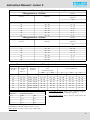
Compressor drive JuniorII-B
Drive motor Robin/Subaru petrol engine
Manual start model (B) EX17
Power 4.2 kW (5.7 PS)
at nominal speed 3,600 min
-1
Compressor drive JuniorII-E
Drive motor Three phase current
Operating voltage 400 V, 50 Hz
Power 2.2 kW (3 PS)
Speed 2,850 min
-1
Size 90 L
Type of construction B3
Type of enclosure IP54
Compressor drive JuniorII-W
Drive motor Alternating current
Operating voltage 230 V, 50 Hz
Power 2.2 kW (3 PS)
Speed 3,000 min
-1
Size LS 90 PC
Type of construction B3
Type of enclosure IP44
a) free air delivered at bottle filling from 0 to 200 bar "5%
b) these values are valid only if the oil of the compressor in normal position corresponds with the upper mark of the oil dipstick and
may not be exceeded.

MV3−A/10/06
WARNING
Instruction Manual Junior II
5
2. SAFETY MEASURES
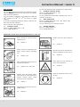
2.1. NOTES AND WARNING SIGNS
Notes and warning signs displayed on compressors accord
ing to model, application or equipment.
WARNING
Hot surfaces, do not touch!
Danger of burning by touching cylinders,
cylinder heads and pressure lines of indi
vidual compressor stages.
WARNING
High voltage!
Life threatening danger of electric shock.
Maintenance work on electric units or op
erating equipment may only be carried
out by a qualified electrician or by a per
son instructed and supervised by a quali
fied electrician according to electrical reg
ulations.
WARNING
Automatic compressor control, unit may
start-up without warning!
Before carrying out maintenance and re
pair work, switch off at the main switch or
disconnect from the mains and ensure
unit will not restart.
MANDATORY
Instructions must be read by persons op
erating the machinery!
The instruction manual supplied and all
other applicable instructions, regulations
etc. must be read and understood by op
erating personnel before using the ma
chine.
MANDATORY
Hearing protectors must be worn!
Hearing protectors must be worn when
working on a machine which is running.
NOTE
Ensure correct direction of rotation!
When switching on the machine, check
the arrow to ensure correct direction of
rotation of the drive motor.
2.2. IDENTIFYING THE SAFETY NOTICES
Important instructions concerning the endangerment of
personnel, technical safety and operating safety will be
specially emphasized by placing the following signs before
the instructions.
This notice is used with maintenance
work and operating procedures and
must be adhered to exactly in order to
avoid endangering personnel.
This notice must be complied with in order to
avoid damage to or destruction of the ma
chine or its equipment.
This notice advises of technical requirements
which the operator must take particular note
of.
2.3. FUNDAMENTAL SAFETY NOTICES
2.3.1. Authorized use
The machine / unit is built according to state of the art
technology and established safety technical regula
tions. Nevertheless, its use can cause danger to life and
limb of the operator or third parties or damage to the
machine and other equipment.
Operate the machine / unit only in technically perfect
condition in accordance with regulations and safety and
danger notices detailed in the instruction manual! In
particular, immediately correct faults (or have them cor
rected) which can impair safety!
The machine / unit is exclusively for the compression of
mediums (air/gas) specified in section A, chapter 1.3.
“Technical data”. Any other medium or use outside that
specified is not authorized. The manufacturer / supplier
is not liable for damage resulting from this. The user
alone is responsible for this risk. Authorization for use
is also under the condition that the instruction manual
is complied with and inspection and maintenance re
quirements are enforced.
2.3.2. Organizational measures
Keep the instruction manual to hand near the machine
/ unit at all times in the relevant holder.
In addition to the instruction manual, observe and com
ply with universally valid legal and other obligatory re
gulations regarding accident prevention and environ
ment protection. See chapter 2.4. This can involve, for
example, contact with hazardous substances or the
provision / wearing of personal protective equipment.
Personnel engaged to operate the machine must have
read the instruction manual before beginning work, es

Instruction Manual Junior II
6
pecially the safety notices chapter. When work is al
ready underway it is too late. This is particularly relevant
for temporary personnel, e.g. maintenance personnel.
Personnel may not wear long hair loose, loose clothing
or jewellery, including rings. There is a danger of injury
through, for example, these getting caught or being
pulled into the equipment.
As far as necessary or according to regulations, use per
sonal protective equipment.
Observe all safety and danger notices on the unit.
Keep all safety and danger notices on the machine / unit
complete and in readable condition.
If there are any modifications to the unit or operating
conditions which may affect safety, stop the unit im
mediately and inform the person responsible of the
fault.
No modifications may be made to the unit which could
impair safety without first obtaining permission from
the suppliers. This is also the case with regard to installa
tion and adjustment of safety devices and valves as well
as welding of piping and reservoirs.
Spare parts must always comply with the technical re
quirements specified by the manufacturer. This is always
guaranteed with original spare parts.
Piping must be thoroughly checked (pressure and visual
inspection) by the operator at appropriate time inter
vals, even if no safety related faults have been noticed.
Intervals stipulated or given in the instruction manual for
recurring checks / inspections must be adhered to.
Make sure location and operation of fire extinguishers
is known.
Pay attention to fire warning and fire fighting pro
cedures.
2.3.3. Qualifications, fundamental duties
Work on / with the unit may only be carried out by reli
able personnel. Observe the legal minimum age per
missible.
Ensure that only trained personnel work with the ma
chine.
Establish the responsibilities of the machine operator
and establish a procedure for him to inform a third per
son of unfavourable safety conditions.
People who are being trained or introduced to the job
should only be allowed to work with the unit under con
stant supervision of an experienced person.
Work on the electrical equipment of the unit may only
be carried out by a qualified electrician or by an in
structed person under the direction and supervision of
a qualified electrician according to electrotechnical re
gulations.
2.3.4. Safety notices for operation
Do not carry out any work if safety is questionable.
Meet all requirements demanding that the unit is only
operated in safe and good working order. Only operate
the machine if all protective and safety equipment, e.g.
all detachable protective equipment, emergency shut-
down devices, soundproofing is provided and in good
working order.
At least once every day, check the unit externally for
damage and faults. Inform the person responsible im
mediately if anything is not as is should be (including
operation). If necessary, shut the machine down im
mediately and make it safe.
Observe switching on and off processes and monitoring
indications according to the instruction manual.
Before switching on / starting up the unit, ensure that no
one can be put at risk through running the unit.
Carry out the setting, maintenance and inspection pro
cesses at the intervals specified in the instruction man
ual, including replacement of parts / equipment. This
work may only be carried out by qualified personnel.
Clear and make the maintenance area safe as far as
necessary.
If the unit is completely switched off for maintenance
and repairwork, ensure that it is protected from unex
pected start-up. Turn off main control device and re
move the key and / or display a warning sign on the main
switch.
When replacing individual parts and larger assembly
groups, they must be carefully fastened to the lifting de
vice so that there is no risk of danger. Use only suitable
and technically perfect lifting devices and equipment
with sufficient lifting power and strength. Do not linger
or work under suspended loads.
Only entrust an experienced person with the fixing of
loads and guiding of crane drivers. The person guiding
must remain within sight or in contact with the oper
ator.
For assembly work above body height, use appropriate
safety approved equipment, e.g. ladders and platforms.
Do not climb on machine parts. For maintenance work
at high levels, wear a safety harness.
Clean oil, fuel or care products from the machine, in par
ticular the connections and screw joints, before carrying
out maintenance / repairwork. Do not use aggressive
cleaning fluid. Use a fibre-free cleaning cloth.
Before cleaning the machine with water or jet of steam
(high pressure cleaner) or detergent, cover / seal all
openings which for safety and/or operating reasons no
water / steam / detergent may penetrate. Electric motor
and switch cabinets are particularly at risk.
When cleaning the operating room, ensure that the
temperature sensors of the fire alarm and sprinkler sys
tem do not come into contact with hot cleaning fluid,
in order to avoid triggering the sprinkler system.
Completely remove all covers / seals after cleaning.
After cleaning, check all pressure lines for leaks, loose
connections, wear and damage. Immediately eliminate
any faults.

Instruction Manual Junior II
7
Always retighten any screw connections loosened for
maintenance or repairwork.
If it is necessary to remove safety devices for mainten
ance and repairwork, these must be replaced and
checked immediately after completion of the mainten
ance or repairwork.
Ensure safe and environmentally friendly disposal of
consumables and old parts.
2.3.5. Particular areas of danger
Use only original fuses with specified current rating. If
there is a failure in the electric energy supply, shut the
unit down immediately.
Work on electric units or operating equipment may only
be carried out by a qualified electrician or by a person
under the instruction and supervision of a qualified elec
trician according to electric technical regulations.
Machines and unit parts which must undergo inspec
tion, maintenance and repairwork, must be discon
nected from the mains supply, if specified. Parts which
have been disconnected must first be checked for volt
age, then earthed and short-circuited and isolated from
live neighbouring parts.
The electrical equipment of a unit must be regularly
checked. Defects, such as loose screw connections or
burnt wires, must be rectified immediately.
If work is to be carried out on live parts, work with a sec
ond person who can operate the emergency off switch
or the main switch in the case of an emergency. Close
off the work area with a red and white safety chain and
a warning sign. Only use voltage isolated tools.
Only personnel with particular knowledge and experi
ence with pneumatics may carry out work on pneumatic
equipment.
Check all pressure lines, hoses and screw connections
regularly for leaks and visible damage. Immediately re
pair any damage. Escaping air under pressure can cause
injury and fire.
Depressurize system and pressure lines before com
mencing repairwork.
Pressurized air lines must be laid and mounted by quali
fied personnel. Connections must not be mixed up. Fit
tings, length and quality of the piping must correspond
to requirements.
Soundproofing equipment on the unit must be in place
and functional during operation.
The stipulated hearing protectors must be worn.
With regard to oil, grease and other chemical sub
stances, observe the relevant safety regulations for the
product.
For loading, only use lifting device and equipment with
sufficient lifting power and strength.
Use only suitable transporters with sufficient carrying
power. Secure the load properly. Use suitable fixing
points.
If necessary, provide unit with transportation brackets.
Display the appropriate notice. Remove transportation
brackets in the correct manner before taking into oper
ation.
Parts which need to be dismantled for transport pur
poses must be carefully replaced and secured before
taking into operation.
Even when moving the unit only slightly, the unit must
be disconnected from all external energy sources. Be
fore putting into use again, reconnect the machine to
the mains according to regulations.
When taking back into operation, proceed according to
the instruction manual.
2.3.6. Notices of danger regarding pressure vessels
Never open or loosen pressure vessel lids or pipe con
nection parts under pressure; always depressurise the
vessel or the unit.
Never exceed the permissible operating pressure of the
vessels!
Never heat the vessels or any of their parts above the
stated, maximum operating pressure.
Always exchange damaged pressure vessels com
pletely. Individual parts that are subject to pressure
loads cannot be purchased as spare parts, since the
vessels are tested as a complete part and the docu
mentation considers them as a whole (see pressure
vessel documentation, serial-numbers!).
Always pay attention to the permissible operating mode
of the pressure vessels.
We differentiate:
- vessels for static load
- vessels for dynamic load
Vessels for static load:
These pressure vessels are permanently under virtually
constant operating pressure; the fluctuations of pres
sure are very small.
Vessels for this type of load are not marked in a particu
lar way and may be used as long as the vessel inspec
tions, carried out regularly, do not uncover any safety-
relevant deficiencies.
We recommend that aluminium vessels should be
exchanged after 15 years at the latest.
Vessels for dynamic load:
These pressure vessels may also be used under condi
tions of changing operating pressure. The pressure may
vary between the atmospheric and the maximum ad
missible operating pressure.
The pressure vessel documentation and the appropriate
notes in the operating manual particularly characterise
vessels of this type as being adequate for dynamic loads.
In the technical information for these vessels you will
find specifications concerning their permissible operat
ing period.
Due to the variation of the operating pressure, these
vessels are subject to a so-called dynamic load, which

Instruction Manual Junior II
8
puts the vessels under great stress. The change between
two different pressures is called a load change or cycle.
In the technical information for these vessels you will
find specifications concerning the permissible number
of cycles depending on the fluctuation of the operating
pressure.
Having reached half the permissible number of cycles,
the vessel has to be submitted to an internal check, in
which the critically stressed areas of the vessels are
examined by means of suitable testing methods, in
order to ensure the operating safety.
After having reached the total permissible number of
load cycles, the vessel must be exchanged and
scrapped.
Record the number of load cycles in writing if you do not
have an automatic cycle-counter.
We recommend that aluminium vessels should be
exchanged after 15 years at the latest.
Please pay attention to and follow these measures, for
your own safety and that of you employees and cus
tomers!
In order not to unnecessarily load the pressure vessels
additionally, the non-return valves, that are meant to
avoid a drop in pressure, and also the pressure maintain
ing valves, which should reduce big pressure fluctu
ations as well, should be checked regularly for internal
and external tightness and functionality.
Check the pressure vessels regularly on the inside and
outside for damage from corrosion.
Be particularly careful with second-hand pressure
vessels, when their previous operating mode is not spe
cifically clarified.
2.4. SAFETY REGULATIONS (EC; partly Germany,
only)
A compressor is identified by German law as being a filling
system if pressure cylinders are filled by the system, es
pecially when these cylinders are made available for third
parties. The start-up and operation of compressor systems
for use as filling stations is governed by the following re
gulations:
Pressure vessel directive (Directive 97/23/EC) of
29.05.1997
Operating safety regulations (BetrSichV) of
27.09.2002
Machine safety law (GSG) of 11.05.2001
14th regulation to machine safety law (14. GSGV -
pressure vessel regulation) of 03.10.2002
Technical regulations for pressure gases (TRG 400,
401, 402, 730).
If a high pressure compressor is used for filling pressure
vessels or for the supply of pneumatic systems, the follow
ing regulations apply:
Accident Prevention Regulations (UVV):
BGV A1 of 01. January 2004
Copies of the above regulations are available through the
usual outlets, e.g. in Germany from:
Carl Heymanns Verlag
Luxemburger Str. 449
50939 Köln
Beuth-Vertrieb GmbH
Burggrafenstr. 4 - 7
10787 Berlin
The manufacturer has complied with all applicable regula
tions and the unit is prepared accordingly. If desired, we
offer at our Munich site a partial acceptance test according
to § 14 BetrSichV. Please contact our Technical Service De
partment with regard to this. They can also supply our
leaflet “IMPORTANT NOTES FOR CERTIFICATION”.
According to the operation safety regulations (BetrSichV),
all compressor units which will be used as filling stations
must undergo an acceptance test by a professional at their
location before bringing them into service. If pressure
vessels (bottles) are to be filled by the compressor for a third
party then the appropriate permission must be obtained
from the responsible authority before the acceptance test.
As a rule, this is the factory inspectorate. The procedure for
obtaining permission is according to TRG 730, guidelines
for permission to set up and operate filling stations. The test
certificates and documents delivered with the compressor
are important and may be requested during the procedure
for obtaining permission. In addition, the documents be
longing to the unit are important for recurrent inspections
and should therefore be carefully kept.
Inspections in accordance with the regulations for preven
tion of accidents will be carried out by the manufacturer or
by a specialist.
No guarantees whatsoever are valid for damage caused or
favoured by the non-consideration of these directions for
use.
We strongly emphasize these regulations.

WARNING
WARNING
WARNING
Instruction Manual Junior II
9
3. LOCATION, OPERATION, BOTTLE FILLING
LOCATION
Outdoor location
The compressor unit is not seawater re
sistant. At operation in salty air spray
compressor with anticorrosive protec
tion (e. g. Quicksilver Corrosion Guard).
Electric driven units should be operated
and stored below deck. Units with petrol engine
should also be stored below deck after the filling pro
cess.
Keep unit away from inflammable
items. Do not smoke while petrol
tank is open and while unit is in op
eration.
- Locate the unit level.
- On units with petrol engine it is most important that only
clean air be used, position compressor in direction of
wind so that exhaust fumes are blown away from the
unit.
- Turn unit as soon as wind direction changes.
- Take care that no vehicles are in direct vicinity with en
gines running.
- Do not operate unit in the vicinity of open fire (flue gas!).
Indoor location
Petrol driven units must not be op
erated indoors.
- Ensure adequate ventilation.
- Here too, air must be free from exhaust fumes and haz
ardous vapours (e.g. smoke, solvent vapours, etc.).
- If possible install unit in such a manner that the com
pressor fan can get fresh air from outside, for instance
through an opening in the wall.
- Ensure that an adequate exhaust air opening is pro
vided.
- When locating the compressor in small rooms where
natural ventilation is not ensured, measures must be
taken to provide artificial ventilation (this also applies
when other systems having high radiation are operating
in the same room).
Electrical installation
For installation of electrical equipment observe the follow
ing:
- Comply with regulations of local electricity supply com
pany.
- Arrange for the electrics to be connected by an electri
cian only.
- Ensure correct installation of protective conductor.
- Check conformity of motor tension and frequency with
those of electric network.
- Operate electric units only on mains sockets equipped
with fault current circuit breaker according to DIN VDE
0664 with a nominal differential current of less than 30
mA (up to 16 A in single-phase AC circuits).
- For units not connected through a plug, but perma
nently installed, a main switch must be provided which
has a contact gap of minimum 3 mm on each pole.
- Fuse motor correctly; use slow-blow fuses, only.
- Immediately after start-up check direction of rotation
for agreement with arrow on unit.
If power supply cable is to be replaced,
use cable of same type, only!
- When using extension leads or cable drums, operate
unit with unwound cable, only to avoid overheating and
risk of fire. The maximum length for extension cables at
normal ambient temperatures (approx. 20 C) is 25 me
tres.
OPERATION
Preparation for operation
All compressor units are tested prior to
delivery to the customer, so after correct
installation of the unit there should be no
problem putting it into operation, observing the fol
lowing points:
The compressors described in this
manual are not suitable for com
pression of oxygen. EXPLOSION
occurs if an oil lubricated compressor is operated with
pure oxygen or gases with an oxygen content of more
than 21%!
- Prior to first operation read Instruction Manual carefully.
Make sure that all persons handling the compressor and
the filling station are familiar with the function of all con
trols and monitors. Particularly observe chapter 2
SAFETY REGULATIONS.
- After taking unit into operation after a standstill period
of 2 years or more change compressor oil. When using
a mineral oil change oil after one year.
- Prior to first operation or operation subsequent to re
pair work operate unit for at least 5 minutes with open
condensate valves (pressureless) to ensure proper lu
brication of all parts before pressure is built up.
- Prior to each operation check the oil level according to
chapter 4.4.1. and determine whether maintenance is
necessary in accordance with chapter 4.3.

WARNING
WARNING
WARNING
Instruction Manual Junior II
10
- Every time the unit is started up check all systems for
proper operation. If any malfunction is observed stop
unit immediately and find the cause of the fault or call
the service department.
Units with three phase current motor, additionally:
- Immediately after switching on the system for the first
time check the direction of rotation of the motor for
compliance with the arrow on the unit. If motor turns in
the wrong direction, the phases are not connected
properly. Shut down unit immediately and interchange
two of the three phase leads in the switch box. Never
change leads at the motor terminal board.
Units with petrol engine, additionally:
- Check engine oil level according to manufacturer's in
struction manual.
- Check fuel tank. Top up if necessary.
- Open fuel shut-off valve.
Starting the unit (electric and petrol)
- Open condensate drain valves on the filters to release
pressure so that motor starts without load.
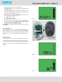
Units with electric drive motor:
- Three-phase current: the motor is switched on man
ually by turning the switch (1, Abb. 6) to 1.
Abb. 6 Motor protection switches
(three-phase motor)
1
- Alternating current: Set 0-I switch to I.
Units with petrol engine:
- Set choke to position START. Start engine with recoil
starter or crank handle. As soon as motor runs smoothly
return choke to normal operating position.
All units (electric and petrol):
- Close condensate drain valves and run unit to final pres
sure. Check final pressure safety valve and pressure
gauge.
- As soon as final pressure is reached and final pressure
safety valve blows off, open condensate drain valves
and drain condensate - unit is ready for filling operation.
Observe regular condensate drain acc. to chapter
“Maintenance”.
FILLING PROCEDURE
General
Ensure intake air is free from
noxious gas (CO), exhaust fumes
and solvent vapour. On units em
ploying petrol or diesel engine it is most important to
use an intake hose and observe that only clean air is
drawn in. The intake hose is also recommended for
units with electric engine. When operating the unit in
areas with possibly high CO contents, the CO removal
filter cartridge is recommended for electric driven
units, also. Note that for CO contents of more than 25
ppmV in the intake air the allowed limits cannot be
guaranteed even with a CO removal filter cartridge,
resulting in a life-threatening CO concentration! Also,
due to chemical reaction of CO with hopcalite, warm
ing up of the cartridge and danger of fire may result.
Filling hoses must be in satisfac
tory condition and threads undam
aged. Pay particular attention to
damage on the interface from hose fitting to hose. If
the casing is scored, hose must be discarded.
The filling valve connection is of the manual type and per
mits connection to air tanks without using tools. An O-ring
is provided for self-sealing due to internal overpressure.
Compressed air tank filling valves for a pressure in excess of
200 bar are standardized (DIN 477, sheet 5) and connectors
for 200 and 300 bar are different and cannot be mixed up.
The use of adapters is not allowed!
To ensure safe air tank removal after filling, the valve has an
integral venting bore. Therefore always close tank valve
first before closing filling valve. During filling procedure
bottles will warm up due to recompression. After removing,
allow to cool down, bottles may then be reconnected and
topped up to the respective maximum filling pressure.
To meet the CO
2
maximum rating
value in breathing air bottles,
please observe the two following
chapters ”Intake air quality” and ”Scavenging the
compressor unit”.
Intake air quality
At routine tests, CO
2
values beyond the permissible values
are noted from time to time. Closer investigations often
show that the compressed air is taken from rooms in which
one or more persons are working. At insufficient ventila
tion, the CO
2
value in the surrounding air can increase quite
fast because of the exhaling of CO
2.
CO
2
values from 1,000
to 5,000 ppmv in workrooms are not unusual (MAK-value
(max. workroom concentration) is 5,000 ppmv). Another

Instruction Manual Junior II
11
additional increase is caused by cigarette smoking, produc
ing approx. 2g CO
2
( 2,000 ppmv) per cigarette. These
pollutions add up to the basic pollution of approx. 400
ppmv. The technically caused excessive increase of CO
2
during the filling process and the CO
2
peak at taking the
unit into operation. Because of the reasons stated
above and for your own security, the filling of breath
ing air bottles is not allowed in rooms used as work
rooms.
Scavenging the compressor unit
CO
2
is present in the atmosphere with a natural amount of
350 to 400 ppm
V
. The molecular sieve used in the purifier
for drying the breathing air is, as well as other capabilities,
able to adsorb CO
2
which is accumulated in the cartridge.
After shut-down of the compressor, adsorbed CO
2
may be
desorbed again due to the partial pressure decrease. The
now free CO
2
then gets washed out of the cartridge when
the compressor is started again. To avoid increased CO
2
contents in the compressed breathing air, we recommend
to flush the compressor unit 1 to 2 minutes prior to connect
ing the bottles, i.e. to let the air escape into the surround
ings through the filling valve.
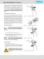
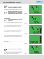
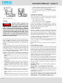
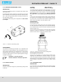
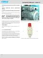
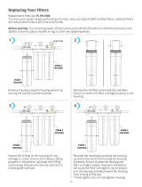
Connecting the bottles
On models of 300 bar rated filling pres
sure do not attach bottles unless rated for
this pressure (note pressure stamped on
tank neck).
- Connect air bottle to filling valve (see Abb. 7).
- Air bottles with international filling connector can be
connected with filling adaptor (part no. 79375) to the
German filling connector (see Abb. 8).
The international connector is not per
mitted in the Federal Republic of Ger
many. In other countries it is allowed only
for pressures up to 200 bar (2,850 psi).
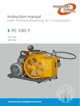
Filling the bottles
- Open filling valve (1, Abb. 9).
- Open bottle valve (2) - bottle will be filled. Drain conden
sate regularly during filling. On units with automatic
condensate drain check that condensate is drained reg
ularly.
The filling procedure should not be inter
rupted for more than 10 minutes to avoid
increased CO
2
-values in the air filled into
the bottles.
Abb. 7 Connecting air bottle
Abb. 8 International filling connector
2.
1.
Abb. 9 Filling air bottle
Abb. 10 Removing air bottle
2.
1.

Instruction Manual Junior II
12
Removing the bottles
- Upon reaching final bottle pressure close bottle valve
first (1, Abb. 10), then filling valve by returning
handle to closed position (2).
- Remove compressed air bottle.
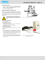
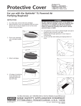
CHANGE-OVER DEVICE PN 300/PN 200
(Abb. 11) This device allows bottle filling to 200 bar
(3,200 psig) with a 300 bar (4,700 psig) rated unit. Safety
valve -B and filling device PN 200 bar are connected by
opening change-over valve -A and the connected bottles
can be filled with a 200 bar pressure, as described in ”Filling
the bottles”.
Depressurize unit before opening valve -A
to avoid damage to the change-over de
vice
SHUT-DOWN PROCEDURE
- Close filling valve.
Units with electric motor:
- Three-phase current: the motor is switched off by
turning the switch (1, Abb. 12) to 0.
- Alternating current: set 0 - I switch to 0.
Units with petrol engine:
- Shut down petrol engine with stop button or stop lever.
All units:
- Drain condensate from intermediate separator and
Triplex filter by means of the drain taps. Vent unit by
means of filling valve to approx. 80 bar (1,150 psi). Close
all valves again to prevent moisture entering the filter
and resulting saturation of the cartridge.
- Check the oil level in the compressor and top up, if
necessary. Also check whether the compressor needs
servicing in accordance with maintenance schedule -
see chapter 4.3.
Abb. 11 Change-over device
B
A
Abb. 12 Motor protection switches
(three-phase motor)
1

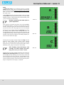
Abb. 13 B-Timer
1 Key symbol (maintenance due)
2 Letter symbol (maintenance type)
3 Low battery symbol
4 Cartridge saturation indicator
5 Operating hours or cartridge number
6 Mode select key
7 Enter key
1
2
3
4
5
6 7
Instruction Manual Junior II
13
B-TIMER (optional)
Introduction
Read operating instructions carefully before operating the
unit.
The settings in the setup menu are essen
tial for the correct indication of the filter
capacity. Without correct settings, the B-
Timer can be used as an hourmeter, only!
Make sure that the pressure maintaining
valve of the compressor is adjusted to
150 bar (factory setting, see chapter
4.4.5.) and is working properly to ensure correct in
dication of the filter capacity and compressor oper
ation recognition.
Make sure that all maintenance counter
(a+b+c) were reset directly before the
delivery. (Otherwise storage times would
be taken into account and wrong maintenance in
tervals are displayed on the B-Timer.) If no reset of the
maintenance counters has been done, you are obliged
to reset them. Refer to chapter Reset.
Description
The B-Timer (Abb. 13) is a self-activating mini-computer
that counts the operating hours of the compressor and
calculates the saturation of the filter cartridge from time,
temperature, cartridge type, and delivery rate of the com
pressor. It displays operating hours, cartridge lifetime, and
all maintenance due for the compressor. The B-Timer does
neither need external power nor any other connection to
the pressure system. It is simply fastened to the filter hous
ing which has to be monitored, by means of a clamp, and
is therefore the ideal filter control device for all mobile com
pressor units, especially for portable petrol or diesel driven
scuba diving models. In addition, the B-Timer can be
mounted easily to any unit as an upgrade device.
Authorized use
This unit is to be used exclusively as operating status moni
toring device and does not release the user from additional
surveillance and testing of the breathing air quality of the
filter system according to national standards (e.g. EN
12021). With the B-Timer, this is not possible!
The B-Timer may only be used with the filter systems P21,
P31 and P41. The respective filter cartridge numbers are
stored in the software. Other use is strictly prohibited. The
manufacturer and the supplier void all responsibility for risk,
damage or injury resulting from failure to follow these
instructions.
Please observe the operating limits of the unit:
Operating temperature range 0 C to +50 C,
Storage temperature -20 C bis +70 C
Protection class IP65 (Protection against contact with wire,
dust, and jet of water
Vibration $3g in operation
max. 95% humidity, not condensating
Function
The B-Timer display shows the following functions:

Abb. 14
Abb. 15 Battery
Abb. 16
Abb. 17
1
2
Instruction Manual Junior II
14
Operating hours of the compressor unit
Cartridge lifetime in % by means of four segments in the
cartridge symbol.
Flashing last segment and change from operating hours
indication to cartridge part no. if capacity is equal or less
than 20% of the original lifetime.
Indication of compressor maintenance due by means of
letter symbols and operating hours.
A = 500 hours or 1 year
B = 1000 hours or 2 years
C = 2000 hours or 4 years
Battery symbol indicating that the lithium battery is low
and has to be changed. All data are stored and will
not be lost when changing battery.
The B-Timer is operated using the mode select and the
enter keys.
Error indication
If the temperature sensor in the unit should be defective, an
error message “Error 1” or “Error 2” is shown at the display
(Abb. 14). In this case the unit should not be used but sent
to the factory or the nearest BAUER representative for re
pair.
Battery change
The battery (1, Abb. 15) is merely inserted into the holder.
To change the battery remove two bolts and separate hou
sing from base plate. Remove plug (2) and pull out battery.
Make sure to use the same type battery (BAUER part no.
82743).
Page is loading ...
Page is loading ...
Page is loading ...
Page is loading ...
Page is loading ...
Page is loading ...
Page is loading ...
Page is loading ...
Page is loading ...
Page is loading ...
Page is loading ...
Page is loading ...
Page is loading ...
Page is loading ...
Page is loading ...
Page is loading ...
Page is loading ...
Page is loading ...
Page is loading ...
Page is loading ...
Page is loading ...
Page is loading ...
Page is loading ...
Page is loading ...
Page is loading ...
Page is loading ...
-
 1
1
-
 2
2
-
 3
3
-
 4
4
-
 5
5
-
 6
6
-
 7
7
-
 8
8
-
 9
9
-
 10
10
-
 11
11
-
 12
12
-
 13
13
-
 14
14
-
 15
15
-
 16
16
-
 17
17
-
 18
18
-
 19
19
-
 20
20
-
 21
21
-
 22
22
-
 23
23
-
 24
24
-
 25
25
-
 26
26
-
 27
27
-
 28
28
-
 29
29
-
 30
30
-
 31
31
-
 32
32
-
 33
33
-
 34
34
-
 35
35
-
 36
36
-
 37
37
-
 38
38
-
 39
39
-
 40
40
-
 41
41
-
 42
42
-
 43
43
-
 44
44
-
 45
45
-
 46
46


Bauer Junior II-W User manual
- Type
- User manual
- This manual is also suitable for
Ask a question and I''ll find the answer in the document
Finding information in a document is now easier with AI
Related papers
-
Bauer mariner 320 User manual
-
-
-
Bauer NE User manual
-
-
Bauer Magnum S Operating instructions
-
-
-
-
Other documents
-
 Geozon JUNIOR User manual
-
 PRO+AQUA FC-PK-100E User manual
-
 POSEIDON PE 100-T User manual
-
 Hessaire 6020081 Installation guide
-
EINHELL 4020505 Datasheet
-
 OptimAir TL PAPR Owner's manual
-
California Air Tools EZ-1-2301 User manual
-
-
Parkside PKO 500 A1 Operation and Safety Notes
-


