Xpelair AirLine LED ALL100T User manual

Type
User manual

This manual is also suitable for

AXIAL F ANS
user manual
www.xpelair.co.uk
EN
AirLine
AirLine LED
2
WARNING!
!
Recycle at the end of the service life.
Do not dispose the product with unsorted municipal trash.
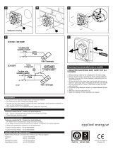
Disconnect the fan from power mains prior to any connection, servicing and repair operations. Mounting and
maintenance are allowed for duly qualified electricians with valid electrical work permit for electric operations at
the units up to 1000 V after careful study of the present user
s manual.
The single-phase power mains must comply with the acting local electrical norms and standards.
The fixed electrical wiring must be equipped with an automatic circuit breaker. The fan must be connected to
power mains through an automatic circuit breaker
F integrated into the fixed wiring system with the gap
between the breaker contacts on all poles not less than 3 mm.
heck the fan for any visible damages of the impeller and the casing before starting installation. The casing
internals must be free of any foreign objects which can damage the impeller blades. Misuse of the device or any
unauthorized modification is not allowed.
The fan is not to be used by children and persons with reduced physical, mental or sensory capacities, without
proper practical experience or expertise, unless they are controlled or instructed on the product oper
ation by the
person(s) responsible for their safety. Do not leave children unattended and do not let them play with the
product.
Take steps to prevent ingress of smoke, carbon monoxide and other combustion products into the room through
open chimney flues or other fire-protection devices. Sufficient air supply must be provided for proper
combustion and exhaust of gases through the chimney of fuel burning equipment to prevent back drafting.
Transported medium must not co
ntain any dust or other solid impurities, sticky substances or fibrous materials.
Do not use the fan in the environment containing hazardous or explosive materials and vapours, i.e. spirits,
gasoline, insecticides, etc.
Do not close or block the fan intake or extract vents in order to ensure the most effective air passage. Do not sit
on the fan and do not put objects on it. Fulfill the requirements stated in this user
s manual to ensure long service
life of the product.
3
Xpelair X X
Fan series - AirLine AL100, AirLine LED ALL100
Extra options:
T - turn-off delay timer (only for AL100T & ALL100T)
Designation key example:
AirLine AL100T - fan with inlet spigot diameter 100 mm, AirLine series, equipped with a fixing
bracket and a turn-off delay timer.
FAN DESIGNATION KEY
EN
4
Read the present user manual carefully befor e proceeding with installation works.
Compliance with the manual r
ements ensures reliable operation and long service
life of the pr oduct. Keep the user's manual available as long as you use the product.
You may need to re-read the information on the product servicing.
DELIVERY SET
The delivery set:
1. Fan - 1 item;
2. Screws and rawl plugs (only for the models with the fixing bracket) - 4 items;
3. Plastic screwdriver - 1 item (only for the models with a timer);
4. Sealer - 2 items;
5. User manual;
6. Packing box.
BRIEF DESCRIPTION
The product described herein is an axial fan for supply and exhaust ventilation of small and medium-sized
premises. The fan is made of white plastic. The fan is designed for connection to
100mm air ducts.
Due to constant improvements the design of some models may slightly differ from those ones described in
this manual.
OPERATION GUIDELINES
The fan is designed for connection to AC 220-240 V, 50 Hz power mains.
The fan is designed for continuous oper ation always
dir
connected to power mains. Air flow
ection in the system must match the pointer direction on the fan casing.
Ingress protection rating against access to hazardous parts and water ingress - IPX4.
The fan is rated for operation at the ambient temperature ranging fr om +1 °C up to +45 °C.
EN
The fan is designed for vertical or horizontal installation inside the round air duct of respective diameter ,
fig. 1.
Fan mounting sequence:
Step 1 - Disconnect power supply. Fig. 2;
Step 2 - Mark and drill holes for fastening of the fixing bracket, install the fan. Fig. 3-5.
Step 3 - Remove the electrical cover on the fan terminal box (wired to the fan) and on the
Light terminal box (if applicable). Remove cable clamps. Fig 6-7.
Step 4 - Connect the mains supply to the terminal block in the terminal box(es) as shown in the wiring
diagrams. Re-install cable clamp. For Timer setting adjustment on Timer models, the electrical compartment
cover on the fan will need to be removed to access the timer adjustment. Fig 8-10.
Step 5 - Re-fit electrical covers to both fan and terminal box (as required).
Step 6 - connect air ducts of r
Step 7 - Cut a 100mm diameter hole in the ceiling in the appropriate position for the internal grille - ensure
the hole lies between roof joists. Fix internal grille/fan light to ceiling using appropriate fastenings.
Step 8 - Cut a hole to suit the External Grille in the required position. Fit using appropriate fastenings.
Step 9 - Connect air ducts to internal and external grilles and secure with cable ties supplied.
Step 10 - For LED versions remove the electrical cover on the LED Driver terminal box (wired to fan).
Remove cable clamp and wire according to wiring diagrams Fig. 8-9. Re-install cable clamp and re-fit
electrical cover.
Step 11 - Connect the fan to the power mains. Fig.14
espective diameter on both sides of the fan. Fig. 13.
L - Live
N - Neutral
~ - power mains
L
- timer contr ol line
QF - automatic circuit br eaker
S - external switch
ELECTRONICS OPERATING LOGIC
The fan with the timer T - the fan starts after the external switch, e.g. the light switch, supplies control
voltage to the input terminal L T (ST). After the control voltage is off, the fan continues operating within the set
time period adjustable from 2 to 30 minutes by the timer.
5
EN
6
To adjust the fan turn-off delay time, turn the control knob T clockwise to increase and counter-clockwise to
decrease the turn-off delay time respectively, fig. 10.
Warning!
MAINTENANCE
The fan maintenance periodicity is at least once per 6 months. Maintenance sequence:
- disconnect power supply, fig. 15;
- remove air ducts, fig. 16;
- clean the fan with a soft cloth and a brush wetted in mild detergent water solution;
- wipe the fan surfaces dry;
- connect the air ducts to the fan, fig. 19;
- connect the fan to power mains, fig. 20.
WARNING!
void water dripping on the electric components.
TRANSPORTATION AND STORAGE RULES
Transport the pr oduct by any tr ansportation vehicle in the manufactur
e the
delivered product in the manufactur
emise with the temperature
0 0
range fr age environment must not
contain dust, acid or alkali vapours that may cause corrosion of the product parts.
EN
Guarantee
UK only:
We, Redring Xpelair Group Limited, provide a guarantee against faulty parts and manufacture for a
period of 2 years, from the date of purchase. In the unlikely event of a product breakdown during
the guarantee period, please call our technical helpline on 0844 372 7766 for advice and assistance.
Exclusions:
- This guarantee does not cover compensation for the loss of the product or consequential loss of any kind
- Damage or defects to the product arising from incorrect installation or lack of maintenance
- Transportation costs
This guarantee does not affect your statutory rights.
Technical Advice and Service
Customers outside UK - see International below
UK: Xpelair have a comprehensive range of services including:
- Free technical advice help-desk from Engineers on all aspects of ventilation
- Free design service, quotations and site surveys
- Service and maintenance contracts to suit all requirements
Contact us for details:
- By telephone on Techline: +44 (0) 844 372 7766
- By fax on Techfax: +44 (0) 844 372 7767
- At the address below
Head Office, UK Sales Office and Spares
Redring Xpelair Group Ltd, Newcombe House, Newcombe Way, Orton Southgate, Peterborough, PE2 6SE, England.
Telephone: +44 (0) 844 372 7761
Fax: +44 (0) 844 372 7762
Sales/Spares Hotline: +44 (0) 844 372 7750
Sales/Spares Faxline: +44 (0) 844 372 7760
www.xpelair.co.uk
International:
- Guarantee: Contact your local distributor or Xpelair direct for details
- Technical Advice and Service: Contact your local Xpelair distributor
7
EN
8
1
9
L N
2
3
4 5
6 7
T
10
8
9
10
11
12
13
14
14
QF
15
16
17
18
19 20
MAINTENANCE
Approval mark
Manufacturing date
Sold
(name and stamp of the
trade company)
Date of sale
15
Acceptance ce rtificate
www.xpelair.com
The fan is duly rec ognized as serviceable.
AirLine AL100
Xpelair
Newcombe House
Newcombe Way
Orton Southgate
Peterborough
PE2 6SE
Standard
TimerAirLine LED ALL100
  • Page 1 1
  • Page 2 2
  • Page 3 3
  • Page 4 4
  • Page 5 5
  • Page 6 6
  • Page 7 7
  • Page 8 8
  • Page 9 9
  • Page 10 10
  • Page 11 11
  • Page 12 12
  • Page 13 13
  • Page 14 14

Xpelair AirLine LED ALL100T User manual

Type
User manual
This manual is also suitable for

Ask a question and I''ll find the answer in the document

Finding information in a document is now easier with AI