Page is loading ...

Troubleshooting Guide
Keypad is working properly when LEDs
Technical and Sales Assistance
If
you need assistance, call the toll-free Lutron
Technical
Support
Center. Please provide exact
model number when calling.
(800) 523-9466 (U.S.A
.•
Canada and the Caribbean)
Other countries call:
Tel: (610) 282-3800
Fax: (610) 282-3090
Visit our Web site at www.lutron.com
Lutroo
ElectroniCS
Co~,
Inc.
7200
Suter
Road
Coopersburg,
PA
18036-1299
LUTRON®
the
U.S~A.
4103
PIN
043-101
Rev.
B
up and loads respond as buttons are pressed.
LIMITED WARRANTY
lutmn
will, at its option, repair
or
rep~ace
any unit that
IS
defective
1n
materials
or
manufac~
tura within two years after purchase. For warranty service, relurn unit
to
place of purcha.se or
mail
10
Lulron at 7200 Suler
Rd~,
Coopersburg, PA 18036·1299,
Ihe Lutron Technical Supoort Cenler loll free at
800-523-94<16~
til eight years after the purchase.
Lutron
representative.
THIS WARRANTY
IS
IN LIEU OF
ALL
OTHER EXPRESS WARRANTIES, AND THE
·1MPlJEI)-WARAANTY
OF
MERCWAN1:
A
IiILITV-lS-LlMlTED
W-:rwo¥EARS~ROM~-UR.
CHASE.
THIS
WARRANTY
DOES
NOT
COVER
THE
COST
OF
INSTALLATION,
REMOVAL OR REINSTALLATION, OR
DAMAGE
RESULTING FROM MISUSE, ABUSE.
OR IMPROPER OR INCORRECT REPAIR, OR DAMAGE FROM IMPROPER WIRING
OR
INSTALLATION. THIS WARRANTY DOES NOT COVER INCIDENTAL OR CONSEQUEN·
TIAL
DAMAGES. LUTRON'S LIABILITY ON
ANY
CLAIM FOR DAMAGES ARISING OUT
OF
OR IN CONNECTION WITH THE MANUFACTURE, SALE, INSTALLATION, DELIVERY,
OR
USE OF
THE
UNIT
SHALL
NEVER EXCEED
THE
PURCHASE PRICE OF
THE
UNIT.
This warranty gives
legal rights, and you
may
also have other
from slate to state.
SO
the above limilalion may
nol
..
tatlon of incidental
or
consequential
to
you~
product
may
be
covered by one
or
more of Ihe fallowing U.S. patents: 4.835,343;
D436.930; 0453.742; 0456.783; 0461.782; 0465,460; 0465,770; 0466,090;
04<16.091;
0466,484 and corresponding foreign palents. U.S. and loraign palenls
pending~
Lutron,
Claro
l
and HomeWorks are registered trademarks and Satin Colors and seeTouch are
trade~
marks of Lulron Electronics
Co"
Inc.
(I;)
2003 Lutron Electronics Co
.•
Inc~
-~
~HOMEW
KS
-®
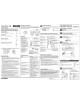
Installation Instructions
Please Read Before Installing
Overview
The STWO-1
B,
-2B, -3B, -3BRL, -4B, -4FS, -4S, -4SIR,
-5B, -5FS, -5BRL, -6B, -6BRL, and -7B keypads are for
use with
Home Works systems. The keypad buttons
are programmed with a personal computer using the
HomeWorks Utility.
to 32 keypads, each with a unique address, may
be connected to each keypad link on the HomeWorks
processor. A maximum of 300 LEOs may be connect-
ed per processor. Each see
Touch
keypad counts as
15 LEDs. To add capacity beyond 300 LEOs, refer to
the section about the HWI-PS
in
the HomeWorks
Technical Reference Guide (PIN 366-963).
Important Notes
Codes: Install
in
accordance with all local and nation-
al
electrical codes.
Environment:
Ambient operating temperature:
0-40°C, 32-104°F, 0-90% humidity, non-condensing.
Indoor use
Wallplates:
Lutron®
Claro®
and Satin
CoiorsTM
wall plates are recommended for best color match and
aesthetic appearance.
00
not paint controls or
wallplates.
Cleaning: To clean, wipe with a clean damp cloth.
DO NOT use any chemical cleaning solutions.
Wallboxes: Lutron recommends using 3 1/2 in.
(89mm) deep wall boxes for easier installation.
Keypad
Wiring:
Keypad wiring may
be
in a daisy-
chain, star
or
t-tap configuration. Each home run
on
a
link may be up to 1,000 ft. (305m) and may contain up
to 10 keypad devices. The total length of wire on that
link (all home runs) may be up to 4,000
ft.
(1220m).
tJini.T3Z~l<eypa:EraWrces-may
be-praM'<t<:irr-ea.cl1·~·
processor link configured as a keypad link
in
the
HomeWorks Utility. An external power supply may be
required depending
on
the total current draw of all
keypad devices on the processor.
LUTRON®
Designer-style Wired
seeTouchTM
Keypads
STWD·1
B,
·2B,
-3B,
-3BRl,
4B,
4FS,
4S,
4SIR,
-5B,
·5FS,
·58Rl,
·68,
-68Rl,
·7B
15 V ;:::,
77
mA
Class 2/PEL V
STWD-2B'
STWO-3B'
STWD·3BRL'
STWD-4FS'
STWD·4S' STWD-4SIR'
STWD·5B· STWD-5FS'
STWD-5BRL'
STWD-6B'
'I
~l
§
.c:=J
~J
I
STWD·6BRL'
STWD-7B'
• WaliplatelAdapter purchased separately.
Symptom
Cause and
Action
-----------
LEDs don't light up when buttons are pushed.
Power is not present
at
keypad.
• Make sure HomeWorks® processor
is
powered~
• Check for 15 VOC between pins 1 & 2 on the keypad connec-
tor.
• Remove connector from back
of
keypad, check connections
and replace.
• Check the HomeWorks Utility to make sure the keypad
is
pro-
grammed and addressed
correctly~
LEOs cycle from top
to
bottom sequentially.
Keypad is properly powered but is not communicating with the
processor.
• Verify that the processor is powered.
• Check that keypad wires
3 & 4 are properly connected.
• Check that keypad link
is
plugged into correct connector at
processor.
• Verify that link is configured for HWI keypads
in
the
HomeWorks Utility.
LEOs light when pressed, but the system response isn't correct.
• Check keypad for proper address.
• Check system programming.
1

Installation
1. Disconnect power to the keypads by turning OFF all
circuit breakers connected
to
the HomeWorks®
Processor
or
keypad link auxiliary power
[~ ~I
WI,lng with
pow.,
ON
may
,esuh
In
, personal injury.
•
2. Remove currently installed button kit (if applicable).
Remove button kit from keypad by gently prying it
from the top. See Button Kit Removal.
3.
Address keypads. Assign a unique address
to
each
keypad using the DIP switch settings.
See
Keypad
Addressing for DIP switch location and switch set-
tings.
Be
sure
to
record the address for future pro-
gramming purposes. Replace Button
Kit.
4. Strip insulation
to
3/8
in.
(1Omm).
5.
Unplug keypad link terminal block from the keypad
circuit board.
6. Connect wiring to terminal block as shown
in
Wiring
Diagram (page
3).
Each terminal will accept one
or
two #18 AWG
(1.0mm2)
wires.
7. Plug the keypad link terminal block back onto the
keypad circuit board.
Be
sure to orient the terminal
block correctly.
8. Connect external input closures (if applicable). All
seeTouchTM
keypads accept two low-voltage dry con-
tact closures (see Wiring Diagram - page 3).
When using the input closures:
Verify compatibility of external devices. The input clo-
sures are intended for use with devices that provide
outputs
in
the form of dry contact closure outputs.
The input closures may
be
used with ground-refer-
enced, solid-state outputs if the outputs have an on-
Button Kit Removal
state saturation voltage
of
less than 2 VDC and an
off-state leakage of less than 50
f.lA.
Dry contact or
solid-state outputs must be capable
of
switching
15 VDC at 10
mAo
The outputs must stay in the
closed
or
open states for at least 40 msec in order
to
be recognized
by
the keypad. If there is any
as to whether the contact closure device is compati-
ble with these specifications, contact the manufactur-
er
of
that device.
9. Push all wires back into the waJlbox and loosely fas-
ten the control
to
the wall box using the screws pro-
vided. Do not pinch the wires. See Mounting
Diagram.
10. Attach
Lutron®
Claro®
or
Satin
CoiorsTM
waJlplate
adapter and wailplate.
a.
Loosely install keypad mounting screws.
b.
Tighten wallplate adapter mounting screws
snug.
C. Tighten keypad mounting screws until
wallplate adapter is flush
to
wall (do not over-
tighten).
d.
Snap wall plate onto wall plate adapter, and
verify button kit is not submerged.
e.
If button kit is submerged, loosen
screws
",nnmnri;:,tAI
11. Restore power.
Mounting Diagram
Keypad
Adapter
Mounting Button
Keypad Addressing
Keypad
Front
View
DIP
Switches
(wallplate, wallplate adapter, and Set DIP switches 1-5 to give the keypad a unique HomeWorks® system address from 1 to 32.
button kit removed)
Address Address
Address
Address
# Switch
Satti""s
# Switch Settings
# Switch Settings # Switch Senings
1
!'jnn~e~~~1
9
!'j~nnen~1
17
~~~~nnHJ
25
~'~~~~~~~~I
2
!'j~~~,~e~~~1
10
!'j~~~nen~1
18
~'~~~~~nnl
26
~n~ne~nl
3
!'j~nnn~~1
11
~hnnnni
19
~n,,~en~1
27
~n~nn~~1
4
!'j~~~nen~1
12
~n'~~~n~1
20
~~"nnni
28
~~~"nn~1
5
~~~ne~n~~1
13
~ijnn~n~1
21
~~ne~e~nl
29
~n"nn~1
6
~.~nnn~~1
14
!'j~~~~nn~1
22
l!tun~nnl
30
~n~n~n~1
7
~~e~~n~~nl
15
~~~~nnni
23
~~nnnni
31
~'nnnni
8
~~e~~~~~~~~1
16
~~~~~~~~~~I
24
~~n~~eee~1
32
~~~~~ee~e~1
address.
Example: Setting Switch
#1
ON.
...-----UP
(ON)
...--
__
DOWN (OFF)
Wiring Diagram
HomeWorks Wired Processor
Bunon 20
Bunon 19
~
lim
Class 2/PELV wiring connections
from customer supplied contact clo-
Keypads can be connected to
any of these links depending
on the configuration
of
the
HomeWorks Utility.
_,----,_-,
---~~--~-
·-"··--~s·ure
devices.
1.
SWitch inputs must
be
momentary
dry contact closures.
2.
SWitch closures must be from com-
mon
to
selected
input
3. Momentary switch inputs require a
minimum closure time
of 40msec.
Pins 1 & 2
-1
pair #18 AWG (1.0mm') for power.
Pins 3
& 4
-1
pair #22-18 AWG (0.5 - LOmm')
twisted/shielded for data. Lutron$ wire, model #GRX-CBL-
346S-500, may be used.
LUTRON®
Screws Kit
Wallbox
Keypad
Mounting
Screws
LUTRON~
2
3
/