Page is loading ...

THIS INSTRUCTION BOOKLET CONTAINS IMPORTANT SAFETY INFORMATION.
PLEASE READ AND KEEP FOR FUTURE REFERENCE.
Date 2018-07-10 Rev. 0001-B Factory: KONRIC
Ellis Shutter Bookcase Cabinet
Stock # BH48-084-099-12
ADULT ASSEMBLY REQUIRED
If you have any questions regarding assembly or if parts are missing, DO NOT return this item to the
store where it was purchased. Please call our customer service number and have your instructions
and parts list ready to provide the model name, part name or factory number:
866-942-5362
Pacific Standard Time: 8:30 a.m. - 4:30 p.m., Monday - Friday
Or visit our web site 24 hours a day, 7 days a week for product assistance at
www.whalenstyle.com
Or e-mail your request to parts@whalenfurniture.com
LOT NUMBER:
DATE PURCHASED: / /

2
MANUFACTURER: Whalen Furniture Manufacturing
CATALOG: Ellis Shutter Bookcase Cabinet
MODEL # BH48-084-099-12
MADE IN CHINA
How to adjust the European adjustable hinges on doors
Shipping may cause doors to go out of alignment. If you find that the doors need to be adjusted
slightly, turn the appropriate screw, as illustrated.
1. TO ADJUST DOOR FORWARD OR BACKWARD.
2. TO ADJUST DOOR TO RIGHT OR TO LEFT.
3. TO ADJUST DOOR UP OR DOWN.
M A X I M U M R E C O M M E N D E D W E I G H T L O A D S
MAXIMUM LOAD 50 lb. (22.7 kg)
1
2
THIS UNIT IS INTENDED ONLY FOR USE WITHIN THE MAXIMUM
WEIGHTS INDICATED. USE WITH LOAD HEAVIER THAN THE MAXIMUM WEIGHTS
INDICATED MAY RESULT IN INSTABILITY, CAUSING POSSIBLE INJURY.

3
IMPORTANT
Before you begin: Open, identify and count all parts prior to assembly. Lay out parts on a flat and non-
abrasive surface. You will need the parts identified on page 4 of this instruction manual.
NOTE: IT IS VERY IMPORTANT TO USE GLUE WITH DOWELS. EXCESS GLUE CAN BE WIPED
OFF WITH DAMP CLOTH.
Insert the Dowel at least half way by tapping lightly with a rubber mallet, IF NECESSARY.
CAM LOCK SYSTEM OPERATION
HOW THE KNOCK DOWN (KD) ASSEMBLY SYSTEM WORKS
1. Screw the Cam Bolt into the threaded inserts on the panel. Connect both panels together; making sure Cam
Bolt goes into the pre-drilled hole on the end of panel for Cam Lock.
2. Insert the Cam Lock into the pre-drilled large hole on the panel. Make sure the arrow on the face of Cam
Lock faces out and points towards Cam Bolt.
3. Take a Phillips screwdriver and rotate the Cam Lock clockwise to lock the Cam Bolt in place.
4. Plug the Cam Lock Cover into the cross slot of the Cam Lock to conceal the Cam.
You are now ready to assemble the unit.
X
X
FINAL
1 2 43

4
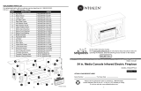
Parts and Hardware List
Please read completely through the instructions and verify that all listed parts and hardware are present
before beginning assembly.
A- Top Panel (Qty. 1) B- Fixed Shelf (Qty. 2) C- Bottom Panel (Qty. 1)
D- Top Stretcher (Qty. 2) E- Base Front Stretcher (Qty. 1) F- Base Back Stretcher (Qty. 1)
G- Base Side Stretcher (Qty. 2) H- Adjustable Shelf (Qty. 3) I- Left Side Panel (Qty. 1)
J- Right Side Panel (Qty. 1) K- Left Door (Qty. 1)
L- Right Door (Qty. 1) M- Back Panel (Qty. 1)
(1) Cam Lock (2) Cam Bolt (3) M8 x 30 mm Wood Dowel
(Qty. 26+1 extra) (Qty. 26+1 extra) (Qty. 32+1 extra)
(4) M4 x 32 mm Screw (5) M4 x 50 mm Screw (6) M3.5 x 15 mm Washer Head Screw
(Qty. 10+1 extra) (Qty. 4+1 extra) (Qty. 32+1 extra)
(7) Handle (8) 32mm Handle Bolt (9) Shelf Support (10) Rubber Bumper
(Qty. 2) (Qty. 4) (Qty. 12+1 extra) (Qty. 4+1 extra)
Glue Touch-up Pen Tipping Restraint Hardware Kit (Qty. 2)
(Qty. 1) (Qty. 1) (Included in plastic bag)
Tools required: Phillips screwdriver and rubber mallet (not provided).

5
Assembly Instructions
1. Unpack the unit and confirm that you have all the hardware and required parts. Assemble the unit on a
carpeted floor or the empty carton to avoid any scratch.
2. Securely screw the Cam Bolts (2) into the designated small holes on the Panels (A, C, I and J) and the
Bottom Stretchers (E and F) using a Phillips screwdriver.
Cam Bolt
(26 used in this step)
②

6
Assembly Instructions
3. Glue four Wood Dowels (3) into the inner holes of the Top Stretchers (D) and attach them to the Top
Panel (A) with ten 32 mm Wood Screws (4).
D
D
3
3
3
3
4
4
4
4
4
4
4
M8 x 30 mm Wood Dowel
(4 used in this step)
③
M4 x 32 mm Screw
(10 used in this step)
④

7
Assembly Instructions
4. Attach two Fixed Shelves (B) between the Side Panels (I and J) with eight Wood Dowels (3) and eight
Cam Locks (1) (Refer to page 3 on Cam Lock system operation supplement).
B
B
I
3
1
UP
UP
Cam Lock
(8 used in this step)
①
M8 x 30 mm Wood Dowel
(8 used in this step)
③

8
Assembly Instructions
5. Attach the Top Panel assembly to the top of Side Panels (I and J) with four Wood Dowels (3) and four
Cam Locks (1).
M8 x 30 mm Wood Dowel
(4 used in this step)
③
Cam Lock
(4 used in this step)
①
3
1
B
B
A
I
J

9
Assembly Instructions
6. Combine the Base Front Stretcher (E), Back Stretcher (F) and Side Stretchers (G) together with four
Wood Dowels (3) and four Cam Locks (1).
F
E
G
G
3
3
3
3
1
1
1
1
M8 x 30 mm Wood Dowel
(4 used in this step)
③
Cam Lock
(4 used in this step)
①

10
Assembly Instructions
7. Attach the assembled base to the Bottom Panel (C) with the Wood Dowels (3) and the Cam Locks (1).
M8 x 30 mm Wood Dowel
(8 used in this step)
③
Cam Lock
(10 used in this step)
①
1
3
F
E
G
G
C

11
Assembly Instructions
8. Attach the assembled base to the Side Panels (I and J) with four Wood Dowels (3) and four 50 mm
Screws (5).
M8 x 30 mm Wood Dowel
(4 used in this step)
③
M4 x 50 mm Screw
(4 used in this step)
⑤
C
E
I
J
3
3
5
5

12
Assembly Instructions
9. Now, go back and tighten all Cam Locks and Screws. Make sure that all the parts are tight and there are
no gaps between the parts. This will help keep the unit square.
10. Unfold the Back Panel (M) and position it onto the back edges of the assembly. Make sure that the
overlaps on the panels are even all the way around. Secure the Back Panel (M) in place with the 15 mm
Washer Head Screws (6).
NOTE: We recommend attaching back panel with the screws at the corners first.
M3.5 x 15 mm Washer Head Screw
(32 used in this step)
⑥
UP
M
M
J
C
6

13
Assembly Instructions
11. Stand the unit upright.
12. Insert the Shelf Supports (9) into the desired holes on the side panels (I and J). Make sure you place the
four Shelf Supports in the same level so the shelf is not tilted. Tilt and rest the Adjustable Shelves (H)
onto the Shelf Supports (9).
Shelf Support
(8 used in this step)
⑨
H
H
H
9
9
H
I
/J
J
I

14
Assembly Instructions
13. Attach the Handle (7) to the front of each Door (K and L) with two 32mm Handle Bolts (8).
Handle
(2 used in this step)
⑦
32mm Handle Bolt
(4 used in this step)
⑧
7
7
8
8
K
L

15
Assembly Instructions
14. Pick up the Right Door (L) and attach the extended Hinge Arms to the Hinge Bases installed on Right Side
Panel (J). Loosen the bolt on the back of Hinge Base for a comfortable fit. Align and insert the “U” slot on
Hinge Arm under the bolt head on the back of Hinge Base. Make sure that both door hinges engage and
function properly. Tighten the bolt on the Hinge Base to lock the hinges in place.
15. Repeat the same procedure to attach the Left Door (K) to the Left Side Panel (I).
16. Open and close the doors to make sure they are aligned and shut correctly. If necessary, adjust the screws
for a good fit. Refer to the hinge sticker on door for adjustment.
17. Stick the Rubber Bumpers (10) on the outer corners of Doors (K and L) where they meet the Top Front
Stretcher (D) and the Bottom Panel (C).
Rubber Bumper
(4 used in this step)
⑩
1
L
K
10
10
I
/J
K/L
K/L
I
/J
K/L
J
I

16
Assembly Instructions
Tools required (not provided): Phillips screwdriver, stud finder, power drill and 3 mm/0.1 in drill bit.
18. Ask for assistance to position the unit at the desired location against a wall. If necessary, adjust the pre-
attached floor levelers at the bottom of the Base Front Stretcher (E) to level the unit.
19. Follow the instructions printed on the plastic bag containing the Tipping Restraint Hardware to attach
the tip-over restraints to the unit and the wall.
NOTE: The tipping restraint hardware included is for wooden stud wall construction. It must be
attached to a wall stud. Depending upon your wall construction, different anchor hardware maybe
required. Please contact your local hardware store for assistance. Young children can be seriously
injured by tipping furniture. You must install the Tipping Restraint Hardware with the unit to
prevent the unit from tipping, causing any accidents or damage. The tipping restraints are intended
only as a deterrent, they are not a substitute for proper adult supervision. The tipping restraints are
not earthquake restraints. If you wish to add the extra security of earthquake restraints, they must be
purchased and installed separately.
20. The unit is now ready for use.

17
Care and Maintenance
Use a soft, clean cloth that will not scratch the surface when dusting.
Use of furniture polish is not necessary. Should you choose to use polish, test first in an inconspicuous area.
Using solvents of any kind on your furniture may damage the finish.
Never use water to clean your furniture as it may cause damage to the finish.
Always use coasters under beverage glasses and flowerpots.
Liquid spills should be removed immediately. Using a soft, clean cloth, blot the spill gently. Avoid rubbing.
Always use protective pads under hot dishes and plates. Heat can cause chemical changes that may create
spotting within the furniture finish.
In the event that your furniture is stained or otherwise damaged during use, we recommend that you call a
professional to repair your furniture.
Check bolts/screws periodically and tighten them if necessary.
Further Advice about Furniture Care
It is best to keep your furniture in a climate-controlled environment. Extreme temperature and humidity
changes can cause fading, warping, shrinking and splitting of wood. It is advised to keep furniture away from
direct sunlight as sun may damage the finish.
Proper care and cleaning at home will extend the life of your purchase. Follow these important and helpful tips
that will enhance your furniture as it ages.
A touch-up pen has been provided to minimize the small nicks or scratches that may occur during
assembly or shipping.
We hope you enjoy your purchase for many years.
Thank you for your purchase!
QUALITY GUARANTEE
We are confident that you will be delighted with your Whalen Furniture purchase.
Should this product be defective in workmanship or materials or fail under normal use, we will repair
or replace it for up to one (1) year from date of purchase. Every Whalen Furniture product is
designed to meet your highest expectations. We guarantee that you will immediately see the value of
our fine furniture.
This warranty gives you specific legal rights and you may also have other rights which vary from
State to State.
Customer Service: 866-942-5362
8:30 a.m. - 4:30 p.m., PST, Monday to Friday
www.whalenstyle.com


ESTE INSTRUCTIVO CONTIENE INFORMACIÓN IMPORTANTE DE SEGURIDAD.
POR FAVOR LEA Y MANTENGA PARA USO FUTURO.
Fecha: 2018-07-10 Rev. 0001-B Fábrica: KONRIC
Gabinete Ellis tipo librero con persianas
Serie # BH48-084-099-12
ENSAMBLE REQUERIDO POR ADULTOS
Si tiene alguna pregunta relacionada con el montaje o si faltan piezas, NO devuelva este producto al
establecimiento donde lo adquirió. Por favor llame a nuestro número de servicio al cliente y tienen
sus instrucciones y lista de piezas listo para proporcionar el nombre del modelo, el nombre o el
número de parte de la fábrica:
866-942-5362
Hora estándar del Pacífico: 8:30 am - 4:30 pm, de Lunes - Viernes
O visite nuestro sitio web las 24 horas del día, 7 días a la semana para recibir asistencia del producto
en www.whalenstyle.com
O por correo electrónico su petición a parts@whalenfurniture.com
NÚMERO DEL LOTE:
FECHA DE COMPRA / /

2
FABRICANTE: Whalen Furniture Manufacturing
CATALOGO: Gabinete Ellis tipo librero con persianas
MODELO # BH48-084-099-12
HECHO EN CHINA
Como ajustar las bisagras Europeas ajustables en las puertas
El envio puede causar que las puertas se desalineen. Si encuentra que las puertas necesitan una
ajustada, gire el tornillo apropiado, como esta ilustrado.
1. PARA AJUSTAR LA PUERTA HACIA ADELANTE O
HACIA ATRAS.
2. PARA AJUSTAR LA PUERTA HACIA LA DERECHA O
HACIA LA IZQUIERDA.
3. PARA AJUSTAR LA PUERTA HACIA ARRIBA O
HACIA ABAJO.
CARGA MÁXIMA 50 lb. (22.7 kg)
1
2
M Á X IM O P E S O RE C O M EN D AD O
ESTA UNIDAD DEBE UTILIZARSE CON LOS PESOS MÁXIMOS
INDICADOS. SI SE EXCEDE EL PESO MÁXIMO, PODRIA RESULTAR EN UNA
INESTABILIDAD DE LA UNIDAD CAUSANDO POSIBLES LESIONES.
/