Page is loading ...

Serial Number Purchase Date
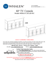
Please call for replacement parts or assistance: 1-866-942-5362
Pacic Standard Time: 8:30 a.m. – 4:30 p.m., PST, Monday to Friday
Or visit our web site: www.whalenfurniture.com
ATTACH YOUR RECEIPT HERE
ITEM # 1031287
MODEL # WSLWFP54-6
Español p. 15
54 in. Media Console Infrared Electric Fireplace
1
REPLACEMENT PARTS LIST
For replacement parts, call our customer service department at 1-866-942-5362,
8:30 a.m. - 4:30 p.m., PST, Monday - Friday.
Printed in China
PART DESCRIPTION PART#
A Top Panel *WSLWFP54-6-01-TP
B Bottom Panel *WSLWFP54-6-02-BP
C Center Shelf *WSLWFP54-6-03-CS
D Left Side Frame *WSLWFP54-6-04-LSF
E Right Side Frame *WSLWFP54-6-05-RSF
F Left Partition Panel *WSLWFP54-6-06-LPP
G Right Partition Panel *WSLWFP54-6-07-RPP
H Upper Partition Panel *WSLWFP54-6-08-UPP
I Bottom Back Stretcher *WSLWFP54-6-09-BBS
J Bottom Front Stretcher *WSLWFP54-6-10-BFS
K Bottom Front Molding *WSLWFP54-6-11-BFM
L Middle Crossbar *WSLWFP54-6-12-MC
M Adjustable Shelf *WSLWFP54-6-13-AS
N Left Door *WSLWFP54-6-14-LD
O Right Door *WSLWFP54-6-15-RD
P Door Glass *WSLWFP54-6-16-DG
Q Upper Back Panel *WSLWFP54-6-17-UBP
R Lower Back Panel *WSLWFP54-6-18-LBP
S Wood Door Panel *WSLWFP54-6-19-WDP
Door Hinge with Screws *WSLWFP54-6-20-DHS
Complete Hardware *WSLWFP54-6-CH
Complete Fireplace Inert *SF127-26AI2D-CFI
Remote Control 6-Buttom *SF127-26AI2D-RC6B
14
On-line Video Instruction Guides
Go to www.guides.sellpoints.com to view step-by-step instructional videos for
operating the replace. Enter the following product number on the website.
WSLWFP54-6
A
P
N
O
G
I
S
R
R
Q
H
J
K
M
M
B
C
D
E
F
L

32
TABLE OF CONTENTS
Wood Dowel Installation...................................................................................................... 2
Package Contents............................................................................................................... 3
Hardware Contents..............................................................................................................4
Safety Information............................................................................................................... 5
Preparation ......................................................................................................................... 5
Assembly Instructions.......................................................................................................... 6
Care and Maintenance ......................................................................................................13
One-Year Warranty ........................................................................................................... 13
Replacement Parts List ..................................................................................................... 14
WOOD DOWEL INSTALLATION
1. Apply glue to each dowel prior to inserting the dowel into the hole. Excess glue can be wiped o
with damp cloth.
2. Insert dowel at least half way by tapping lightly with a rubber mallet if necessary.
NOTE: IT IS VERY IMPORTANT TO USE GLUE WITH DOWELS.
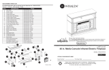
PACKAGE CONTENTS
PART DESCRIPTION QUANTITY
A Top Panel 1
B Bottom Panel 1
C Center Shelf 1
D Left Side Frame 1
E Right Side Frame 1
F Left Partition Panel 1
G Right Partition Panel 1
H Upper Partition Panel 1
I Bottom Back Stretcher 1
J Bottom Front Stretcher 1
PART DESCRIPTION QUANTITY
K Bottom Front Molding 1
L Middle Crossbar 1
M Adjustable Shelf 2
N Left Door 1
O Right Door 1
P Door Glass 2
Q Upper Back Panel 1
R Lower Back Panel 2
S Wood Door Panel (pre-attached) 2
Fireplace Insert 1
Remote Control with Battery 1
CAM LOCK SYSTEM OPERATION
1. Screw the Cam Bolt into the threaded inserts on the panel. Connect both panels together; making
sure Cam Bolt goes into the pre-drilled hole on the end of panel for Cam Lock.
2. Insert the Cam Lock into the pre-drilled large hole on the panel. Make sure the arrow on the face
of Cam Lock faces out and points towards Cam Bolt.
3. Take a Phillips screwdriver and rotate the Cam Lock clockwise to lock the Cam Bolt in place.
4. Plug the Cam Lock Cover into the cross slot of the Cam Lock to conceal the Cam.
A
P
N
O
I
S
R
R
Q
H
L
J
K
M
M
B
C
D
E
F
G

HARDWARE CONTENTS (shown actual size)
Cam Lock
Qty. 31+1 extra
Metal Bracket
Qty. 2
Com Bolt
Qty. 31+1 extra
Touch-up Pen
Qty. 1
Shelf Pin
Qty. 8+1 extra
Glue
Qty. 1
Tipping Restraint
Hardware Kit
Qty. 2
1/4” x 2” Bolt
Qty. 2
Acrylic Stopper
Qty. 1
AA
FF
BB
GG
CC
HH
WW
DD EE
SAFETY INFORMATION
Please read and understand this entire manual before attempting to assemble, operate or install
the product.
• Do not allow children to climb or play in or around this product.
• Use this unit for its intended purpose only. Do not use shelves as step ladder.
• To avoid damage, assemble the product on a sturdy, level and protective surface.
• Two people should work together to assemble the unit.
• Make sure all bolts/screws are tightly fastened before the unit is used.
• Check bolts/screws periodically and tighten them if necessary.
• Do not push furniture, especially on carpeted oor. Have someone help you lift the item and
place it in its new location. Remove any shelves before moving.
WARNING
T
his unit is not intended for use with CRT TVs. Use only with at panel TVs and audio/video equipment
meeting recommended size and weight limits. Never use with larger/heavier than recommended
at
panel TVs or equipment. To avoid instability, place at panel TV in the center of the unit; the
base
of the television must be able to rest on the supporting surface of the unit without over-hanging
the
edges. Improperly positioned at panel TVs, or at panel TVs or other equipment that exceed rec
-
ommended size and weight limits could fall o or break the unit, causing possible serious injury.
PREPARATION
Before beginning assembly of product, make sure all parts are present. Compare parts with package
contents list and hardware contents list. If any part is missing or damaged, do not attempt to
assemble the product.
Estimated Assembly Time: 60 minutes
Tools Required for Assembly (not included): Phillips screwdriver, power drill, 3/8 in. drill bit,
marking pencil and hammer.
5
4
Place TV behind the stopper
Fits up to most 165.1 cm / 65 in. at panel TVs
Maximum load 61.3 kg / 135 lb
Maximum load 22.7 kg / 50 lb
M8 x 30 mm
Wood Dowel
Qty. 34+1 extra
M3.5 x 15 mm
Screw
Qty. 12+1 extra
M3.5 x 15 mm
Washer Head Screw
Qty. 34+1 extra
M4 x 50 mm
Screw
Qty. 6+1 extra
KK
LL
MM
UUTTSS VV
Cam Lock Cover
Qty. 18+1 extra
II
JJ
L-shaped Metal Brace
Qty. 2
Handle Bolt
Qty. 4
Handle
Qty. 2
Hex Wrench
Qty. 1
Lock Washer
Qty. 2
Flat Washer
Qty. 2
Corner Connector
Qty. 2
Floor Leveler
Qty. 2
Rubber Bumper
Qty. 4+1 extra
NN OO PP QQ RR

1
1a. Unpack the unit and conrm that you have all the hardware and
required parts. Assemble the unit on a carpeted oor or the empty
carton to avoid any scratch.
1b. Securely screw 31 cam bolts (BB) into the designated small holes
on the top panel (A), bottom panel (B) and center shelf (C). Fully
tighten with a Phillips screwdriver.
ASSEMBLY INSTRUCTIONS
Hardware Used
Cam Bolt x 31
BB
4
4. Glue four wood dowels (CC) into the bottom inner holes of
both lower partition panels (F and G) and attach them to the
bottom panel (B) with four long screws (FF).
Hardware Used
3
3. Glue four wood dowels (CC) into the top inner holes of both
partition panels (F and G) and attach them to the center shelf
(C) with four cam locks (AA).
Hardware Used
Wood Dowel x 2
Wood Dowel x 4
Cam Lock x 3
Cam Lock x 4
Glue x 1
Glue x 1
2
2. Glue two wood dowels (CC) into the inner holes of middle
crossbar (L) and attach it to the center shelf (C) by engaging
three cam locks (AA).
A
B
C
D
C
C
L
E
B
E
D
Hardware Used
AA
AA
CC
CC
UU
UU
ASSEMBLY INSTRUCTIONS
6
6a. Glue ten wood dowels (CC) into the inner holes of the previous
assembly at both ends.
6b. Align the large holes on both side frames (D and E) with the
inserted wood dowels and press them together. Attach the side
frames (D and E) in place by engaging ten cam locks (AA).
5
Hardware Used
Hardware Used
76
BB
G
F
I
I
AA
AA
AA
FF
CC
CC
CC
CC
Wood Dowel x 4
Long Screw x 4
Glue x 1
FF
CC
UU
J
Wood Dowel x 6
Wood Dowel x 10
Cam Lock x 8
Raw edge
The stiles
face inward
The cam locks
face inward
Cam Lock x 10
Glue x 1
Glue x 1
AA
AA
CC
CC
UU
UU
CC
AA
G
F
B
B
C
5. Glue six wood dowels(CC) into the inner holes of the bottom
stretchers (I and J) and attach them to the bottom panel (B)
by engaging eight cam locks (AA).

Wood Dowel x 5
Cam Lock x 6
Glue x 1
Glue x 1
AA
AA
CC
CC
UU
UU
Wood Dowel x 2
Wood Dowel x 1
CC
CC
7
7. With the pilot holes as a guide, fasten two corner connectors (PP)
to the joints where the front stretcher (J) meets the side frames
(D and E), using four short screws (DD) per connector.
ASSEMBLY INSTRUCTIONS
Hardware Used
10
10. Align and attach the upper partition panel (H) to the center shelf
(C) with one wood dowel (CC) and two long screws (FF).
Hardware Used
9
9. Align and attach the bottom front molding (K) to the bottom front
stretcher (J) with two wood dowels (CC), two bolts (MM), two
lock washers (NN) and two at washers (OO).
Hardware Used
8
8. Screw two oor levelers (QQ) onto the installed corner
connectors (PP).
Hardware Used
ASSEMBLY INSTRUCTIONS
12
12. Ask for assistance to ip the assembled unit around at its front
edges. Attach two metal brackets (GG) at the joints where the
middle crossbar (L) meets the lower partition panels (F and G)
with four short screws (DD).
11
11a. Glue ve wood dowels (CC) to the top inner holes of both side
frames (D and E) and the upper partition panel (H).
11b. Ask for assistance to position the top panel (A) onto the inserted
wood dowels (CC) and attach it into place by engaging six cam
locks (AA).
The molding faces front of the unit
Hardware Used
Hardware Used
98
Corner Connector x 2
M3.5 x 15 mm Screw x 8
DD
PP
Flat Washer x 2
Lock Washer x 2
Floor Leveler x 2
2” Bolt x 2
MM
NN
OO
D
D
D
E
J
DD
PP
PP
CC
DD
GG
NN
OO
CC
MM
QQ
QQ
H
C
A
H
F
FF
J
K
M4 x 50 mm Screw x 2
M3.5 x 15 mm Screw x 4
Metal Bracket x 2
QQ
FF
G
L
GG
DD

18
L
B
R
R
ASSEMBLY INSTRUCTIONS ASSEMBLY INSTRUCTIONS
15
15. Attach one handle (JJ) to the front side of each door (N and O)
with the provided handle bolts (KK).
E
E
D
D
D
N
O
N
N
O
O
N
G
O
Q
R
F
R
C
17
17a. Pick up left door (N) and attach the extended hinge arms to the
hinge bases installed on the left side frame (D). Loosen the bolt on
the back of the hinge base for an easy t. Align and insert the “U”
slot on the hinge arm under the bolt head on the back of the hinge
base.
Make sure that both door hinges engage and function properly.
Tighten the bolt on the hinge base to lock the hinges in place.
17b.
Repeat the same procedure to attach the right door (O) at the
opposite
side.
17c. Open and close the doors to make sure they are aligned and shut
correctly. If necessary, adjust the screws for a good t. Refer to the
hinge sticker on the door for adjustment.
17d. Stick the rubber bumpers (RR) at the outer corners of both doors
(N and O) where they meet with the partition panels (F and G).
Hardware Used
Hardware Used
Hardware Used
Hardware Used
Rubber Bumper
Washer Head Screw x 32
Cam Lock Cover x 18
Shelf Pin x 8
Handle x 2
x 2
Handle Bolt x 4
x 4
1110
16
Follow these steps if you want to change your replace door
panels from wood (S) to glass (P). Otherwise, skip to Step 17.
16A. Take the left door (N) and loosen the screws on the inside of
the door frame.
16B. Rotate the clips to remove the old panel.
16C. Insert the new panel, then rotate the clips and tighten the
screws to secure the panel in the door frame.
16D. Repeat this process with right door (O).
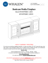
18. Lift the replace insert carefully into the back of the assembled
mantel and center it in the opening. DO NOT drag the insert
across the bottom panel (B) as it may scratch the unit.
Electric
Firebox
Installing the replace insert
14
14a. Carefully stand the unit upright.
14b. Insert four shelf pins (II) into the desired holes inside
each side compartment. Make sure you place the 4 shelf
pins in the same level so the shelf is not tilted. Tilt and
rest the adjustable shelves (M) onto the shelf pins (II).
14c. Plug the cam lock covers (HH) onto the visible cams
locks (AA) to conceal the cams.
13a. Pick up the upper back panel (Q) and align the drilled holes
with the pilot holes on the back of the top panel (A). Attach
the upper back panel (Q) in place with the provided washer
head screws (EE).
13b. Align and attach two lower back panels (R) to the side
frames (D and E) and lower partition panels (F and G) with
the provided washer head screws (EE), using the plots holes
as a guide.
UP
UP
M
G
13
1
EE
EE
HH
II
II
II
M
KK
KK
JJ
JJ
P
S
RR
RR
HH

20a. Remove the paper backing from acrylic stopper (SS), then
properly align the acrylic stopper into the cut-out on the acrylic
stopper template on the front of the top panel (A). Press down
on the acrylic stopper to help adhesion.
20b. At the back of top panel (A), grip the head of plastic tack with
pliers, with twisting motion pull tack loose to remove the acrylic
stopper template.
NOTE: You must install the acrylic TV stopper to prevent
TV from tipping when placing your at panel television on
the top panel.
B
A
Hardware Used
Acrylic Stopper
x 1
SS
SS
19. Using the pilot holes as a guide, align and attach L-shaped metal
braces (LL) to the bottom panel (B) by screwing one washer
head screw (EE) in each.
Hardware Used
Washer Head Screw
L-shaped Metal Brace
x 2
x 2
EE
EE
LL
LL
The rubber bumper is
against the rebox
19
21
20
Connector
Wooden stud
Short
Screw
Metal Bracket
Long Screw
Floor
Leveler
Wall
Wall
CARE AND MAINTENANCE
CARING FOR WOOD FURNITURE
CLEANING THE FIREPLACE TRIM
A touch-up pen has been provided to minimize the small nicks or scratches that may occur during assembly or shipping.
To clean and care for your furniture:
• Use a soft, clean cloth that will not scratch the surface when dusting.
• Use of furniture polishes is not necessary. Should you choose to use polishes, test rst in an inconspicuous area.
• Using solvents of any kind on your furniture may damage the nish.
• Never use water to clean your furniture as it may cause damage to the nish.
• Always use coasters under beverage glasses and owerpots.
• Liquid spills should be removed immediately. Using a soft clean cloth, blot the spill gently. Avoid rubbing.
• Always use protective pads under hot dishes and plates. Heat can cause chemical changes that may create spotting
within the furniture nish.
• Stains or marks from crayons or ink markers will be dicult to remove.
• In the event that your furniture is stained or otherwise damaged during use, we recommend that you call a professional
to repair your furniture.
• Check bolts/screws periodically and tighten them if necessary.
• It is best to keep your furniture in a climate-controlled environment. Extreme temperature and humidity changes can cause
fading, warping, shrinking and splitting of wood. It is advised to keep furniture away from direct sunlight as sun may damage
the nish.
• Proper care and cleaning at home will extend the life of your purchase. Following these important and helpful tips will enhance
your furniture as it ages.
Clean the metal trim using a soft cloth, slightly dampened with citrus oil based product and bu with a clean soft cloth. DO NOT
use brass polish or household cleaners as these products will damage the metal trim. Citrus oil based products can be obtained
at supermarkets or hardware stores.
This product is warranted to the original purchaser. If there is a failure in this unit due to defects in materials or workmanship,
the manufacturer will repair or replace this item at our discretion without charge. Warranty is void if product has been assembled
incorrectly, misused, abused by overloading, altered in any way or damaged due to accident. This warranty is not transferable
and does not cover chipping, aking, scratches, rust, dents, or other damages to the surfaces of this product. Responsibility
of the manufacturer is limited to repair or replacement of this product. The manufacturer is not responsible for consequential,
incidental, or other damages or losses resulting from product failure.
This warranty is in lieu of all other expressed warranties. Some states do not allow the exclusion or limitation of incidental or
consequential damages, so the above limitation may not apply to you. This warranty gives you specic legal rights and you may
have other rights which vary from state to state.
ONE-YEAR LIMITED WARRANTY
13
ASSEMBLY INSTRUCTIONS
NOTE: Young children can be seriously injured by tipping furniture. You
must install the tipping restraint hardware with the unit to prevent the unit
from tipping, causing any accidents or damage. The tipping restraints are
intended only as a deterrent, they are not a substitute for proper adult
supervision. The tipping restraints are not earthquake restraints. If you
wish to add the extra security of earthquake restraints, they must be
purchased and installed separately.
19a. With assistance, position the assembled replace console at the desired
location against a wall. In case of uneven oor, oor levelers are provided
at the bottom of the mantel. If necessary, adjust the oor levelers by hand
to correct tilting and/or level the doors, until the unit is level.
19b. Follow the instructions printed on the plastic bag containing the tipping
hardware to attach the tip-over restraint to the unit and the wall.
19c. Connect the replace to the power transformer. Follow the operating
manual for the electric replace insert to control your replace.
Hardware Used
Tipping Restraint
Hardware Kit
x 2
WW
Installing the tipping restraint hardware
12

Número de serie
Fecha de compra
Por favor llame para repuestos o asistencia: 1-866-942-5362
Hora estándar del pacíco: 8:30 a.m. - 4:30 p.m., PST, de lunes a viernes
O visite nuestra página de internet www.whalenfurniture.com
ADJUNTAR SU RECIBO AQUÍ
ARTÍCULO # 1031287
MODELO # WSLWFP54-6
Español p. 15
Consola con chimenea eléctrica infrarroja de 54”
15
REEMPLAZO DE LAS PIEZAS
Para piezas de repuesto, llame a nuestro departamento de servicio al cliente al 1-866-942-5362,
de 8:30 a.m. - 4:30 p.m., PST, Lunes – Viernes.
Impreso en China
PARTE DESCRIPCIÓN PARTE#
A Panel superior *WSLWFP54-6-01-TP
B Panel inferior *WSLWFP54-6-02-BP
C Repisa central
*WSLWFP54-6-03-CS
D Marco izquierda lateral *WSLWFP54-6-04-LSF
E Marco derecho lateral *WSLWFP54-6-05-RSF
F Panel divisor izquierdo *WSLWFP54-6-06-LPP
G Panel divisor derecho *WSLWFP54-6-07-RPP
H Panel divisorio superior *WSLWFP54-6-08-UPP
I Soporte posterior inferior *WSLWFP54-6-09-BBS
J Soporte frontal inferior *WSLWFP54-6-10-BFS
K Moldura inferior frontal *WSLWFP54-6-11-BFM
L Soporte central *WSLWFP54-6-12-MC
M Repisa ajustable *WSLWFP54-6-13-AS
N Puerta izquierda *WSLWFP54-6-14-LD
O Puerta derecha *WSLWFP54-6-15-RD
P
Panel puerta de vidrio *WSLWFP54-6-16-DG
Q Panel posterior superior *WSLWFP54-6-17-UBP
R Panel posterior inferior *WSLWFP54-6-18-LBP
S Panel puerta de madera *WSLWFP54-6-19-WDP
Bisagra de puerta con tornillos
*WSLWFP54-6-20-DHS
Herraje completo *WSLWFP54-6-CH
Inserto de chimenea completo *SF127-26AI2D-CFI
Control remoto 6-botones *SF127-26AI2D-RC6B
28
Instrucciones en video en linea
Visite www.guides.sellpoints.com para una explicación paso a paso sobre cómo
manejar la chimenea. Introduzca el siguiente número del producto en la página web.
WSLWFP54-6
A
P
N
O
G
I
S
R
R
Q
H
J
K
M
M
B
C
D
E
F
L

1716
TABLA DE CONTENIDO
Instalación de clavija de madera...................................................................................... 16
Contenidos del empaque.................................................................................................. 17
Contenidos de atículos de ferretería................................................................................. 18
Información de seguridad..................................................................................................19
Peparación ........................................................................................................................19
Instrucciones de ensamble................................................................................................ 20
Cuidado y matenimiento.................................................................................................... 27
Garantía de un año ........................................................................................................... 27
Lista de partes de repuesto............................................................................................... 28
INSTALACIÓN DE CLAVIJA DE MADERA
1. Aplicar goma a cada clavija de madera antes de insertar en el oricio. Exceso se pueden limpiar
con un paño húmedo.
2. Insertar el perno al menos a mitad de camino golpeando ligeramente con un martillo de goma,
si es necesario.
NOTA: ES MUY IMPORTANTE UTILIZAR PEGAMENTO CON LOS PERNOS.
CONTENIDO DEL PAQUETE
PARTE DESCRIPCIÓN CANT.
A Panel superior 1
B P
anel inferior 1
C Repisa central 1
D Marco izquierda lateral 1
E Marco derecho lateral 1
F Panel divisor izquierdo 1
G Panel divisor derecho 1
H Panel divisorio superior 1
I Soporte posterior inferior 1
J Soporte frontal inferior 1
PARTE DESCRIPCIÓN CANT.
K Moldura inferior frontal 1
L Soporte central 1
M Repisa ajustable 2
N Puerta izquierda 1
O Puerta derecha 1
P Panel puerta de vidrio 2
Q Panel posterior superior 1
R Panel posterior inferior 2
S
Panel puerta de madera
(
preinstalado
)
2
Inserto de chimenea completo 1
Control remoto con batería 1
SISTEMA DE OPERACIÓN DE TUERCA DE FIJACIÓN
1. Fijar los tornillos de jación en los oricios pequeños. Conectar ambos paneles, cerciorandose
que los tornillos de jación entren bien y que estos queden en los oricios al nal del panel con
tuercas de jación.
2. Inserte las tuercas de jación en los oricios grandes del panel. Hacer que la echa en la tuerca
este apuntando hacia la entrada del tornillo de jación.
3. Una vez que el tornillo esté conectado dentro, tome un destornillador de estrella y apriete la
tuerca en dirección de las manecillas del reloj.
4. Coloque la tapa de la tuerca de jación sobre la misma en la ranura de estrella, ver detalle.
Está listo para el ensamble KD de esta unidad
A
P
N
O
I
S
R
R
Q
H
L
J
K
M
M
B
C
D
E
F
G
GOMA

CONTENIDO DE HERRAJE (mostrado tamaño real)
Tuerca de jación
Cant. 31+1 extra
Soporte de metal
Cant. 2
Tornillo de jación
Cant. 31+1 extra
Plumón de retoque
Cant. 1
Soporte repisa
Cant. 8+1 extra
Goma
Cant. 1
Juego de restricción
de movimiento
Cant. 2
Perno 1/4” x 2”
Cant. 2
Tope acrílico
Cant. 1
AA
FF
BB
GG
CC
HH
WW
DD EE
INFORMACIÓN DE SEGURIDAD
Por favor lea y comprenda el manual entero antes de intentar ensamblar o instalar el producto.
• No permita que los niños se suban o jueguen en o alrededor de este producto.
• Utilice esta unidad para la que ha sido concebido. No utilice las repisas como escalera de mano.
• Para evitar daños, monte el producto en una supercie rme, nivelada y protectora.
• Dos personas deben trabajar juntos para instalar la unidad en la pared.
• Asegúrese de que todos los pernos y tornillos estén bien apretados antes de que la unidad sea utilizada.
• Revise los pernos/tornillos periódicamente y apriete en caso de ser necesario.
• No empuje muebles, sobre todo en el piso alfombrado. Pida a alguien que lo ayude a levantar el el-
emento y colocarlo en su nueva ubicación. Retire estantes antes de moverse.
ADVERTENCIA
Esta unidad no debe utilizarse con televisiones CRT o de tubo. Utilizarse únicamente con televisiones
de
pantalla plana y equipo de audio/video que tengan la medida/peso recomendado. Nunca utilizar
con televisiones más grandes/pesadas de las recomendadas. Para evitar inestabilidad coloque en
el centro de la unidad; La base de la televisión debe de reposar sobre la supercie de soporte
de la unidad sin rebasar las orillas. Televisiones de pantalla plana colocadas inapropiadamente,
o televisiones de pantalla plana incluyendo equipo que sobrepasa las medidas y pesos recomendados
pueden caerse y/o romper la unidad, causando posibles daños o lesiones.
PREPARACIÓN
Antes de empezar el ensamble del producto, asegúrese de que todas las partes estén presentes.
Compare las piezas con el contenido en la lista de partes del paquete y el diagrama de arriba. Si alguna
parte falta o está dañada, no intente ensamblar el producto. Póngase en contacto con servicio al cliente
para las piezas de re-emplazo.
Tiempo estimado de ensamblaje: 60 minutos
Herramientas Requeridas para el Ensamble (no incluidas): Destornillador estrella, taladro eléctrico,
broca de 3/8 pulgadas (9,5 mm), lápiz marcador y martillo.
19
18
POSICIONE LA TELEVISIÓN
ATRAS DEL TOPE
PARA LA MAYORÍA DE TELEVISIONES PANTALLA PLANA DE 165.1 cm / 65 pulgadas
MÁXIMA CARGA 61.3 kg / 135 libras
MÁXIMA CARGA 22.7 kg / 50 libras
Perno M8 x 30 mm
de madera
Cant. 34+1 extra
Tornillo de
M3.5 x 15 mm
Cant. 12+1 extra
Tornillo de cabeza
arandela M3.5 x 15 mm
Cant. 34+1 extra
Tornillo de
M4 x 50 mm
Cant. 6+1 extra
KK
LL
MM
UUTTSS VV
Cubierta de tuerca
Cant. 18+1 extra
II
JJ
Abrazadera metal en
forma de L
Cant. 2
Tornillo para jaladera
Cant. 4
Jaladera
Cant. 2
Llave hexagonal
Cant. 1
Arandela de presión
Cant. 2
Arandela plana
Cant. 2
Conector esquina
Cant. 2
Nivelador de piso
Cant. 2
Tope plástico
Cant. 4+1 extra
NN OO PP QQ RR

1
1a. Desempacar la unidad y conrmar que se tiene todo el herraje y
partes requeridas. Ensamble la unidad sobre un área con alfombra o
sobre el cartón para evitar daños a las piezas.
1b. Atornille 31 tornillos de jación (BB) en los oricios pequeños desig-
nados en el panel superior (A), el panel inferior (B) y el repisa central
(C) como se muestra. Ajústelos correctamente con un destornillador
estrella.
INSTRUCCIONES DE ENSAMBLE
Herraje Utilizado
T
ornillo de jación x 31
BB
4
4. Pegar cuatro clavijas de madera (CC) en los oricios interiores
inferiores des los paneles divisorios inferiores (F y G) y adjuntarlo
al panel inferior (B) con cuatro tornillos largos (FF).
Herraje Utilizado
3
3. Pegar cuatro clavijas de madera (CC) en los oricios interiores
superiores de los paneles divisorios inferiores (F y G) y adjuntarlo
a la repisa central (C) con cuatro tuercas de jación (AA).
Herraje Utilizado
Clavija de madera x 2
Clavija de madera x 4
Tuerca de jación x 3
Tuerca de jación x 4
Goma x 1
Goma x 1
2
2. Pegar 2 clavijas de madera (CC) en los oricios interiores del
soporte central (L) y adjuntarlo al repisa central (C) mediante la
participación de tres tuercas de jación (AA) como se muestra.
A
B
C
D
C
C
L
E
B
E
D
Herraje Utilizado
AA
AA
CC
CC
UU
UU
INSTRUCCIONES DE ENSAMBLE
6
6a. Pegue diez clavijas de madera (CC) al interior de los oricios
del montaje previo en ambos bordes.
6b. Alinear los oricios grandes en ambos marcos laterales (D
y E) con las clavijas de madera ya insertadas y presiónelas
hasta encajar. Adjuntar los marcos laterales (D y E) usando
diez tuercas de jación (AA).
5
Herraje Utilizado
Herraje Utilizado
2120
BB
G
F
I
I
AA
AA
AA
FF
CC
CC
CC
CC
Clavija de madera x 4
Tornillo M4x50 mm x 4
Goma x 1
FF
CC
UU
J
Clavija de madera x 6
Clavija de madera x 10
Tuerca de jación x 8
Borde sin
acabado
Las molduras
medias apuntan
hacia adentro
Las tuercas de
jación apuntan
hacia adentro
Tuerca de jación x 10
Goma x 1
Goma x 1
AA
AA
CC
CC
UU
UU
CC
AA
G
F
B
B
C
5. Pegar seis clavijas de madera (CC) en los oricios interiores de
los soportes inferiores (I y J) y adjuntarlo al panel inferior (B)
mediante la participación de echo tuercas de jación (AA).

Clavija de madera x 5
Tuerca de jación x 6
Goma x 1
Goma x 1
AA
AA
CC
CC
UU
UU
Clavija de madera x 2
Clavija de madera x 1
CC
CC
7
7. Con los agujeros piloto como guía, ajuste dos connectores
esquina (PP) en la junta donde la soporte frontal inferior
(J) se encuentra con los marcos laterales (D y E), usando
cuatro tornillos cortos (DD) por conector.
INSTRUCCIONES DE ENSAMBLE
Herraje Utilizado
10
10. Alinear y adjuntar el panel divisorio superior (H) a la repisa
central (C) con una clavija de madera (CC) y dos tornillos
largos (FF).
Herraje Utilizado
9
9. Alinear y adjuntar la moldura inferior frontal (K) al soporte frontal
inferior (J) con dos clavijas de madera (CC), dos pernos (MM),
dos arandelas de presión (NN) and dos arnadelas planas (OO).
Herraje Utilizado
8
8. Atornille dos niveladores de piso (QQ) a los conectores
esquina ya instaladas (PP).
Herraje Utilizado
INSTRUCCIONES DE ENSAMBLE
12
12. Pida ayuda para girar la unidad ensamblada en torno a sus
bordes delanteros. Adjuntar dos soportes de metal (GG)
a las juntas donde el soporte central (L) se encuentra con
los paneles divisorios inferiores (F y G) con cuatro tornillos
cortos (DD).
11
11a. Pegue cinco clavijas de madera (CC) en los oricios interiores
superiores de los marcos laterales (D y E) y el panel divisorio
superior (H).
11b. Pida ayuda para posicionar el panel superior (A) en las clavijas
de madera y las insertadas (CC) y jarlos en su lugar mediante
la participación de seis tuercas de jación (AA).
La moldura apunta hacia el frente de la unidad
Herraje Utilizado
Herraje Utilizado
2322
Conector esquina x 2
Tornillo de M3.5 x 15 mm x 8
DD
PP
Arandela plana x 2
Arandela de presión x 2
Nivelador de piso x 2
Perno de 2” x 2
MM
NN
OO
D
D
D
E
J
DD
PP
PP
CC
DD
GG
NN
OO
CC
MM
QQ
QQ
H
C
A
H
F
FF
J
K
Tornillo de M4x50 mm x 2
Tornillo de M3.5 x 15 mm x 4
Soporte de metal x 2
QQ
FF
G
L
GG
DD

18
L
B
R
R
INSTRUCCIONES DE ENSAMBLE INSTRUCCIONES DE ENSAMBLE
15
15. Adjuntar una jaladera (JJ) al lado frontal de cada puerta (N y O)
usando los pernos de jaladera proveida (KK).
E
E
D
D
D
N
O
N
N
O
O
N
G
O
Q
R
F
R
C
17
17a. Tomar la puerta izquierda (N) y conecte el brazo de bisagra
extensible a las bases de la bisagra instaladas en el marco
izquierda lateral (D). Aoje el perno en la parte trasera le la base
de la bisagra para una colocación sencilla. Alinee e inserte la
ranura en U en el brazo de la bisagra bajo la cabeza del perno
en la parte posterior de la base de la bisagra. Asegúrese de
que ambas bisagras de las puertas se mueven y funcionan de
manera correcta. Apriete el perno en la base de la bisagra para
asegurar la bisagra en su sitio.
17b.
Repetir el mismo procedimiento para adjuntar la puerta derecha
(O) en el lado opuesto.
17c. Abrir y cerrar las puertas para asegurar de que esten alineadas y
que se cierren correctamente. Si fuera necesario, ajustar los tornillos
para un buen ajuste. Consultar la etiqueta de las bisagras en la
puerta para ajustes.
17d. Coloque los topes de goma (RR) en las esquinas de ambas
puertas (N y O) donde estas se encuentran con los paneles
divisorios (F y G).
Herraje Utilizado
Herraje Utilizado
Herraje Utilizado
Herraje Utilizado
Tope de goma
Tornillo de cabeza de arandela
x 32
Cubierta de tuerca x 18
Soporte repisa x 8
Jaladera x 2
x 2
Perno de jaladera x 4
x 4
2524
16
18. Levante la chimenea con cuidado y coloque en la parte
posterior de la unidad ensamblada y centrarla en la abertura
.
NO arrastre el inserto a través del panel inferior (B), ya que
puede rayar la unidad.
Inserto de
chimenea
Instalación del inserto de la chimenea
14
14a. Levante con cuidado la unidad.
14b. Inserte cuatro soportes de la repisa (II) en los agujeros
deseados dentro de cada lado del compartimento. Asegúrese
de que coloca los cuatro clavos de estante al mismo nivel
para que el estante no se incline. Incline y apoye las repisas
ajustables (M) en los soportes de la repisa (II).
14c.
Inserte las cubiertas de tuercas de jación (HH) en las tuercas
de jación visible (AA) para ocultarlas.
13a. Recoger el panel posterior superior (Q) y alinear los agujeros
perforados con los agujeros piloto sobre el parte posterior del
panel superior (A). Fije el panel posterior superior (Q) en su
lugar con los tornillos de cabeza arandela (EE).
13b. Alinee y adjuntar dos paneles posteriores inferiores (R) a los
marcos laterales (D y E) y a los paneles divisorios inferiores (F
y G) con los tornillos de cabeza de arandela proporcionados
(EE), usando los agujeros como guía.
ARRIBA
M
G
13
1
EE
EE
HH
II
II
II
M
KK
KK
JJ
JJ
P
S
RR
RR
HH
ARRIBA
Siga estos pasos si desea cambiar los paneles de la puerta del
mueble para televisor desde madera a vidrio. De lo contrario,
vaya al Paso 17.
16A. Tomar la puerta izquierda (N) y aoje los tornillos de la parte
interior del armazón de la puerta.
16B. Gire los ganchos para remover el panel viejo.
16C. Inserte un nuevo panel, gire los ganchos y apriete los tornillos
para asegurar el panel al armazón de la puerta.
16D. Repita este procedimiento con la puerta derecha (O).

20a. Retire el papel protector del tope acrílico (SS), alinee el tope de
acrílico en el recorte de la plantilla en la parte frontal del panel
superior (A). Presione hacia abajo en el tope acrílico (SS) para
ayudar a la adhesión.
20b. En la parte trasera del panel superior (A), agarre la cabeza de
las chinchetas con unos alicates, con un movimiento de torsión
para quitar el molde del tope.
NOTA: Es necesario instalar el tope acrílico para TV asi evitar
que el televisor se caiga al poner su televisor de pantalla
plana directamente en el panel superior.
B
A
Herraje Utilizado
Tope acrílico
x 1
SS
SS
19. Usar los agujeros piloto como una guía, alinear y colocar
abrazaderas de metal en forma de L (LL) al panel inferior (B)
jando con un tornillo de cabeza arandela (EE) en cada uno.
Herraje Utilizado
Tornillo de cabeza de arandela
Abrazadera metal en forma de L
x 2
x 2
EE
EE
LL
LL
El tope de goma queda contra
el inserto de chimenea
19
21
20
Conector
Vigas de madera
Perno
chico
Soporte de metal
Perno largo
Nivelador
de piso
Pared
Pared
CUIDADO Y MANTENIMIENTO
CUIDADO DE MUEBLES DE MADERA
LIMPIEZA DE MOLDURAS DE LA CHIMENEA
Un plumón de retoque se ha proporcionado para minimizar las muescas pequeñas o rayaduras que puedan ocurrir durante el
montaje o el envío.
• Use una toalla suave y limpia para evitar daños y rayones.
• El uso de cera para pulir muebles no es necesario. Si desea usar cera pruebe en un área que no sea visible para revisar su
funcionamiento.
• Usar solventes de cualquier tipo puede dañar el acabado del mueble.
• Nunca use agua para limpiar la unidad, ya que le puede dañar el acabado.
• Siempre utilize protección para vasos cuando los coloque sobre la unidad.
• Los derrames de líquidos se deben de limpiar inmediatamente, con una toalla suave evitando tallar.
• Siempre utilizar protectores en caso de poner cosas calientes. El calor puede provocar una reacción química en el acabado y
dañarlo.
• En caso que su unidad sea manchada durante el uso le recomendamos hablar a un profesional para que le ayude.
• Revisar los pernos y tornillos periódicamente y apriételos si es necesario.
• Mantener la madera a una temperatura adecuada. Temperaturas extremas y cambios de humedad pueden causar diferentes
daños en la madera como el encogimiento o desvanecimiento. Mantener la madera lejos de la exposición directa al sol
debido a daños en el artículo.
• El cuidado y limpieza adecuado extenderá la vida útil del producto. Si sigue estas directrices la vida útil del producto se
alargará.
Limpie las molduras de metal con un paño suave, sobre todo voy a hablar del aceite. NO use. El abrillantador se puede adquirir
en los supermercados o tiendas especializadas. Y en el sector privado.
La garantía se aplica al comprador original. En caso de defecto, el productor se encarga de los costes y la reparación o
remplazo. La garantía queda inutilizable si el montaje es erróneo, dado mal uso o sobrecarga, o dañado por algún accidente.
No es transferible y no permite el desgaste, mal uso entre otros del producto. La responsabilidad del proveedor es limitada.
El proveedor no se hace cargo de errores futuros en el artículo.
Esta garantía se basa en otras. Algunos estados no permiten benecios tras esto.
GARANTÍA DE UN AÑO
27
INSTRUCCIONES DE ENSAMBLE
NOTA: Los niños pequeños pueden sufrir lesiones graves por inclinación
de
muebles. Debe instalar el juego de restricción de movimiento con
la unidad en funcionamiento para evitar que se caiga, causando
accidentes o daños. El sistema de retención está pensado sólo como
un elemento de disuasión, no son un sustituto de la supervisión de un
adulto. El sistema de retención no es una limitación de terremoto. Si
desea agregar la seguridad adicional de las restricciones de terremotos
,
deben ser comprados e instalados por separado.
19a. Pide ayuda para colocar la unidad ensamblada en el lugar deseado
contra una pared. En el caso de suelo irregular, los niveladores de
piso se proporcionan en la parte inferior de la base. Para ajustar la
unidad en caso de inclinación o puertas que no están a nivel, basta
con inclinar de nuevo la unidad y ajuste los niveladores de piso con la
mano para corregir la inclinación y / o nivel de puertas.
19b. Siga las instrucciones impresas en la bolsa de plástico que contiene el
herraje de restricción de movimiento a la unidad y la pared.
19c. Conecte la chimenea a una fuente de potencia. Siga las instrucciones
de manejo separado de chimenea eléctrica para controlarla.
Herraje Utilizado
Juego de restricción
de movimiento
x 2
WW
Instalación de juego de restricción de movimiento
26
/