Page is loading ...

HPV 900 Series 2
Axial Flux PM
Technical Manual
NOTE: This is a supplementary manual for the PM Axial Flux. If any detail about the HPV900 Series 2
is needed, please refer to the technical manual TM7333
TM7354 Rev 20
© 2017 Magnetek Elevator

WARRANTY Standard products manufactured by the Company are warranted to be free from
defects in workmanship and material for a period of one year from the date of
shipment, and any products which are defective in workmanship or material will be
repaired or replaced, at the Company’s option, at no charge to the Buyer. Final
determination as to whether a product is actually defective rests with the Company.
The obligation of the Company hereunder shall be limited solely to repair or replace,
at the Company’s discretion, products that fall within the foregoing limitations, and
shall be conditioned upon receipt by the Company of written notice of any alleged
defects or deficiency promptly after discovery and within the warranty period, and in
the case of components or units purchased by the Company, the obligation of the
Company shall not exceed the settlement that the Company is able to obtain from the
supplier thereof. No products shall be returned to the Company without its prior
consent. Products which the company consents to have returned shall be shipped
prepaid f.o.b. the Company factory. The Company cannot assume responsibility or
accept invoices for unauthorized repairs to its components, even though defective.
The life of the products the Company depends, to a large extent, upon type of usage
thereof and THE COMPANY MAKES NO WARRANTY AS TO FITNESS OF ITS
PRODUCTS FOR THE SPECIFIC APPLICATIONS BY THE BUYER NOR AS TO
PERIOD OF SERVICE UNLESS THE COMPANY SPECIFICALLY AGREES
OTHERWISE IN WRITING AFTER PROPOSED USAGE HAS BEEN MADE KNOWN
TO IT.
This warranty does not apply to experimental products for which no warranty is made
or given and Buyer waives any claim thereto.
THE FOREGOING WARRANTY IS EXCLUSIVE AND IN LIEU OF ALL OTHER
WARRANTIES, EXPRESSED OR IMPLIED, INCLUDING, BUT LIMITED TO, ANY
WARRANTY OF MECHANTIBILITY OR OF FITNESS FOR A PARTICULAR
PURPOSE AND BUYER HEREBY WAIVES ANY AND ALL CLAIMS THEREFORE.
LIMITATIONS IN NO EVENT SHALL MAGNETEK BE LIABLE FOR LOSS OF PROFIT,
OF LIABILITY INDIRECT, CONSEQUENTIAL OR INCIDENTAL DAMAGES WHETHER
ARISING OUT OF WARRANTY, BREACH OF CONTRACT OR TORT.
HPV 900 S2 and Series 2 is a trademark of Magnetek, Inc.
All rights reserved. No part of this publication may be reproduced or used in any form or by any means - graphic, electronic, or
mechanical including photocopying, recording, taping, or information storage and retrieval systems - without written permission
of the publisher.
2017 Magnetek, Inc.

IMPORTANT
Grounding Considerations
It is very important to make proper ground connections to the drive. The drive has a
common ground bus terminal connection. All grounds need to land at this common
point including building, motor, transformer, and filter grounds. This will limit the
impedance between the grounds and noise will be channeled back to building
ground. This improves the performance of the drive.

Table of Contents
Start Up Guideline ................................................................................................................................... 1
Drive Model Number ............................................................................................................................... 2
HPV 900 Series 2 Drive Ratings ............................................................................................................... 2
HPV900 S2 Axial Flux Drive Application Kits ............................................................................................ 3
Mechanical Mounting Instructions ......................................................................................................... 6
Encoder Electrical Connection................................................................................................................. 8
Proximity Sensor Electrical Connection................................................................................................... 8
PM Drive Setup Procedure ...................................................................................................................... 9
PM Alignment Procedure ...................................................................................................................... 11
HF Inject (preferred method) ............................................................................................................ 11
Open Loop Alignment........................................................................................................................ 12
Auto Alignment Procedure ................................................................................................................ 13
Auto-Tune Procedure ............................................................................................................................ 15
Setting Auto-Tune ............................................................................................................................. 15
Troubleshooting .................................................................................................................................... 16
Timing Diagram ..................................................................................................................................... 21
Spare Parts List for HPV900 Series 2 Axial Flux ..................................................................................... 22

Start-Up Guideline
1
Start Up Guideline
1. Mechanically mount all the parts as explained in Mechanical Mounting Instructions on page 6.
Connect the encoder and proximity sensor to the drive as explained in Encoder Electrical
Connection on page 8 and Proximity Sensor Electrical Connection on page 8.
2. Then if not already pre-loaded, set all the drive parameters to parameters that are
recommended by the car controller manufacturer so the drive and controller can interface with
each other correctly; this includes all parameters in the A1 – A5 submenu and C1 – C4
submenus.
3. Proceed to PM Drive Setup Procedure on page 9 to continue with setting of motor data,
Encoder Pulses, rotor alignment, and auto-tune.
4. Refer to Troubleshooting on page 16 if there are some initial start-up problems for Axial Flux
specific problems ONLY. For general faults on the HPV900 Series 2, refer to the HPV900
Series 2 Technical Manual TM7333
NOTE: All the parts needed to get the Axial Flux drive to run are outlined on page 3 (need drive
part number HPV900-_ _ _ _-2E1-02 and kit 46S04444-_ _ _ _ )
NOTE: If the motor has a shaft, use a shaft mounted encoder. If a shaft mounted encoder is to be
used, a standard HPV900 Series 2 is recommended.

Axial Flux Drive Models
2
Drive Model Number
HPV 900 Series 2 Drive Ratings
Rated
Input
Voltage
NA
1
Rated
HP
EU
1
Rated
HP
NA
1
Rated
kW
EU
1
Rated
kW
Overload
Selection
2
Carrier
Frequency
(kHz)
3
Continuous
Output Current
General
Purpose Rating
Continuous
Output Current
Elevator Duty
Cycle Rating
Maximum
Output
Current
for 5 Sec
Frame
Size
Model Number
7.5
--
5.5
--
250%
10
25
29
63
2
HPV900-2025-2E1-02
200%
8
31
33
10
--
7.5
--
250%
10
31
36
78
2
HPV900-2031-2E1-02
200%
8
39
41
2
15
--
11
--
250%
10
41
48
103
3.5
HPV900-2041-2E1-02
3
200%
8
51
55
0
20
--
15
--
250%
10
52
60
130
3.5
HPV900-2052-2E1-02
V
200%
8
65
70
25
--
19
--
250%
10
75
87
187.5
4
HPV900-2075-2E1-02
30
--
22
--
250%
10
88
102
220
4
HPV900-2088-2E1-02
40
--
30
--
250%
10
98
114
245
5
HPV900-2098-2E1-02
5
5
3.7
3.7
250%
10
8
9
20
1
HPV900-4008-2E1-02
200%
8
10
11
7.5
5.5
5.5
4
250%
10
12
14
30
2
HPV900-4012-2E1-02
200%
8
15
16
10
7.5
7.5
5.5
250%
10
16
19
40
2
HPV900-4016-2E1-02
200%
8
20
21
15
10
11
7.5
250%
10
21
24
53
3
HPV900-4021-2E1-02
200%
8
26
28
4
20
15
15
11
250%
10
27
31
68
3
HPV900-4027-2E1-02
6
200%
8
34
36
0
25
20
19
15
250%
10
34
39
85
4
HPV900-4034-2E1-02
V
200%
8
43
45
30
25
22
18.5
250%
10
41
48
103
4
HPV900-4041-2E1-02
200%
8
51
55
40
30
30
22
250%
10
52
60
130
4
HPV900-4052-2E1-02
200%
8
65
70
50
40
37
30
250%
10
65
75
162.5
5
HPV900-4065-2E1-02
60
50
45
37
250%
10
72
84
180
5
HPV900-4072-2E1-02
75
60
56
45
250%
10
96
111
240
5
HPV900-4096-2E1-02
Table 1: HPV900 Series 2 Drive Ratings
NOTE: all ratings at 60/50Hz bases on a geared elevator application
1.
NA refers to drives sold in North America and ratings are based off of 460VAC input.
EU refers to drives sold in Europe and are based off of 400VAC input
2.
Based on Overload Select (C1) parameter selection
3.
Maximum Carrier Frequency before derating
HPV900
-
-
-
drive
input voltage
2 = 230 volt
4 = 460 volt
continuous
output current
operator style
E = Elevator
N = no operator
software program
1 = Standard Software
2 = PM Axial Flux
2
1
2
0

Axial Flux Drive Application Kits
3
HPV900 S2 Axial Flux Drive Application Kits
Application Description
Kits to Order for Axial
Flux Application
Items in the Kits
Drive /
Inverter
For all Axial Flux application. Based on
motor voltage, amperes, and incoming
volt
HPV900-_ _ _ _-2E1-02
i
HPV900 Series 2 Axial Flux PM drive
Cable
Lengths
kits with 37.3mm rider wheel for MX05, MX06
, and
MX10 frames
For hoists that require 5m (16.4ft) of
cable between the drive and motor.
46S04444-0005
i
5m cable for encoder, 5m cable for proximity sensor,
encoder, 37.3mm rider wheel, proximity sensor, sensor
bracket, target, and other misc. hardware parts
For hoists that require 10m (32.8ft) of
cable between the drive and motor.
46S04444-0010
i
10m cable for encoder, 10m cable for proximity sensor,
encoder, 37.3mm rider wheel, proximity sensor, sensor
bracket, target, and other misc. hardware parts
For hoists that require 15m (49.2ft) of
cable between the drive and motor.
46S04444-0015
i
15m cable for encoder, 15m cable for proximity sensor,
encoder, 37.3mm rider wheel, proximity sensor, sensor
bracket, target, and other misc. hardware parts
For hoists that require 20m (65.6ft) of
cable between the drive and motor.
46S04444-0020
i
20m cable for encoder, 20m cable for proximity sensor,
encoder, 37.3mm rider wheel, proximity sensor, sensor
bracket, target, and other misc. hardware parts
For hoists that require 30m (98.4ft) of
cable between the drive and motor.
46S04444-0030
i
30m cable for encoder, 30m cable for proximity sensor,
encoder, 37.3mm rider wheel, proximity sensor, sensor
bracket, target, and other misc. hardware parts
For hoists that require 40m (131.2ft) of
cable between the drive and motor.
46S04444-0040
i
40m cable for encoder, 40m cable for proximity sensor,
encoder, 37.3mm rider wheel, proximity sensor, sensor
bracket, target, and other misc. hardware parts
For hoists that require 60m (196.8ft) of
cable between the drive and motor.
46S04444-0060
i
60m cable for encoder, 60m cable for proximity sensor,
encoder, 37.3mm rider wheel, proximity sensor, sensor
bracket, target, and other misc. hardware parts
For hoists that require 100m (328ft) of
cable between the drive and motor.
46S04444-0100
i
100m cable for encoder, 100m cable for proximity sensor,
encoder, 37.3mm rider wheel, proximity sensor, sensor
bracket, target, and other misc. hardware parts
kits with 75mm rider wheel for MX20 frames
For hoists that require 5m (16.4ft) of
cable between the drive and motor.
46S04444-1005
i
5m cable for encoder, 5m cable for proximity sensor,
encoder, 75mm rider wheel, proximity sensor, sensor
bracket, target, and other misc. hardware parts
For hoists that require 10m (32.8ft) of
cable between the drive and motor.
46S04444-1010
i
10m cable for encoder, 10m cable for proximity sensor,
encoder, 75mm rider wheel, proximity sensor, sensor
bracket, target, and other misc. hardware parts
For hoists that require 15m (49.2ft) of
cable between the drive and motor.
46S04444-1015
i
15m cable for encoder, 15m cable for proximity sensor,
encoder, 75mm rider wheel, proximity sensor, sensor
bracket, target, and other misc. hardware parts
For hoists that require 20m (65.6ft) of
cable between the drive and motor.
46S04444-1020
i
20m cable for encoder, 20m cable for proximity sensor,
encoder, 75mm rider wheel, proximity sensor, sensor
bracket, target, and other misc. hardware parts
For hoists that require 30m (98.4ft) of
cable between the drive and motor.
46S04444-1030
i
30m cable for encoder, 30m cable for proximity sensor,
encoder, 75mm rider wheel, proximity sensor, sensor
bracket, target, and other misc. hardware parts
For hoists that require 40m (131.2ft) of
cable between the drive and motor.
46S04444-1040
i
40m cable for encoder, 40m cable for proximity sensor,
encoder, 75mm rider wheel, proximity sensor, sensor
bracket, target, and other misc. hardware parts
For hoists that require 60m (196.8ft) of
cable between the drive and motor.
46S04444-1060
i
60m cable for encoder, 60m cable for proximity sensor,
encoder, 75mm rider wheel, proximity sensor, sensor
bracket, target, and other misc. hardware parts
For hoists that require 100m (328ft) of
cable between the drive and motor.
46S04444-1100
i
100m cable for encoder, 100m cable for proximity sensor,
75mm encoder, rider wheel, proximity sensor, sensor
bracket, target, and other misc. hardware parts
i
NOTE: materials needed for Axial Flux are 1x HPV900 S2 Axial Flux drive and 1x of the 46S04444-_ _ _ _ kit
(which comes with everything but the drive)

Axial Flux Specific Parameters
4
Parameters additional to standard HPV900 Series 2
C0 Menu
Submenu
Parameters
Units
Range
Default
Site Setting
C1
User Switches C1 Submenu
C1
Encoder
Select
None
-Axial Flux
-Axial Flux
U0 Utility
Submenu
Parameters
Units
Range
Default
Site
Setting
U6
Drive Info U6 Submenu
U6
Drive Version
None
-SA4810-030_ _ _._ _
-SA4810-030_ _ _._ _
D0 Display 1 or 2
Submenu
Parameters
Units
Range
Default
Site Setting
D1
Measured
PPR
PPR
0 - 40000
-0
D1
Z Edge Count
None
-32767 - 32767
-0
A1 Drive
Name
Description
Units
Recommended
Setting
Encoder
Pulses
(Encoder Pulses) This parameter sets the number
of pulses the drive should see coming back from
the encoder at high running speeds.
PPR
-Refer to step 4 on
page 9 in PM Drive
Setup Procedure.
Enc PPR
Low
(Encoder Pulses Per Revolution Low) This
parameter sets the number of pulses the drive
should see coming back from the encoder at low
running speeds.
PPR
-
D1 Elevator Data
Name
Description
Units
Recommendation
Measured
PPR
This is a setup/fine tuning parameter. This
parameter will show how many pulses the drive
counted for one full revolution of the rotor.
NOTE: the number displayed here when a motor is
running at high speed/contract speed is more
accurate than one running at slower speeds
Pulses Per
Revolution
(PPR)
Use the value in this
parameter to set the
Encoder PPR (A1) to
the correct number for
your particular motor.
This is outlined in step
4 on page 9 in PM
Drive Setup
Procedure.
Z Edge
Count
This parameter is used for troubleshooting
noise/functionality on the Proximity Sensor.
The function of this parameter is to tell the user
how many times has the drive seen the target
sensor (aka how many revolutions has the motor
made) since it was powered up. The drive will
increase the number if it is rotating in the up and
decrease the number in the down. (it will only
decrease the number if the drive receives a valid
run command in the down)
NONE
Use for
troubleshooting the
proximity sensor

Interconnections
5
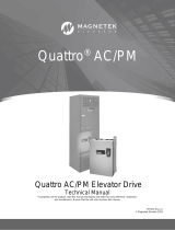
Figure 1: Interconnection Diagram
13
14
15
16
12
TB2
TB1
TB1
6
7
8
9
10
11
24
25
26
21
22
23
logic input 1
logic input 2
logic input 3
logic input 4
logic input 5
logic input 6
logic input 7
logic input 8
logic input 9
+24VDC isolated
logic input common
+24VDC iso. common
commcommoncommon
logic output 1
logic output 2
logic output 3
logic output 4
logic output common
analog input 2 (+)
analog input 2 (-)
shield
analog output 1
2
3
4
5
6
Speed Cmd
10VDC
PreTorque Cmd
10VDC
1
7
analog output 2
analog common
27
28
29
30
31
32
relay 1
relay 2
HPV 900
Axial Flux
input
power
R
S
T
17
18
1
2
3
4
19
20
encoder +12 VDC
encoder common
A
/A
B
/Z
/B
Z
TB2
9
Tx (+)
common
Rx (+)
Tx (-)
Rx (-)
5
shield
shield
8
analog input 1 (-)
B1
Dynamic Braking
Resistor
B2
-
dc bus (-)
dc bus (+)
+2
+1
optional DC choke
analog input 1 (+)
10
11
12
13
14
G
ground
ac
motor
U
V
W
motor
connections
Serial
Communication
Port
USB (Mag Explorer)
Connection
Refer to
Encoder
Electrical
Connection
on page 8
Refer to
Proximity
Switch
Sensor
Electrical
Connection
on page 8

Installation
6
Mechanical Mounting Instructions
The following parts need to be mounted on to the motor: proximity sensor (red device with 3 wires
coming out of it as shown in Figure 3), incremental encoder, rider wheel, sensor bracket, target, sticky
pad, and hex nuts.
Figure 2: Axial Flux Assembly Kit
Figure 3: Picture of Proximity Sensor (PN
05P00217-0097)
1. The rider wheel should be tightly fitted on
the incremental encoder’s shaft as shown
in Figure 4 with 2mm allen key (or a
Philips head screw driver depending on
the wheel type). It should be positioned so
that the wheel will sit on the center of the
exposed edge of the rotor. NOTE: if the
encoder shaft has a keying slot, do NOT
place any of the set screws in the keying
slots.
Figure 4: Incremental Encoder with the rider
wheel fitted on shaft
encoder
rider wheel

Installation
7
2. The proximity sensor should be loosely
fitted to the bracket with 2x M12 nut with
19mm wrench as shown in Figure 5.
Figure 5: Proximity sensor fasten on bracket
3. The sensor bracket and encoder should be
loosely mounted on the motor with socket
head cap screws with washers as shown
in Figure 6. NOTE: there should be a pre-
made encoder mount on the motor frame
to mount the rider wheel and encoder.
Make sure that the rubber on the rider
wheel is making good physical contact on
the rotor so that the wheel rotates with the
rotor.
Figure 6: Picture of encoder, proximity sensor,
and sensor bracket (PN 43T02814-0030)
4. Ascertain the correct location on the rotor
where the target is to be fitted and prepare
the surface by cleaning using the alcohol
pad provided. The target should be
positioned so that the shorter rounded face
of the target extends to line up with the
proximity sensor as shown in Figure 8.
Figure 7: Picture of the proximity targets (PN
43T02814-0018 REV 00)
Figure 8: Top view picture of the proximity
sensor and target
5. As a final adjustment, use the gap tool to
get the proximity sensor within 0.060in
[1.6mm] of the target as shown in Figure
10. The gap tool is 0.060in thick.
Figure 9: Gap tool (PN 43T02814-0020)
bracket
prox. sensor
encoder
bracket
prox. sensor
target
prox. sensor

Installation
8
Figure 10: Using gap tool to get the target into
the sensing range of the proximity sensor
6. Then tighten the nuts after the gap has
been met with a 19mm wrench and
remove the gap tool.
Encoder Electrical Connection
NOTE: Before connecting any encoder onto
the drive, make sure that the encoder can
operate at 12V
DC
because the power supply on
the drive will be 12V
DC
.
NOTE: The TerMag board part number
46S04284-0010 will not work on the Axial Flux
drive. The TerMag board used on the Axial
Flux is pn 46S04284-1020
The encoder cable has 3 twisted wire pairs.
The connection of the encoder to the drive is
shown in Figure 11.
Figure 11: Encoder Connection to Drive TB1
46S04284-1020 TerMag Board
Proximity Sensor Electrical
Connection
NOTE: The proximity sensor should ONLY be
used on TerMag board number 46S04284-
1020.
The proximity sensor cable should be wired up
to the drive as shown in Figure 12. When
connecting the cable to the proximity sensor,
latch the coupling ring on the female (cable
end) connector into its open position (rotate
the ring clockwise as you look into the sockets
of the connector). Then insert the male
(proximity sensor end) connector into the
female (cable end) connector. Finally, rotate
the coupling ring on the female connector in
the opposite direction until it latches into its
closed position.
Figure 12: Proximity Sensor Connection to Drive
TB1 46S04284-1020 TerMag Board
SW1: It is recommended that the 2 dip
switches for encoder channel filtering be
turned on (up position) for SW1 as shown in
Figure 13: SW1-2 is the filter for Z and SW1-3
is for A/B. SW1-1 is used to place a 120 ohm
terminating resistor across the receiver input
for serial communication; it should be in the on
position when serial cables longer than 50 feet
is being used.
SW2: The proximity sensor requires a 12V
DC
power supply. So if not already done, SW2 on
the TerMag Board should be set for the 12V
(right position) rather than the 5V power supply
(left position) as shown in Figure 13.
SW3: SW3 should also be configured so that
the A and B channels are set for differential
input and the Z channel is set for single ended
input as shown in Figure 13; starting from the
left: up, down, down, up, down, and up.
bracket
gap tool
target
prox. sensor
to Encoder
TB1
1
2
3
4
17
18
5
A
/A
/B
B
shield
+12V
DC
comm
/A
/B
COM
B
A
+VDC
shield
shield
Brwn
Blue
Black
COM
Z
NC
+VDC
V
CC
COM
Output
1
2
3
4
5
17
18
19
A
/A
B
/B
shield
encoder +12VDC
encoder common
Z
20
/Z
TB1
Proximity
Sensor

Installation
9
Figure 13: TerMag Board Switch Configuration
PM Drive Setup Procedure
1. Verify that the drive is in PM Mode for
Drive Mode in U9.
2. Enter the measured building voltage
going into the drive in the ‘Input L-L
Volts’ (A4)
3. Enter your motor data from the motor
nameplate into Sub-menu A5: Motor
ID, rated motor power, rated motor
volts, rated motor current, rated motor
poles, and rated motor speed.
a.
If your motor speed and motor
poles are entered correctly,
motor frequency on nameplate
and the ‘Rated Excit Freq’ in
the D2 sub-menu should be
the same
4. Setup both ‘Encoder Pulses’ and ‘Enc
PPR Low’ in the A1 sub-menu using
one of the following method: a
(preferred), b, or c.
NOTE: Encoder Pulses (A1) is set
higher than the PPR on the encoder
nameplate (in this case 1024 PPR)
because the encoder shaft is mounted
on a rider wheel that sits on the rotor;
1 revolution of the rider wheel doesn’t
equate to 1 revolution of the motor
a. Ropes off PPR (preferred):
i. with ropes removed
from/off sheave, perform
an Open Loop Alignment
on page 12.
ii. After the alignment, enter
the number in Measured
PPR (D1) into the Encoder
Pulses (A1).
iii. Then run the motor at
contract speed and look at
the Measured PPR (D1)
while motor is rotating at
contact speed with ropes
OFF
iv. The number in Measured
PPR (D1) while motor was
rotating at contract speed
should be entered to
Encoder Pulses (A1)
NOTE: if this is done, step
8 in PM Drive Setup
Procedure on page 10
doesn’t need to be done.
NOTE: Measured PPR
(D1) at high speed is more
accurate than at low speed.
b. Ropes on PPR estimate:
i. Select from Table 2 (page
10) the number of encoder
pulses that correspond to
the motor frame you have.
Enter that number as the
Encoder Pulses in the A1
menu
SW3
SW2
Switch
configuration
description
on board
Z
sing
A
diff
B
diff
12V
DC
5V
DC
SW1
1
2
3

Installation
10
PM Motor Frame
Types
Encoder Pulses (A1) /
Enc PPR Low (A1)
MX05/10
14395 PPR
MX05/16
14452 PPR
MX06/05
17067 PPR
MX06/10
17067 PPR
MX06/16
17067 PPR
MX10/05
19819 PPR
MX10/08
19735 PPR
MX10/10
19819 PPR
MX10/15
19680 PPR
MX20
12929 PPR
Elevator Motor
____
Table 2: Setting for A1 Encoder Pulses for
different motor types
c. Ropes on PPR calculation:
i. Mathematically calculate
the Encoder Pulses (A1)
using the equation below.
The diameter of the rider
wheel is either 37.3mm
(1.469in) or 75mm
(2.952in) depending on
which one you have.
5. Verify that both Encoder Pulses (A1)
and Enc PPR Low (A1) are set to the
same value for low speed operation
(such as the construction phase).
6. Before the motor can run, a rotor
alignment to find the motor poles
needs to be performed. The 3
methods to find the motor pole are:
High Frequency (HF) Injection, Open-
Loop Align, and Auto-Align beginning
on page 11 in PM Alignment
Procedure.
NOTE: HF injection is recommended
because it can locate the motor’s
poles more reliably on these motors
than Auto-Align.
7. Perform an auto-tune on the drive so
that the drive has a more accurate
motor model outlined in Auto-Tune
Procedure on page 15.
NOTE: skip step 8 if the motor was
running at high speed with ropes off
8. After the motor can run up/down the
hoist at high speed, fine tune the
Encoder Pulses (A1) and Enc PPR
Low (A1) by entering the number in
the D1 ‘Measured PPR’ into these
parameters.
NOTE: The number set in the Encoder
Pulses (A1) HAS to be the value
displayed in D1 ‘Measured PPR’ at
high speed. The number set in the Enc
PPR Low (A1) HAS to be the value
displayed in D1 ‘Measured PPR’ at low
speed.
Refer to Troubleshooting page 16 if
the drive faults out

Appendix – PM Alignment Procedure
11
PM Alignment Procedure
Before the motor can run, a rotor alignment to
find the motor poles needs to be performed.
The 3 method to find the poles are: High
Frequency (HF) Injection, Open-Loop Align,
and Auto-Align.
HF Inject (preferred method)
High Frequency Injection is a function that will
locate the poles without the need to spin the
motor. This procedure should be done with the
brakes set. This is especially useful for
replacing encoders. HF Inject may be enabled
two different ways, one way is to enable the
function through the operator and the other is
to enable HF Inject by giving the drive a run
command. In order for the function to properly
work, all faults must be cleared, the brake
must be set and the motor contactor must pull
in.
1. Press the RIGHT or LEFT arrow until you
see the U0 Utility menu as shown below.
2. Use the UP or DOWN arrow to navigate
through the U0 menu to the U10 sub-menu
as shown below.
3. Press Enter, then UP arrow until Alignment
method is shown. Press Enter, then the
UP arrow until HF Inject is shown. Then
press Enter to save the setting.
4. Press the DOWN arrow until ALIGNMENT
is displayed. Press Enter and UP arrow to
change the ALIGNMENT from DISABLE to
ENABLE then press Enter as shown
below.
5. Press the DOWN arrow to see BEGIN
ALIGNMENT.
Note: If the operator displays the screen
below, verify ALIGNMENT (U10) is set to
enable, there are no active faults (FAULT
LED is off), and the drive is not in a RUN
mode (RUN LED is off).
6. If YES is selected, the drive will
immediately start sending current to the
motor and calculate the alignment value.
NOTE: When using YES, make sure that
the contactor is closed before YES is
entered.
7. If ON RUN is selected, the drive expects
the following sequence to occur:
a. Car Controller asserts DRIVE ENABLE
b. Car Controller issues RUN Command
c. Drive asserts CLOSE_CONTACT (all
other outputs will stay false during the
Alignment excluding READY TO RUN
which will stay active)
d. Motor Contactor closes
e. Drive starts Alignment procedure with the
brakes set (not picked)
10:00 May 4
U0 UTILITY
U1 PASSWORD
READY
RUN
USER
TORQUE
LIMIT
FAULT
SUBMENU
DATA ENTRY
10:00 May 4
U0 UTILITY
U10 ALIGNMENT
READY
RUN
USER
TORQUE
LIMIT
FAULT
SUBMENU
DATA ENTRY
U10 10:00
Alignment Method
HF INJECT
READY
RUN
USER
TORQUE
LIMIT
FAULT
SUBMENU
DATA ENTRY
U10 10:00
ALIGNMENT
ENABLE
READY
RUN
USER
TORQUE
LIMIT
FAULT
SUBMENU
DATA ENTRY
U10 10:00
BEGIN ALIGNMENT?
NO
READY
RUN
USER
TORQUE
LIMIT
FAULT
SUBMENU
DATA ENTRY
U10 10:00
NOT AVAILABLE AT THIS
TIME
READY
RUN
USER
TORQUE
LIMIT
FAULT
SUBMENU
DATA ENTRY

Appendix – PM Alignment Procedure
12
During the Alignment, a loud high pitch beep will
come out of the motor and the RUN LED will be
lit for the duration of the procedure.
Open Loop Alignment
Open Loop Alignment is a function that will
locate the motor poles by spinning the motor.
This requires that the ropes be off the motor
sheave and that the brakes are lifted/picked
when performing the alignment. Open Loop
may be enabled two different ways, one way is
to enable the function through the operator and
the other is to enable it by giving the drive a
run command. In order for the function to
properly work, all faults must be cleared, the
brake must be picked and the motor contactor
must pull in.
1) In order to accurately measure the
alignment, the motor has to operate in a
no-load condition. This can be achieved by
removing the ropes from the sheave of the
motor
2) Press the RIGHT or LEFT arrow until the
U0 menu is displayed.
3) Press the UP or DOWN arrow in the U0
menu to find Alignment (U10) sub-menu.
Press ENTER, then the UP arrow to
display:
Verify ALIGNMENT METHOD is set to
OPEN LOOP.
Scroll to ALIGNMENT and press ENTER
to change parameter ALIGNMENT from
DISABLE to ENABLE. Press ENTER.
Press the DOWN arrow to start the
alignment procedure. The operator will
display:
Note: If the operator displays the following
screen, verify ALIGMENT (U10) is set to
enable, there are no active faults (FAULT
LED is off), and the drive is not in a RUN
mode (RUN LED is off).
Press ENTER to change the data from NO
to either YES or ON RUN.
Note: For either selection, any speed
command issued to the drive will be
ignored, however it may be necessary for
the car controller to anticipate the motor
moving at 1/8
th
rated motor speed (A5).
4) If YES is selected, the motor will
immediately start applying current to the
motor and calculating the alignment value.
5) If ON RUN is selected, the drive expects
the following items to occur:
a. Car Controller asserts DRIVE ENABLE
b. Car Controller issues Run Command
10:00 May 4
U0 UTILITY
U10 ALIGNMENT
READY
RUN
USER
TORQUE
LIMIT
FAULT
SUBMENU
DATA ENTRY
U10 10:00
Alignment Method
Open Loop
READY
RUN
USER
TORQUE
LIMIT
FAULT
SUBMENU
DATA ENTRY
U10 10:00
ALIGNMENT
ENABLE
READY
RUN
USER
TORQUE
LIMIT
FAULT
SUBMENU
DATA ENTRY
U10 10:00
BEGIN ALIGNMENT?
NO
READY
RUN
USER
TORQUE
LIMIT
FAULT
SUBMENU
DATA ENTRY
U10 10:00
NOT AVAILABLE AT THIS
TIME
READY
RUN
USER
TORQUE
LIMIT
FAULT
SUBMENU
DATA ENTRY
U10 10:00
BEGIN ALIGNMENT?
ON RUN
READY
RUN
USER
TORQUE
LIMIT
FAULT
SUBMENU
DATA ENTRY

Appendix – PM Alignment Procedure
13
c. Drive asserts SPD_REG_RLS and
CLOSE_CONTACT (all other outputs
will operate as programmed and have
no special status or benefit during the
Alignment Procedure)
d. Motor Contactor closes
e. Drive asserts BRAKE_PICKED, if used
f. Brake is lifted
g. Drive starts the Open Loop Alignment
running at approximately 1/8
th
of the
rated motor speed (A5)
h. When the Alignment is finished, the
drive will go to zero speed and simulate
removal of the run command (i.e. SPD
REG RLS = 0 (false); CLOSE
CONTACT = 0 (false)) even if Run
Command is still being asserted
i. Run Command is removed
During the test, the motor should rotate for
about four seconds and the RUN light will be lit
for the duration of the procedure.
Erratic movement of the motor may occur
during acceleration and deceleration
segments of the alignment, but constant
speed operation will be smooth. If the
motor is jerking as it is rotating, increase
the OL ALIGN SCALE (A5) by 0.5.
If the alarm SPD DEV ALM is displayed,
increase the value of SPD DEV ALARM
LVL (A1) then retry procedure to see what
fault the drive may actually be getting. The
SPD DEV ALM will not allow the alignment
procedure to finish and must be moved out
of the way to proceed.
If the fault SPD DEV FLT is displayed,
first, verify the shield of the encoder cable
is properly grounded. Then retry the
alignment procedure. If the fault still exists,
increase SPD DEV FLT LVL (A1), and
then retry alignment procedure.
If the fault OVERCURR FLT is displayed;
decrease ALIGN VLT FACTOR (A4)
and/or the OL ALIGN SCALE (A5) retry
alignment procedure
If ENCODER FAULT or TACH LOSS is
displayed, verify that the encoder is
working or that the brakes on the motor
are being picked.
6) View the value of ENCODER ANG
OFST(A5). If the value is 30000, the
alignment procedure did not work and
must be redone. If the, ENCODER ANG
OFST (A5) is 00000, the alignment
procedure passed.
7) Enter the value in ‘Measured PPR’ (D1)
into ‘Encoder Pulses’ (A1)
8) Run motor at 20% contract speed and
verify alignment is correct.
If ropes are not attached, set INERTIA
(A1) to 0.25 seconds
If the SPD DEV FLT occurs, check if
TORQ CURR (D2) is greater than 5%
(>5%). If this is the case, repeat the
alignment procedure.
9) Run the motor at 100% contract speed.
While the motor is running at contract
speed, make note of number in the
‘Measured PPR’ (D1).
10) Enter the ‘Measured PPR’ from above at
contract speed into ‘Encoder Pulses’ (A1)
Auto Alignment Procedure
Auto Alignment is a function that will calculate
the alignment angle without the need to spin
the motor. This procedure has to be done with
the brake set. This is especially useful for
replacing encoders. Auto Alignment may be
enabled two separate ways, one way is to
enable the function through the operator and
the other is to enable Auto Align by giving the
drive a run command. In order for the function
to properly work, all faults must be cleared
(FAULT LED is off), the brake must be set, and
the motor contactor must pull in.
NOTE: If HF Inject can be performed, it is
recommended that the HF Inject be performed
instead of the Auto Alignment because HF
Inject is more reliable.
1) In order to accurately measure the
alignment, the brake must be set and the
motor contactor must be closed.
Depending on the method used for
enabling Auto Alignment, drive signals
may be used in conjunction with the
contactor.
2) Run the Auto Alignment (U10) to
determine the position of the motor poles.
Press Enter, then the UP Arrow to display:
10:00 May 4
U0 UTILITY
U10 ALIGNMENT
READY
RUN
USER
TORQUE
LIMIT
FAULT
SUBMENU
DATA ENTRY

Appendix – PM Alignment Procedure
14
Verify ALIGNMENT METHOD is set to
AUTO ALIGN.
Scroll to ALIGNMENT and press Enter to
change parameter ALIGNMENT from
DISABLE to ENABLE. Press Enter.
Press the DOWN arrow to start the
alignment procedure. The Operator will
display:
Press Enter to change the data from NO to
either YES or ON RUN.
3) If YES is selected, the drive will
immediately start applying current to the
motor and calculate the alignment value.
NOTE: the motor contactor should be
manually pushed in BEFORE the ENTER
button is pressed.
4) If ON RUN is selected, the drive expects
the following sequence to occur:
f. Car Controller asserts DRIVE ENABLE
g. Car Controller issues RUN Command
h. Drive asserts CLOSE_CONTACT (all
other outputs will stay false during the
Alignment excluding READY TO RUN
which will stay active)
i. Motor Contactor closes
j. Drive starts the Alignment procedure
Note: If the operator displays the following
screen, verify ALIGNMENT (U10) is set to
enable, there are no active faults (FAULT
LED is off), and the drive is not in a RUN
mode (RUN LED is off).
During Alignment, a slight buzzing noise
should come from the motor for approximately
two seconds and the RUN light will be lit for
the duration of the procedure.
If the fault AT CONTACT FLT is displayed,
verify the motor contactor is closed
If the fault BRAKE IS OPEN is displayed,
the drive has detected motion, verify the
brake is set. If brake is set and minimal
movement has occurred, increase BRK
FLT LEVEL (A4).
When the Alignment is finished, the drive will
simulate the removal of the run command even
if Run Command is still being asserted.
U10 10:00
Alignment Method
AUTO ALIGN
READY
RUN
USER
TORQUE
LIMIT
FAULT
SUBMENU
DATA ENTRY
U10 10:00
ALIGNMENT
ENABLE
READY
RUN
USER
TORQUE
LIMIT
FAULT
SUBMENU
DATA ENTRY
U10 10:00
BEGIN ALIGNMENT?
NO
READY
RUN
USER
TORQUE
LIMIT
FAULT
SUBMENU
DATA ENTRY
U10 10:00
NOT AVAILABLE AT THIS
TIME
READY
RUN
USER
TORQUE
LIMIT
FAULT
SUBMENU
DATA ENTRY

Appendix – AutoTune Procedure
15
Auto-Tune Procedure
Auto-Tune is a function used only on PM (U9)
that will automatically calculate the D and Q
Axis Inductances and the Stator Resistance
based on the calculated value of the motor’s
Base Impedance. Auto-Tune may be enabled
two separate ways, one way is to enable the
function through the operator and the other is
to enable Auto-Tune by giving the drive a run
command. In order for the function to properly
work, all faults must be cleared, the brake
must be set and the motor contactor must pull
in.
Setting Auto-Tune
Note: Alignment Procedure should precede
this Auto-Tune function. Alignment will affect
the accuracy of the D and Q Axis Stator
Inductances.
1) In order to accurately measure the motor
parameters, the brake must be set and the
motor contactor must be closed.
Depending on the method used for
enabling Auto-Tune, drive signals may be
used in conjunction with the contactor
2) Scroll to AUTOTUNE SEL (U12) to run the
Auto-tune function. No Faults may be
present on the drive when engaging Auto-
Tune.
Press Enter to display:
Press Enter and use down arrow keys to
select ON RUN or YES to enable Auto-Tune
Note: The contactor needs to be in for Auto-
Tune to run. If necessary, manually hold the
contactor in while the test is running.
3) Press Enter to change the data from
DISABLE to either YES or ON RUN.
4) If the selection YES is made, the drive will
immediately start applying current to the
motor and calculate the motor
characteristics.
5) If the selection ON RUN is made, the drive
expects the following sequence to occur
prior to the drive applying current to motor:
Command run (inspection) on the car
controller. The speed command must be
set to zero (0) speed. The following
sequence must be observed by the car
controller to properly perform Auto-Tune
via Car Controller
a. Car Controller asserts DRIVE ENABLE
b. Car Controller issues RUN Command
c. Drive asserts CLOSE_CONTACT (all
other outputs will stay false during the
Auto-Tune)
d. Motor Contactor closes
e. Drive starts the Auto-Tune procedure
f. When the Auto-Tune is finished, the
drive will simulate the removal of the run
command even if Run Command is still
being asserted.
g. Run Command is removed
During Auto-Tune, a slight buzzing noise
should come from the motor for approximately
two seconds and the RUN LED will be lit for
the duration of the procedure.
If the fault CONTACTOR FLT is displayed,
verify the motor contactor is closed
If the fault BRAKE IS OPEN is displayed, the
drive has detected motion, verify the brake is
set. If brake is set and minimal movement has
occurred, increase BRK FLT LEVEL (A4).
The following parameters will populate:
a. D Axis Induct (A5)
b. Q Axis Induct (A5)
c. Stator Resist (A5)
10:00 May 4
U0 UTILITY
U12 AUTOTUNE SEL
READY
RUN
USER
TORQUE
LIMIT
FAULT
SUBMENU
DATA ENTRY
U12 10:00
Autotune Select
DISABLE
READY
RUN
USER
TORQUE
LIMIT
FAULT
SUBMENU
DATA ENTRY
U12 10:00
Autotune Select
ON RUN
READY
RUN
USER
TORQUE
LIMIT
FAULT
SUBMENU
DATA ENTRY
U12 10:00
ALARM!
AUTOTUNE IS DONE
READY
RUN
USER
TORQUE
LIMIT
FAULT
SUBMENU
DATA ENTRY

Appendix – Troubleshooting
16
Troubleshooting
This is just a short list of faults/alarm/difficulties
that can come up when starting up a HPV900
Series 2 Axial Flux drive ONLY.
NOTE: A more detailed fault list can be found
in the HPV900 Series 2 Technical Manual
TM7333.
Faults/Alarms/Difficulties
Description
Solutions
Encoder Flt
The drive is in a run condition
and the encoder is:
not functioning
or
not connected
or
phasing is not proper with
motor phasing
Incorrect Encoder Phasing
Verify that the encoder
phasing is correct
Swap encoder A and /A
channel on TB1-1 and TB1-
2
Perform an Open-Loop
Alignment
Encoder Power Supply
Check that the encoder
power supply on TB1-17
and TB1-18 is 12V
DC
Verify that SW2 is switched
to the 12V position (at
right). Verify that the
voltage between TB1-17
and TB1-18 is 12 volts DC
Parameter Settings
Verify that the Encoder
Connect (C1) is set to axial
flux
Verify that the Encoder
Pulses (A1) is set to a
reasonable number
Encoder Mechanical Setup
Verify that the rider wheel is
firmly on the rotor and that
the encoder spins as the
rotor is spinning
/