Page is loading ...

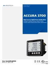
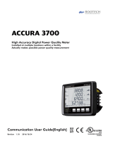
ACCURA 3700
High Accuracy Digital Power Quality Meter
Installed at multiple locations within a facility
Actually makes possible power quality measurement
User Guide[English]
Revision 1.17 2018/01/02

Digital Power Quality Meter
Accura 3700
Accura 3700 Rear
Extension Module
Accura 3700 DIO module Accura 3700 AI module Accura 3700 RTD module
Accura 3700 DI module Accura 3700 AO module Accura 3700 ELD module
Accura 3700 DO module Accura 3700 A4D2 module Accura 3700 DC module
Accura 3700 A2D4 module

Accura 3700 User Guide
Warranty Information
Notice
Symbol
Caution
Indicates the presence of dangerous voltage which can cause severe injury or
death to persons if proper precautions are not followed.
Warning
Alerts the user to the presence of hazards which can cause somewhat injury to
persons, damage to property or damage to the device itself, if proper precautions
are not followed.
Note
Indicates the user’s attention to installation, operating and maintenance
instructions.
Indicates alternative voltage or current.
Indicates direct voltage or current.
Installation Considerations
Installation and operation of Accura 3700 should be performed only by qualified, competent
personnel that have appropriate training and experience with high voltage and current devices.
Caution
Failure to observe the following instructions may result in severe injury or death.
During normal operation of the Accura 3700, hazardous voltages present on its terminal
strips of voltages input and power.
Standard safety precautions are followed while performing any installation or service work
[removing PT fuses, shorting CT secondary etc.].
Do not access to terminal strips of the Accura 3700 after installation.

Warranty Information
Accura 3700 User Guide
Warning
Observe the following instructions or permanent damage to the meter may occur.
Do not apply Accura 3700 to voltages and currents that exceed input ratings of PT and CT.
Manual
Rootech Inc. reserves the right to make changes in the device specifications shown in this User
Guide without notice. Rootech Inc. advises customers to obtain the latest specifications of device
before giving orders to confirm that the information being relied on by the customer is up to date.
In the absence of written agreement to the contrary, Rootech Inc. assumes no liability for Rootech
Inc. applications assistance, customer’s system design, or infringement of patents or copyrights of
third parties by or arising from the use of devices described herein.
The information contained in this document is believed to be accurate at the time of publication,
however, Rootech Inc. assumes no responsibility for any errors which may appear here and
reserves the right to make changes without notice.
Limitation of Liability
Where applicable law allows and does not prohibit or restrict such limitation, the Rootech, Inc’s
liability for anything relating to this product shall be limited to the price paid for the product.

Accura 3700 User Guide
Warranty Information
Warranty
For products and software that are sold or licensed by Rootech Inc. during the period from the
date of receipt by you until the present, Rootech warrants only to the original purchaser.
The purchased products shall be substantially free from material defects in material and
workmanship by Rootech for two years from the date receipt by you.
The software itself is provided “as is” without any warranty of any kind.
In order for the original purchaser to make a claim under the warranties described above, the
original purchaser must promptly contact Rootech headquarter. After receiving such notice,
Rootech may either in Rootech’s sole discretion, examine the product at the original purchaser’s
site or issue shipping instructions to the original purchaser to return the relevant product to
Rootech for examination at the original purchaser’s expense, transportation charges prepaid.
If after examining the product Rootech reasonably confirms that such examined product does not
meet the warranties, then the original purchaser’s sole remedy and Rootech’s sole obligation or
liability shall be, at Rootech’s option, to repair, replace or refund the price paid for that product.
Limitation of Warranty
The Warranty does not apply to uninterrupted or error-free operation of the Product or cover
normal wear and tear of the product or costs caused by the removal, installation, or
troubleshooting of the customer's electrical systems.
The warranty claims for defects caused by any of the following factors are not covered.
Improper use(alteration, accident, misuse, abuse) or Failure to act in accordance with
installation, operation or maintenance instructions
Unauthorized modifications, changes or attempted repairs
Failure to comply with applicable safety standards & regulations
Damages when transporting or storing
Damages by force majeure, examples are(not necessarily limited): fire, flood, earthquakes,
storm damage, overvoltage & lightning

Warranty Information
Accura 3700 User Guide
If the original identify markings(trade-mark, serial number, etc) have been defaced, altered,
or removed
Rootech shall not be liable for any other claim than a claim solely for the breach of one of the
above warranties that is made in accordance with the above described procedures- made by the
original purchaser, its employees, agents, or contractors for any loss, damage, or expense
incurred due to, caused by, or related to any purchased product.
Any technical assistance provided by Rootech's personnel or representatives in system design shall
be deemed to be a proposal and not a recommendation. The responsibility for determining the
feasibility of such proposals lies with the original purchaser and should be tested by the original
purchaser.
It is the original purchaser’s responsibility to determine the suitability of any product and
associated documentation for its purposes. The original purchaser acknowledges that 100% "up"
time is not realizable because of possible hardware or software defects. The original purchaser
recognizes that such defects and failures may cause inaccuracies or malfunctions.
Only the terms expressed in these limited Warranties shall apply and no distributor, corporation
or other entity, individual or employee of Rootech or any other entity is authorized to amend,
modify or extend the Warranties in any way

Accura 3700 User Guide
Notice
ⓒ 2013 Rootech Inc. All Rights Reserved Page 7
Standard Compliance
Process Control Equipment
E324900
MSIP-REM-RTE-ACCURA 3700
QMS-1347 KAB-QC-09

Revision History
Accura 3700 User Guide
Page 8 ⓒ 2013 Rootech Inc. All Rights Reserved
Revision History
The following versions of the Accura 3700 User Guide has been released.
Revision
Date
Description
Revision 1.0B 2013. 02. 22 Initial draft
Revision 1.10 2014. 01. 07 First revision
Revision 1.11 2014. 02. 05 AI modified
Revision 1.12 2014. 02. 18 Modified to IEC 61000-4-30, IEC 61000-4-7
Revision 1.13 2015. 05. 21 Standard Compliance updated
Revision 1.14 2015. 07. 13 10mm size modification updated[p29]
Revision 1.15 2016. 10. 24 Navigation bookmark added
Revision 1.16 2017. 09. 20 UL Certification code changed
Revision 1.17 2018. 01. 02 Notice, Warranty changed

Accura 3700 User Guide
Contents
ⓒ 2013 Rootech Inc. All Rights Reserved Page 9
Contents
Chapter 1 Introduction ................................................................................................................................... 14
Overview ................................................................................................................................................... 14
Application ............................................................................................................................................... 16
Device Lineup ........................................................................................................................................... 17
Features ................................................................................................................................................................................. 18
Chapter 2 Installation ..................................................................................................................................... 21
Environmental Conditions ...................................................................................................................... 21
Before you begin ..................................................................................................................................... 21
Meter Overview ................................................................................................................................................................. 21
Components ....................................................................................................................................................................... 25
Dimension ............................................................................................................................................................................ 26
Step 1: Panel Mounting .......................................................................................................................... 28
Accura 3700 Panel Mounting ..................................................................................................................................... 28
Step 2: Voltage/Current Wiring ............................................................................................................ 29
Step 3: Accura 3700 External Communication ................................................................................... 37
Ethernet Communication .............................................................................................................................................. 37
RS-485 Communication ................................................................................................................................................ 39
Step 4: Accura 3700 Power Supply/Ground ....................................................................................... 40
Power Supply ...................................................................................................................................................................... 40
Ground Terminal ............................................................................................................................................................... 40
Step 5: Accura 3700 Extension Module Addition .............................................................................. 41
Step 6: I/O Module ................................................................................................................................. 42
DIO Module ........................................................................................................................................................................ 42
DI Module ............................................................................................................................................................................ 45
DO Module .......................................................................................................................................................................... 47
AI Module ............................................................................................................................................................................ 49
AO Module .......................................................................................................................................................................... 50
A4D2/A2D4 Module........................................................................................................................................................ 51
RTD Module ........................................................................................................................................................................ 55
ELD Module......................................................................................................................................................................... 57
DC Module .......................................................................................................................................................................... 60
Chapter 3 Operation/Setup ........................................................................................................................... 64
LED .......................................................................................................................................................................................... 64
Button Function ................................................................................................................................................................ 64
Display Mode ........................................................................................................................................... 68
Front View ............................................................................................................................................................................ 68
Display Screen.................................................................................................................................................................... 70

Contents
Accura 3700 User Guide
Page 10 ⓒ 2013 Rootech Inc. All Rights Reserved
Measurement Parameter Display Screen .............................................................................................................. 71
Extension Module State View ..................................................................................................................................... 76
Display Screen for Classification of Extension Modules ............................................................................... 78
Event Mode .............................................................................................................................................. 85
Setup Mode .............................................................................................................................................. 93
Setup Menu ........................................................................................................................................................................ 94
METER Setup ...................................................................................................................................................................... 95
Event Setup ...................................................................................................................................................................... 103
RS-485 Communication Setup ............................................................................................................................... 109
ETHERNET Communication Setup ........................................................................................................................ 110
RESET Setup ..................................................................................................................................................................... 113
Display Setup .................................................................................................................................................................. 115
Extension Module ID Setup [MODULE] .............................................................................................................. 118
Individual Extension Module Setup ..................................................................................................................... 120
Module Setup Screen .................................................................................................................................................. 121
DI Module Setup
[dIDI]
......................................................................................................................................... 122
DO Module Setup
[doDO]
..................................................................................................................................... 123
DIO Module Setup
[dIoDIO]
............................................................................................................................... 128
AI Module Setup
[AI AI]
........................................................................................................................................ 128
AO Module Setup
[Ao AO]
.................................................................................................................................. 133
A4D2 Module Setup [MODULE]
[A4d2 A4D2]
............................................................................................. 136
A2D4 Module Setup
[A2d4A2D4]
.................................................................................................................... 137
RTD Module Setup
[rtdRTD]
............................................................................................................................... 138
ELD Module Setup
[ELdELD]
............................................................................................................................... 141
DC Module Setup
[dCDC]
.................................................................................................................................... 145
Information
[INFOInformation]
.......................................................................................................................... 154
Required Configuration Step .............................................................................................................. 155
Accura 3700 Voltage Wiring, PT Rating Configuration .............................................................................. 155
APPENDIX A Specification .......................................................................................................................... 158
APPENDIX B Standard Compliance ........................................................................................................... 160
APPENDIX C Accuracy/Reliability .............................................................................................................. 161
Accuracy ............................................................................................................................................................................. 161
Reliability ........................................................................................................................................................................... 162
APPENDIX D Ordering Information........................................................................................................... 163
INDEX .............................................................................................................................................................. 164

Accura 3700 User Guide
Figures
ⓒ 2013 Rootech Inc. All Rights Reserved Page 11
Figures
Fig 2.1 Accura 3700 Front ............................................................................................................................................ 21
Fig 2.2 Accura 3700 Side .............................................................................................................................................. 21
Fig 2.3 Accura 3700 Rear ............................................................................................................................................. 22
Fig 2.4 Accura 3700 DIO Module ............................................................................................................................ 23
Fig 2.5 Accura 3700 DI Module ................................................................................................................................ 23
Fig 2.6 Accura 3700 DO Module .............................................................................................................................. 23
Fig 2.7 Accura 3700 AI Module ................................................................................................................................ 23
Fig 2.8 Accura 3700 AO Module .............................................................................................................................. 23
Fig 2.9 Accura 3700 A4D2 Module ......................................................................................................................... 23
Fig 2.10 Accura 3700 A2D4 Module....................................................................................................................... 24
Fig 2.11 Accura 3700 RTD Module.......................................................................................................................... 24
Fig 2.12 Accura 3700 ELD Module .......................................................................................................................... 24
Fig 2.13 Accura 3700 DC Module ............................................................................................................................ 24
Fig 2.14 Accura 3700 Components ......................................................................................................................... 25
Fig 2.15 I/O Module Components........................................................................................................................... 25
Fig 2.16 Accura 3700 Front Dimension ................................................................................................................. 26
Fig 2.17 Accura 3700 Rear Dimension................................................................................................................... 26
Fig 2.18 Accura 3700 Side Dimension ................................................................................................................... 26
Fig 2.19 Accura 3700 I/O Module ........................................................................................................................... 26
Fig 2.20 Accura 3700 Mounting[ANSI 4”] ............................................................................................................ 28
Fig 2.21 Accura 3700 Mounting[DIN96] ............................................................................................................... 28
Fig 2.22 Voltage/Current Wiring ............................................................................................................................... 29
Fig 2.23 3 Phase 4 Wire 3PT, 3CT Wiring, Wiring Mode[CONN] = 3P4U ........................................... 31
Fig 2.24 3 Phase 3 Wire 2PT 3CT Wiring, Wiring Mode[CONN] = 3P3U ............................................ 32
Fig 2.25 3 Phase 3 Wire 2PT, 2CT wiring, Wiring Mode[CONN] = 3P3U ............................................ 32
Fig 2.26 1 Phase 3 Wire 2PT 2CT Wiring, Wiring Mode[CONN] = 1P3U ............................................ 33
Fig 2.27 1 Phase 2 Wire 1PT 1CT Wiring, Wiring Mode[CONN] = 1P2U ............................................ 33
Fig 2.28 3 Phase 4 Wire Direct 3CT Wiring, Wiring Mode[CONN] =3P4U ......................................... 34
Fig 2.29 3 Phase 3 Wire Voltage Direct 3CT Wiring, Wiring Mode[CONN]=3P3U ......................... 34
Fig 2.30 3 Phase 3 Wire Voltage Direct 2CT Wiring, Wiring Mode[CONN]=3P3U ......................... 35
Fig 2.31 1 Phase 3 Wire Voltage Direct 2CT Wiring, Wiring Mode[CONN]=1P3U ......................... 35
Fig 2.32 1 Phase 3 Wire Voltage Direct 1CT Wiring, Wiring Mode[CONN]=1P2U ......................... 36
Fig 2.33 Accura 3700 Ethernet Communication Port ..................................................................................... 37
Fig 2.34 Accura 3700 Ehternet Connection ........................................................................................................ 38

Figures
Accura 3700 User Guide
Page 12 ⓒ 2013 Rootech Inc. All Rights Reserved
Fig 2.35 Accura 3700 RS-485 Communication .................................................................................................. 39
Fig 2.36 Accura 3700 RS-485 Communication Connection ........................................................................ 39
Fig 2.37 Accura 3700 Power Supply ....................................................................................................................... 40
Fig 2.38 I/O Module Addition.................................................................................................................................... 41
Fig 2.39 DIO Module ...................................................................................................................................................... 42
Fig 2.40 Digital Input (Dual Input Structure) ...................................................................................................... 43
Fig 2.41 DC Relay Application ................................................................................................................................... 44
Fig 2.42 AC Relay Application .................................................................................................................................... 44
Fig 2.43 DI Module ......................................................................................................................................................... 45
Fig 2.44 Digital Input (Dual Input Structure) ...................................................................................................... 46
Fig 2.45 DO Module ....................................................................................................................................................... 47
Fig 2.46 DC Relay Application ................................................................................................................................... 48
Fig 2.47 AC Relay Application .................................................................................................................................... 48
Fig 2.48 AI Module .......................................................................................................................................................... 49
Fig 2.49 Analog Input .................................................................................................................................................... 49
Fig 2.50 AO Module ....................................................................................................................................................... 50
Fig 2.51 AO Module Analog Output ...................................................................................................................... 50
Fig 2.52 A4D2 Module .................................................................................................................................................. 51
Fig 2.53 A2D4 Module .................................................................................................................................................. 51
Fig 2.54 A4D2/A2D4 Module Analog Output .................................................................................................... 52
Fig 2.55 DC Relay Application ................................................................................................................................... 53
Fig 2.56 AC Relay Application .................................................................................................................................... 54
Fig 2.57 RTD Module ..................................................................................................................................................... 55
Fig 2.58 RTD Input ........................................................................................................................................................... 56
Fig 2.59 ELD Module ...................................................................................................................................................... 57
Fig 2.60 ELD Input ........................................................................................................................................................... 57
Fig 2.61 DC Relay Application ................................................................................................................................... 59
Fig 2.62 AC Relay Application .................................................................................................................................... 59
Fig 2.63 DC Module ........................................................................................................................................................ 60
Fig 2.64 DC Voltage/Current ...................................................................................................................................... 60
Fig 2.65 Digital Input(Dual Input Structure) ........................................................................................................ 61
Fig 2.66 DC Relay Application ................................................................................................................................... 63
Fig 2.67 AC Relay application .................................................................................................................................... 63
Fig 3.1 Accura 3700 Front Composition ............................................................................................................... 64
Fig 3.2 DISPLAY Mode Screen Example ................................................................................................................ 65
Fig 3.3 SETUP Mode Screen Example .................................................................................................................... 65

Accura 3700 User Guide
Figures
ⓒ 2013 Rootech Inc. All Rights Reserved Page 13
Fig 3.4 Event Mode Screen Example ...................................................................................................................... 66
Fig 3.5 Accura 3700 Front Overview ...................................................................................................................... 68
Fig 3.6 First Screen of Display Mode ..................................................................................................................... 71
Fig 3.7 Voltage/Current/Power Display Screen for Each Phase................................................................. 71
Fig 3.8 Line to Line Voltage Specific Measurement Value Display Screen .......................................... 72
Fig 3.9 Line to Neutral Current Specific Measurement Value Display Screen ................................... 72
Fig 3.10 Power Specific Measurement Value Display Screen ..................................................................... 73
Fig 3.11 Demand Active Power Specific Measurement Value Display Screen ................................... 73
Fig 3.12 NET Energy Display Screen in Energy Display Screen ................................................................. 74
Fig 3.13 Ethernet Connection State Display Screen ........................................................................................ 74
Fig 3.14 Temperature Display Screen in ETC Display Screen ..................................................................... 75
Fig 3.15 First Screen Displaying ID of the Extension Module .................................................................... 76
Fig 3.16 Display Screen of Extension Module[Ex: DIO module] in Module Screen ........................ 76
Fig 3.17 Display Screen of the Second Extension Module in Module Screen................................... 77
Fig 3.18 DIO Module First Screen ............................................................................................................................ 79
Fig 3.19 DI Module First Screen ............................................................................................................................... 80
Fig 3.20 DO Module First Screen ............................................................................................................................. 80
Fig 3.21 AI Module First Screen ............................................................................................................................... 81
Fig 3.22 AO Module First Screen ............................................................................................................................. 82
Fig 3.23 A4D2 Module First Screen ........................................................................................................................ 82
Fig 3.24 A2D4 Module First Screen ........................................................................................................................ 83
Fig 3.25 RTD Module First Screen ........................................................................................................................... 83
Fig 3.26 ELD Module First Screen ............................................................................................................................ 84
Fig 3.27 DC Module First Screen.............................................................................................................................. 84
Fig 3.28 Dip[Sag] Event Alarm Screen ................................................................................................................... 85
Fig 3.29 Swell Event Alarm Screen .......................................................................................................................... 85
Fig 3.30 Event Log Number Example ..................................................................................................................... 87
Fig 3.31 Demand Measuring Method .................................................................................................................... 97
Fig 3.32 Power Sign[General Calculation] ............................................................................................................ 98
Fig 3.33 Difference between Two Methods that Calculate Each Phase Sum Power ................... 100
Fig 3.34 Dip Event Setup[3P3U] ............................................................................................................................. 105
Fig 3.35 Dip Event Setup[3P4U] ............................................................................................................................. 105
Fig 3.36 Swell Event Setup[3P3U] ......................................................................................................................... 107
Fig 3.37 Swell Event Setup[3P4U] ......................................................................................................................... 107

Chapter 1 Introduction
Accura 3700 User Guide
Page 14 ⓒ 2013 Rootech Inc. All Rights Reserved
Chapter 1 Introduction
Overview
Advent of Power Quality Management Era of Switchgear Panel
Due to the problems of power supply, power facility, and load, various power quality problems
such as Dip[Sag]/Swell are often generated in a moment at switchgear panel. Finding the cause
of problems by the power quality analysis, energy management supervisor has to make proper
preventive or post steps.
0.2% Reading/IEC62053-22 Class 0.2S Accuracy
Recently enterprise energy management system establishment is required for effective energy use
and preventive management to prepare CO2 emission management in plant, factory and
building. The key factor to determine reliability of energy management is the degree of measuring
accuracy of power meter. Accura 3700 performs 0.2% high accuracy measurements for voltage
and current, and conforms to IEC62053-22 class 0.2S for power and energy. This makes it
possible to precisely analyze and diagnose various problems with energy management and power
facilities.
True RMS Measurement
Accura 3700 performs 128 sampling/cycle True RMS measurement for the high non-linear loads.
Dip[Sag]/Swell[IEC61000-4-30 Class A], Power Quality
Accura 3700 provides various power quality information such as Dip[Sag], Swell, harmonic
information[up to 63 harmonics], Crest factor, K-factor, and unbalance. This makes it possible for
energy management supervisor to easily find the power quality change in the power facility.
Quality information conforms to IEC61000-4-30.
Aggregation Interval Maximum/Minimum/Average Information
Accura 3700 provides the average value that corresponds to 0.2 second interval from the
measurement value by cycle unit. Based on 0.2 second interval average value, Accura 3700
provides the average of 1 second, 5 seconds, 1 minute, 5 minutes, 1 hour and 6 hours intervals.
This measurement interval that is longer than 0.2 second means the aggregation interval.
Accura 3700 provides not only the 0.2 second interval average value of measurement parameter,
but also statistic data(maximum/minimum/average) of voltage, current and power by

Accura 3700 User Guide
Chapter 1 Introduction
ⓒ 2013 Rootech Inc. All Rights Reserved Page 15
communication. As this includes the data measurement parameter which changes in a moment,
this makes it possible to do accurate trend analysis for voltage, current and power quality.
CE, UL, KCC, FCC Safety and Reliability
The structure[framework, circuit, fire] of Accura 3700 conforms to standard, CE[EN61326-1,
EN61326-2-1], UL[UL61010-1], KCC[KN22, KN24], FCC[Part15 Subpart B].
Additional Function Provision by Module Extension Structure at the Rear of Meter
Module extension structure that the modules are easily added to the rear of Accura 3700
physically can flexibly handle with the additional function requirement. Modules are options and
provide various functions such as digital input/output, digital input, digital output, analog input,
analog output, analog/pulse output, RTD input, leakage current measurement and DC
measurement per each type. Modules can be added up to three modules regardless of order and
the same module can be selected. But AO module can be added up to two.

Chapter 1 Introduction
Accura 3700 User Guide
Page 16 ⓒ 2013 Rootech Inc. All Rights Reserved
Application
High-Reliability Energy Management
Energy management is specified into various application services such as power quality
management, cost management, demand power management, power facility replacement, and
energy plan connecting with upper level program. The most important thing that decides the data
reliability of energy management is the accuracy degree of digital meter. As Accura 3700
performs Reading 0.2% high-accuracy measurement for voltage and current, and power/energy
conforms to the compliance IEC62053-22 Class 0.2S, it enables construction of accurate energy
management system.
Preventive/Post Measures for Power Facility Operation Management
Accura 3700 provides various functions like energy usage management, power facility
management, power quality management and high-efficiency facility analysis management. This
enables energy management supervisor to make proper preventive or post measures by
suggesting accurate analytical standard of judgement for power usage and quality.
Enterprise Energy Management
Accura 3700 mounted on various switchgear panels in the power facilities and Accura
2300[2300S]/2350 mounted on branch loads inside the distribution panel provide the power
quality information which is essential for energy management. This realizes the true enterprise
energy management system by total-measuring the power receiving-based switchgear panels and
power usage-based distribution panels.

Accura 3700 User Guide
Chapter 1 Introduction
ⓒ 2013 Rootech Inc. All Rights Reserved Page 17
Device Lineup
Accura 3700 is high-accurate power quality meter which has Dip/Swell detecting functions of
IEC61000-4-30, and harmonic wave analysis up to 63 harmonics with accurate power
measurement functions of IEC62053-22 Class 0.2S.
Also, Accura 3700 provides various I/O functions which can increase the field availability. I/O
function is provided by the module structure adding to the rear of Accura 3700 and various
modules are provided corresponding to the composition of I/O channels. The modules can be
added up to three regardless of order, and the same module can be selected. But AO module can
be added up to two.
Device
Model
Description
Power Quality Meter Accura 3700 Voltage/ current/power measurement
Power quality measurement
For both Ethernet[supports star, daisy chain, ring connection]
and RS-485 communication
Temperature in distribution panel 1
Digital I/O Module DIO DI 8 channels, DO 2 channels 2
DI DI 12 channels
DO DO 6 channels 2
Analog I/O Module AI AI 6 channels
AO AO 6 channels 3
Digital and Analog A4D2 AO 4 channels 3 + DO 2 channels 2
I/O Module A2D4 AO 2 channels 3 + DO 4 channels 2
Special-purpose Module RTD RTD input 3 channels
Supports PT100, PT1000
Supports 2-Wire, 3-Wire, 4-Wire
ELD Uses voltage-type ZCT
Leakage current input 6 channels, DO 1channel 2
DC DC voltage input 1 channel, DC current input 2 channels, DI
4 channels, DO 1 channel 2
1 It is not for firewatching, but for reference only[A temp sensor is positioned on the side of Accrua 3700].
2 DO channel supports the ON/OFF output[Latch], pulse, periodic pulse and energy pulse.
3 AO channels outputs various electricity amount or command value of communication by converting as 0 ~
20mA.

Chapter 1 Introduction
Accura 3700 User Guide
Page 18 ⓒ 2013 Rootech Inc. All Rights Reserved
Features
Accura 3700 Power Quality Meter
Accura 3700 performs 0.2% Reading accurate measurement for voltage and current,
power/energy conforms to IEC62053-22 Class 0.2S. Also it provides various information such as
Dip[Sag], Swell, harmonics, Crest factor, K-factor, unbalance, etc. which is essential for power
quality management of switchgear panels.
Accura 3700
Function
Measurement
Display
Realtime measurement data LCD display
Analog graphic display corresponding to the measurement
amount
General
Sampling/cycle 128
Commercial frequency 50/60Hz
True RMS measurement Voltage, current: Reading
0.2%
Frequency 42 ~ 69Hz
Neutral current[I
n
]2
Demand, peak demand, prediction demand 1, 2
Maximum, minimum
Maximum 2, minimum2, average2 in the aggregation
interval 3
Energy
kWh/kVarh received, kWh/kVarh delivered IEC62053-22 Class 0.2S
kWh/kVarh net[kWh/kVarh received - kWh/kVarh delivered] IEC62053-22 Class 0.2S
kWh/kVarh sum[kWh/kVarh received + kWh/kVarh
delivered]
IEC62053-22 Class 0.2S
Power Quality
Voltage/current harmonics information Up to 63 harmonics
Voltage/Current THD4, current TDD5 Up to 63 harmonics
Crest factor 6, 2, K-factor 7, 2
Dip[Sag], Swell IEC61000-4-30
Unbalance[voltage, current] 2 IEC61000-4-30, NEMA
MG1
Vector diagram 2
Harmonic analysis graph[voltage, current] 2
Oscilloscope 2
Demand trend 2
Event
Dip[Sag], Swell event detection Half cycle moving 1-
cycle RMS Measuring
Digital Input, analog input event detection8 1msec
Number of Event Log Up to 500

Accura 3700 User Guide
Chapter 1 Introduction
ⓒ 2013 Rootech Inc. All Rights Reserved Page 19
Extension Module Addition
Number of IO Modules which can be added to the rear of
meter
Up to 3EA, 2EA(AO)
Temperature
Temperature in the distribution panel 9 1EA
Communication
Ethernet [100Mbps/Full Duplex, Ethernet switching 10, RSTP11,
Modbus TCP protocol]
2 ports[Ethernet1,
Ethernet2]
RS-485[1,200 ~ 115,200bps, Modbus RTU protocol] 1 port [Ta, Tb]
General
UL certification UL61010-1
CE certification EN61326-1, EN61326-
2-1
FCC certification Part15 Subpart B
KCC certification KN22, KN24
AC Power AC 85 ~ 265V
DC Power DC 100 ~ 300V
1 Calculates the prediction demand power supposing the power of present point in the demand interval to be
the same for the remaining interval.
2 Data can be achieved by not be displayed on LCD and only by the communication.
3 Accura 3700 provides statistic data of maximum, minimum, average for voltage, current power by
communication. As this includes the data of measurement parameter which changes in a moment, this
performs accurate trend-analysis for about voltage, current and power quality.
4 THD[Total harmonic distortion]. Voltage THD:
, Current THD:
5 TDD[Total demand distortion]. Current TDD:
But, can be done by the configuring default current or Peak demand current [through communication].
6 Crest factor:
, 7 K-factor: (
)
8 Available when the module is mounted.
9 It is not for firewatching, but for reference only[A temp sensor is positioned on the side of Accrua 3700].
10 As Ethernet switch is built-in, Accura 3700 Ethernet connection is available among Accura 3700s without
the extra external switch.
11 RSTP[Rapid Spanning Tree Protocol], IEEE 802.1D-2004

Chapter 1 Introduction
Accura 3700 User Guide
Page 20 ⓒ 2013 Rootech Inc. All Rights Reserved
I/O Module
Accura 3700 provides various modules can be physically easily added on the rear of meter as an
option. Modules can be added up to three regardless of order, and the same module can be
selected. But AO module can be added up to two.
I/O Module
Feature
Model
Channel
Specification
DIO module Digital Input 8 channels Dry Contact, dualization
Digital Output 2 channels AC/DC 400V 350mA[max. 1A] 3
DI module Digital Input 12channels Dry Contact, dualization
DO module Digital Output 6 channels AC/DC 400V 350mA[max. 1A] 3
AI module Analog Input 6 channels DC 0 ~ 20mA
AO module Analog Output 6 channels DC 4 ~ 20mA, DC 0 ~ 20mA
A4D2 module Analog Output 4 channels DC 4 ~ 20mA, DC 0 ~ 20mA
Pulse Output 2 channels AC/DC 400V 350mA[max. 1A] 3
A2D4 module Analog Output 2 channels DC 4 ~ 20mA, DC 0 ~ 20mA
Pulse Output 4 channels AC/DC 400V 350mA[max. 1A] 3
RTD module RTD Input 3 channels PT100, PT1000 4,3,2 line form
ELD module LeakCurrent Input 6 channels AC 0 ~ 2,000mA
Digital Output 1 channel AC/DC 400V 350mA[max. 1A] 3
DC module DC Voltage Input 1 channel 0 ~ 200V
DC Current Input 2 channels 0 ~ 100mV[Shunt Needed]
Digital Input 4 channels Dry Contact, dualization
Digital Output 1 channels AC/DC 400V 350mA[max. 1A] 3
Operation
Digital Input Detecting Period 1msec
Analog Input Detecting Period 1msec
Analog output [Measurement
Connected] Controlling Period 200msec
Analog output [Communication
Connected] Controlling Period 20msec
General
UL Certification UL61010-1
CE Certification EN61326-1, EN61326-2-1
FCC Certification Part15 Subpart B
KCC Certification KN22, KN24
Power Supply Accura 3700
1 Digital output supports the ON/OFF output, single pulse output, periodic pulse output and energy pulse
output.
2 Analog output outputs electricity amount measured at the device or command value of communication by
converting as 0 ~ 20mA.
3 Peak AC / DC value, and max 1A current is energizing cycle 100ms one-shot current.
/