Crestron MP-WP152 User manual
- Category
- Motorcycle Accessories
- Type
- User manual

Crestron MP-WP Series
Media Presentation Wall Plates
Installation Guide
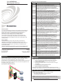
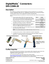
Media Presentation Wall Plates complete the total Crestron
®
package, ensuring
end-to-end Crestron quality for every installation. A range of wall plates is offered to
support all types of analog and digital video, audio, and control signals.
The wall plates are 1-gang standard electrical box mountable; fit off-the-shelf decorative
face plates; can be ganged for custom wall, lectern, and rack mount applications; and
are available in black, white, or almond.
DESCRIPTION
Typical Application (MP-WP130 Shown)
Crestron Electronics, Inc. Installation Guide - DOC. 6881B
15 Volvo Drive Rockleigh, NJ 07647 (2025165)
Tel: 888.CRESTRON 04.11
Fax: 201.767.7576 Specifications subject to
www.crestron.com change without notice.
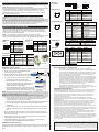
MODEL
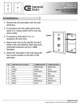
MP-WP100 Three gold-plated RCA connectors, color-coded and labeled for
composite video and stereo audio. Bulkhead type feed-thru
connectors are used, providing female RCA connections at the rear.
MP-WP110 One gold-plated 4-pin mini-DIN connector and two gold-plated RCA
connectors, color-coded and labeled for S-video and stereo audio.
Bulkhead type feed-thru connectors are used, providing female mini-DIN
and RCA connections at the rear.
MP-WP120 Five gold-plated RCA connectors, color-coded and labeled for
component video and stereo audio. Bulkhead type feed-thru
connectors are used, providing female RCA connections at the rear.
MP-WP125 Eight gold-plated RCA connectors, color-coded and labeled for separate
component and composite video and stereo audio. Bulkhead type feed-thru
connectors are used, providing female RCA connections at the rear.
MP-WP130 One female DB15HD connector (i.e., HD-15, DE-15) and one 1/8" mini-TRS
connector, labeled for computer VGA and stereo audio. A bulkhead type
feed-thru connector is used, providing a female DB15HD connection at the
rear. Audio wiring is connected via a 3-pin terminal block.
MP-WP131 One female DB15HD connector (i.e., HD-15, DE-15) and one 1/8"
mini-TRS connector, labeled for computer VGA and stereo audio.
A 12" breakout cable assembly at the rear provides five BNC
connections. Audio wiring is connected via a 3-pin terminal block.
MP-WP140 One Dual Link DVI-I connector and one 1/8" mini-TRS connector,
labeled for DVI and stereo audio. A bulkhead type feed-thru
connector is used, providing a female DVI-I connection at the rear.
Audio wiring is connected via a 3-pin terminal block.
MP-WP150 One Type A HDMI
®
connector and one 1/8" mini-TRS connector, labeled for
HDMI and stereo audio. A bulkhead type feed-thru connector is used,
providing a female HDMI connection at the rear. Audio wiring is connected
via a 3-pin terminal block.
MP-WP152 One Type A HDMI
connector. A bulkhead type feed-thru connector
is used, providing a female HDMI connection at the rear.
MP-WP160 One DisplayPort connector and one 1/8" mini-TRS connector, labeled for
DisplayPort and stereo audio. A bulkhead type feed-thru connector is used,
providing a female DisplayPort connection at the rear. Audio wiring is
connected via a 3-pin terminal block.
MP-WP162 One DisplayPort connector. A bulkhead type feed-thru connector is
used, providing a female DisplayPort connection at the rear.
MP-WP180 One female 8-pin RJ-45 connector, and one 4-pin 3.5mm detachable
terminal block, labeled for QuickMedia
®
and Cresnet
®
, respectively.
Bulkhead type connectors are used, providing a female RJ-45 and
detachable terminal block connections at the rear.
MP-WP181 One female 8-pin RJ-45 connector labeled for DigitalMedia 8G
™
. Punch-down
terminals at the rear facilitate installation using DM-CBL-8G DigitalMedia 8G
Cable.
MP-WP183 One female 8-pin RJ-45 connector labeled for Ethernet. A bulkhead type
connector is used, providing a female RJ-45 connection at the rear.
MP-WP185 Two female 8-pin RJ-45 connectors, and one 4-pin 3.5mm detachable
terminal block, labeled for DigitalMedia
™
. A combination of punch-down and
screw terminal connections at the rear of the wall plate facilitate installation
using DM-CBL DigitalMedia Cable.
MP-WP186 Two female SC type optical fiber connectors, labeled for DigitalMedia.
Bulkhead type feed-thru connectors are used, providing female SC
connections at the rear, for installation using CresFiber
®
Fiber Optic Cable
or equivalent.
MP-WP187 A single female SC type optical fiber connector, labeled for DigitalMedia.
Bulkhead type feed-thru connector are used, providing female SC
connection at the rear, for installation using CresFiber Fiber Optic Cable
or equivalent.
MP-WP190 One 4-pin 3.5mm detachable terminal block, labeled for Cresnet control.
A paralleled terminal block connection is provided at the rear.
DESCRIPTION
Media Presentation Wall Plate Models
AUDIO
PC
AUDIO
AUDIO
RGB
RGB
Further Inquiries
If you cannot locate specific information or have questions after reviewing this
guide, please take advantage of Crestron's award winning customer service
team by calling Crestron at 1-888-CRESTRON [1-888-273-7876]. For
assistance in your region, please refer to the Crestron Web site
(www.crestron.com) for a listing of Crestron worldwide offices.
You can also log onto the online help section of the Crestron Web site
(www.crestron.com/onlinehelp) to ask questions about Crestron products.
First-time users will need to establish a user account to fully benefit from all
available features.
Future Updates
As Crestron improves functions, adds new features and extends the
capabilities of the MP-WP Series, additional information may be made
available as manual updates. These updates are solely electronic and serve
as intermediary supplements prior to the release of a complete technical
documentation revision.
Check the Crestron Web site periodically for manual update availability and its
relevance. Updates are identified as an “Addendum” in the Download column.
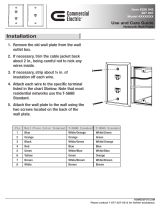
INSTALLATION
Installation of the Media Presentation Wall Plates consists of the following:
1. Select an appropriate wall plate location (wall, furniture, rack panel).
2. Using the supplied template, cut a hole in the mounting surface.
3. Install required electrical box*.
4. Run and terminate cables. Refer to the wiring information on this page
as necessary.
5. Test cables prior to screwing down the wall plate.
6. Screw the wall plate to the electrical box.
7. Attach face plate to the mount
ing surface.
* Electrical box not included. 3-1/2" (89 mm) extra-deep electrical box or mud-ring
recommended. Some cables and connectors may necessitate additional mounting depth.
NETWORK WIRING GUIDELINES
Cresnet
®
. When wiring the Cresnet network, consider the following:
• Use Crestron Certified Wire.
• Use Crestron power supplies for Crestron equipment.
• Provide sufficient power to the system.
CAUTION: Insufficient power can lead to unpredictable results or damage to the
equipment. Use the Crestron Power Calculator to help calculate how much power is
needed for the system. (www.crestron.com/calculators).

Refer to the following diagrams and instructions for specific wiring requirements.
24 A B G
Return and Warranty Policies
Merchandise Returns / Repair Service
1. No merchandise may be returned for credit, exchange or service without prior
authorization from CRESTRON. To obtain warranty service for CRESTRON products,
contact an authorized CRESTRON dealer. Only authorized CRESTRON dealers may
contact the factory and request an RMA (Return Merchandise Authorization) number.
Enclose a note specifying the nature of the problem, name and phone number of
contact person, RMA number and return address.
2. Products may be returned for credit, exchange or service with a CRESTRON Return
Merchandise Authorization (RMA) number. Authorized returns must be shipped freight
prepaid to CRESTRON, 6 Volvo Drive, Rockleigh, N.J. or its authorized subsidiaries,
with RMA number clearly marked on the outside of all cartons. Shipments arriving
freight collect or without an RMA number shall be subject to refusal. CRESTRON
reserves the right in its sole and absolute discretion to charge a 15% restocking fee
plus shipping costs on any products returned with an RMA.
3. Return freight charges following repair of items under warranty shall be paid by
CRESTRON, shipping by standard ground carrier. In the event repairs are found to be
non-warranty, return freight costs shall be paid by the purchaser.
CRESTRON Limited Warranty
CRESTRON ELECTRONICS, Inc. warrants its products to be free from manufacturing defects in
materials and workmanship under normal use for a period of three (3) years from the date of
purchase from CRESTRON, with the following exceptions: disk drives and any other moving or
rotating mechanical parts, pan/tilt heads and power supplies are covered for a period of one (1)
year; touchscreen display and overlay components are covered for 90 days; batteries and
incandescent lamps are not covered.
This warranty extends to products purchased directly from CRESTRON or an authorized
CRESTRON dealer. Purchasers should inquire of the dealer regarding the nature and extent of the
dealer's warranty, if any.
CRESTRON shall not be liable to honor the terms of this warranty if the product has been used in
any application other than that for which it was intended or if it has been subjected to misuse,
accidental damage, modification or improper installation procedures. Furthermore, this warranty
does not cover any product that has had the serial number altered, defaced or removed.
This warranty shall be the sole and exclusive remedy to the original purchaser. In no event shall
CRESTRON be liable for incidental or consequential damages of any kind (property or economic
damages inclusive) arising from the sale or use of this equipment. CRESTRON is not liable for any
claim made by a third party or made by the purchaser for a third party.
CRESTRON shall, at its option, repair or replace any product found defective, without charge for
parts or labor. Repaired or replaced equipment and parts supplied under this warranty shall be
covered only by the unexpired portion of the warranty.
Except as expressly set forth in this warranty, CRESTRON makes no other warranties, expressed
or implied, nor authorizes any other party to offer any warranty, including any implied warranties of
merchantability or fitness for a particular purpose. Any implied warranties that may be imposed by
law are limited to the terms of this limited warranty. This warranty statement supersedes all
previous warranties.
Crestron, the Crestron logo, CresFiber, Cresnet, DigitalMedia, DigitalMedia 8G, and QuickMedia are
trademarks or registered trademarks of Crestron Electronics, Inc. in the United States and other
countries. HDMI and High-Definition Multimedia Interface are trademarks or registered trademarks of
HDMI Licensing LLC in the United States and other countries. Other trademarks and trade names may
be used in this document to refer to either the entities claiming the marks and names or their products.
Crestron disclaims proprietary interest in the marks and names of others.
©2011 Crestron Electronics, Inc
.
NETWORK WIRING GUIDELINES (Continued)
PREPARING AND CONNECTING WIRES
Strip the ends of the wires approximately 1/2" (13 mm). Use care to avoid nicking the
conductors. Twist together the ends of the wires that share a connection and tin the
twisted connection. Apply solder only to the ends of the twisted wires. Avoid tinning too
far up the wires or the end becomes brittle.
NOTE: It is not necessary to strip and tin wires for punch-down connection.
DM Network. When wiring the DM network, consider the following:
NOTE: DMNet wiring and Cresnet wiring are not compatible.
For DigitalMediaCAT wiring, use DM-CBL or DM-CBL-8G DigitalMedia
™
cable, as
required. For complete wiring guidelines, refer to the latest revision of the Crestron
DigitalMedia Design Guide (Doc. 4789) which is available from the Crestron Web site
(www.crestron.com/dmresources).
QuickMedia. When wiring the QuickMedia network, consider the following:
NOTE: Do not untwist pairs of wires more than 1/3-1/2” (8-12 mm) when making a
connection. The twists are critical to canceling out interference between the wires.
The aggregate cable length of a signal path originating at a QM transmitter and
terminating at a QM receiver must not exceed 450 feet (137 meters).
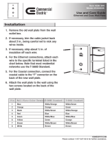
S-Video Wiring
QuickMedia Wiring
1 8
VGA Wiring
1
11
10
5
6
15
1 Red Video
2 Green Video
3 Blue Video
4 Reserved
5 Ground
6 Red Ground
7 Green Ground
8 Blue Ground
PIN # SIGNAL PIN # SIGNAL
9 No Connection
10 Ground
11 No Connection
12 Monitor Sense
13 Horizontal Sync
14 Vertical Sync
15 Monitor Sense Clock
24 +24V Red
A Data Orange
B Data Grey
G Ground Black &
Stranded
PIN # SIGNAL WIRE
COLOR
24 Y Z G
1
White/Orange
2 Orange
3
White/Green
4 Blue
PIN # WIRE COLOR PIN # WIRE COLOR
5
White/Blue
6 Green
7 White/Brown
8 Brown
1
3
4
2
RJ-45 PIN
NUMBER
WIRE COLORS
(EIA 568B)
QM ASSIGNMENT:
RGB
6 4
3 5
8 2
7 1
Sleeve
Tip
Ring
L G R
T S R
Mini-TRS
Connections
1 8
1 Luminance Ground
2 Chrominance Ground
PIN # DESCRIPTION
3 Luminance
4 Chrominance
PIN # DESCRIPTION
Ethernet Wiring
RJ-45 Punch
Down Wiring
Cresnet Port
Wiring
DMNet Port
Wiring
1
White/Orange - RGB Red
2 Orange
+ RGB Red
3
White/Green - RGB Green
4 Blue
+ Digital Audio
5
White/Blue - Digital Audio
6 Green
+ RGB Green
7 White/Brown
- RGB Blue
8 Brown
+ RGB Blue
24 +24V Red
Y Data White
Z Data Blue
G Ground Black
PIN # SIGNAL WIRE
COLOR
6 Green
3
White/Green
8 Brown
7 White/Brown
PIN # WIRE COLOR
(EIA 568B)
4 Blue
5
White/Blue
2 Orange
1
White/Orange
Ground Clamp
Shield Cover
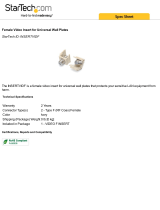
DigitalMedia Cable Termination
Terminate the DM-CBL DigitalMedia cable to the supplied interface connectors as follows:
1. Strip 6 inches (153 mm) of the DigitalMedia Cable
to expose the three inner cables.
2. For the 'D' cable, strip the outer jacket 1 3/4 inch
(45 mm) from the end. Gather and twist the braid.
a. Trim the foil shield to 1/2 inch (13 mm) and fold it
back against the outer jacket of the cable.
b. Remove the white inner jacket and separate the
twisted pairs to expose the spline. Cut the spline so
that it is near flush with the outer jacket. Return the
twisted pairs to their original position.
c. Fold the foil shield back to its original position over the
wire pairs. Neatly wrap the twisted braid around the foil
shield. Only the silver
side of the foil shield is conductive.
NOTE: The braid should wind neatly around the foil shield. Loose braid may cause shorts
or difficulty completing assembly of the connector.
NOTE: Do not allow the twisted pairs to untwist for more than 1/2 inch (13 mm).
d. Remove the shield cover from one of the supplied RJ-45 connectors. Place the
CAT5/6 'D' cable so the area with the braid wrapped around the shield foil is
positioned within the connector's ground clamp.
e. Starting with the terminals closest to the ground clamp, insert the twisted pairs and
use a 110 tool to push them down. Refer to the above table for pin/color
assignments.
f. If the 110 tool does not do so, trim the ends flush with the sides of the terminals;
crimp the ground clamp over the cable shield, and replace the connector shield
cover.
3. For the 'M' cable, strip the ou
ter jacket 1 3/4 inch (45 mm) from the end. Place the
cable on the RJ-45 connector so the end of the outer jacket is positioned within the
connector's ground clamp.
4. Repeat steps 2e and 2f for the 'M' cable, except crimp the ground clamp over the
outer jacket to secure the cable in position.
5. For the DMNet cable, terminate the wires to the supplied 4-pin terminal block
connector as shown in the DMNet Port Wiring table above.
DigitalMedia 8G Cable Termination
Terminate the DM-CBL-8G DigitalMedia cable following the same procedures as given for
the DM-CBL 'D' cable in step 2 above, except for step 2b, since there is no inner jacket or
spline.
Twisted Wire
Braid
1 3
/4 in
(45 mm)
1/2 in
(
13 mm
)
Fold Foil Over Jacket
Cut Spline Here
PIN # WIRE COLOR
(EIA 568B)
-
 1
1
-
 2
2


Crestron MP-WP152 User manual
- Category
- Motorcycle Accessories
- Type
- User manual
Ask a question and I''ll find the answer in the document
Finding information in a document is now easier with AI
Related papers
-
Crestron PWR-IT-M Installation guide
-
-
-
-
-
-
-
-
-
Other documents
-
 Commercial Electric 216 8C User guide
-
 Cables Direct 2TT-15 Datasheet
-
 Crestron electronic DM-CONN-20 User manual
-
 Commercial Electric 216 8C Operating instructions
-
AudioQuest 3886010045 Datasheet
-
 Commercial Electric 217F 8C WH Installation guide
-
 Commercial Electric B4684CW002 User manual
-
 StarTech.com INSERTVIDF Datasheet
-
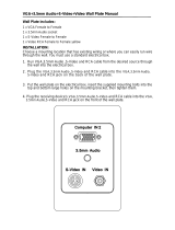 Wintal VGA+3.5mm Audio+S-Video+Video User manual
-
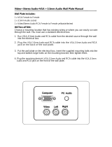 Wintal Video+ Stereo Audio+VGA + 3.5mm Audio User manual


