Extron MLS 608 D User manual
- Category
- Supplementary music equipment
- Type
- User manual

User Guide
MLS 608 D SERIES
AV SWITCHERS
AV Switchers with ProDSP
™
(with the MTP/HDMI U R receiver)
68-1893-01 Rev. A
12 11
MTP/HDMI U R
MLS 608 D SA

Precautions
This symbol is intended to alert the user of important operating and maintenance
(servicing) instructions in the literature provided with the equipment.
This symbol is intended to alert the user of the presence of uninsulated dangerous
voltage within the product’s enclosure that may present a risk of electric shock.
Caution
Read Instructions • Read and understand all safety and operating instructions before using the equipment.
Retain Instructions • The safety instructions should be kept for future reference.
Follow Warnings • Follow all warnings and instructions marked on the equipment or in the user information.
Avoid Attachments • Do not use tools or attachments that are not recommended by the equipment
manufacturer because they may be hazardous.
Warning
Power sources • This equipment should be operated only from the power source indicated on the product. This
equipment is intended to be used with a main power system with a grounded (neutral) conductor. The third
(grounding) pin is a safety feature, do not attempt to bypass or disable it.
Power disconnection • To remove power from the equipment safely, remove all power cords from the rear of the
equipment, or the desktop power module (if detachable), or from the power source receptacle (wall plug).
Power cord protection • Power cords should be routed so that they are not likely to be stepped on or pinched by
items placed upon or against them.
Servicing • Refer all servicing to qualified service personnel. There are no user-serviceable parts inside. To prevent
the risk of shock, do not attempt to service this equipment yourself because opening or removing covers may
expose you to dangerous voltage or other hazards.
Slots and openings • If the equipment has slots or holes in the enclosure, these are provided to prevent
overheating of sensitive components inside. These openings must never be blocked by other objects.
Lithium battery • There is a danger of explosion if battery is incorrectly replaced. Replace it only with the same or
equivalent type recommended by the manufacturer. Dispose of used batteries according to the manufacturer’s
instructions.
Ce symbole sert à avertir l’utilisateur que la documentation fournie avec le
matériel contient des instructions importantes concernant l’exploitation et la
maintenance (réparation).
Ce symbole sert à avertir l’utilisateur de la présence dans le boîtier de l’appareil
de tensions dangereuses non isolées posant des risques d’électrocution.
Attention
Lire les instructions• Prendre connaissance de toutes les consignes de sécurité et d’exploitation avant d’utiliser
le matériel.
Conserver les instructions• Ranger les consignes de sécurité afin de pouvoir les consulter à l’avenir.
Respecter les avertissements • Observer tous les avertissements et consignes marqués sur le matériel ou
présentés dans la documentation utilisateur.
Eviter les pièces de xation • Ne pas utiliser de pièces de fixation ni d’outils non recommandés par le fabricant
du matériel car cela risquerait de poser certains dangers.
Avertissement
Alimentations• Ne faire fonctionner ce matériel qu’avec la source d’alimentation indiquée sur l’appareil. Ce
matériel doit être utilisé avec une alimentation principale comportant un fil de terre (neutre). Le troisième
contact (de mise à la terre) constitue un dispositif de sécurité : n’essayez pas de la contourner ni de la
désactiver.
Déconnexion de l’alimentation• Pour mettre le matériel hors tension sans danger, déconnectez tous les cordons
d’alimentation de l’arrière de l’appareil ou du module d’alimentation de bureau (s’il est amovible) ou encore de
la prise secteur.
Protection du cordon d’alimentation • Acheminer les cordons d’alimentation de manière à ce que personne ne
risque de marcher dessus et à ce qu’ils ne soient pas écrasés ou pincés par des objets.
Réparation-maintenance • Faire exécuter toutes les interventions de réparation-maintenance par un technicien
qualifié. Aucun des éléments internes ne peut être réparé par l’utilisateur. Afin d’éviter tout danger
d’électrocution, l’utilisateur ne doit pas essayer de procéder lui-même à ces opérations car l’ouverture ou le
retrait des couvercles risquent de l’exposer à de hautes tensions et autres dangers.
Fentes et orices • Si le boîtier de l’appareil comporte des fentes ou des orifices, ceux-ci servent à empêcher les
composants internes sensibles de surchauffer. Ces ouvertures ne doivent jamais être bloquées par des objets.
Lithium Batterie • Il a danger d’explosion s’ll y a remplacment incorrect de la batterie. Remplacer uniquement
avec une batterie du meme type ou d’un ype equivalent recommande par le constructeur. Mettre au reut les
batteries usagees conformement aux instructions du fabricant.
Safety Instructions • English
Consignes de Sécurité • Français
Sicherheitsanleitungen • Deutsch
Dieses Symbol soll dem Benutzer in der im Lieferumfang enthaltenen
Dokumentation besonders wichtige Hinweise zur Bedienung und Wartung
(Instandhaltung) geben.
Dieses Symbol soll den Benutzer darauf aufmerksam machen, daß im Inneren
des Gehäuses dieses Produktes gefährliche Spannungen, die nicht isoliert sind
und die einen elektrischen Schock verursachen können, herrschen.
Achtung
Lesen der Anleitungen • Bevor Sie das Gerät zum ersten Mal verwenden, sollten Sie alle Sicherheits-und
Bedienungsanleitungen genau durchlesen und verstehen.
Aufbewahren der Anleitungen • Die Hinweise zur elektrischen Sicherheit des Produktes sollten Sie
aufbewahren, damit Sie im Bedarfsfall darauf zurückgreifen können.
Befolgen der Warnhinweise • Befolgen Sie alle Warnhinweise und Anleitungen auf dem Gerät oder in der
Benutzerdokumentation.
Keine Zusatzgeräte • Verwenden Sie keine Werkzeuge oder Zusatzgeräte, die nicht ausdrücklich vom Hersteller
empfohlen wurden, da diese eine Gefahrenquelle darstellen können.
Vorsicht
Stromquellen • Dieses Gerät sollte nur über die auf dem Produkt angegebene Stromquelle betrieben werden.
Dieses Gerät wurde für eine Verwendung mit einer Hauptstromleitung mit einem geerdeten (neutralen) Leiter
konzipiert. Der dritte Kontakt ist für einen Erdanschluß, und stellt eine Sicherheitsfunktion dar. Diese sollte nicht
umgangen oder außer Betrieb gesetzt werden.
Stromunterbrechung • Um das Gerät auf sichere Weise vom Netz zu trennen, sollten Sie alle Netzkabel aus der
Rückseite des Gerätes, aus der externen Stomversorgung (falls dies möglich ist) oder aus der Wandsteckdose
ziehen.
Schutz des Netzkabels • Netzkabel sollten stets so verlegt werden, daß sie nicht im Weg liegen und niemand
darauf treten kann oder Objekte darauf- oder unmittelbar dagegengestellt werden können.
Wartung • Alle Wartungsmaßnahmen sollten nur von qualiziertem Servicepersonal durchgeführt werden. Die
internen Komponenten des Gerätes sind wartungsfrei. Zur Vermeidung eines elektrischen Schocks versuchen
Sie in keinem Fall, dieses Gerät selbst öffnen, da beim Entfernen der Abdeckungen die Gefahr eines
elektrischen Schlags und/oder andere Gefahren bestehen.
Schlitze und Öffnungen • Wenn das Gerät Schlitze oder Löcher im Gehäuse aufweist, dienen diese zur
Vermeidung einer Überhitzung der empndlichen Teile im Inneren. Diese Öffnungen dürfen niemals von
anderen Objekten blockiert werden.
Litium-Batterie • Explosionsgefahr, falls die Batterie nicht richtig ersetzt wird. Ersetzen Sie verbrauchte Batterien nur
durch den gleichen oder einen vergleichbaren Batterietyp, der auch vom Hersteller empfohlen wird. Entsorgen
Sie verbrauchte Batterien bitte gemäß den Herstelleranweisungen.
Este símbolo se utiliza para advertir al usuario sobre instrucciones importantes
de operación y mantenimiento (o cambio de partes) que se desean destacar en
el contenido de la documentación suministrada con los equipos.
Este símbolo se utiliza para advertir al usuario sobre la presencia de elementos
con voltaje peligroso sin protección aislante, que puedan encontrarse dentro
de la caja o alojamiento del producto, y que puedan representar riesgo de
electrocución.
Precaucion
Leer las instrucciones • Leer y analizar todas las instrucciones de operación y seguridad, antes de usar el
equipo.
Conservar las instrucciones • Conservar las instrucciones de seguridad para futura consulta.
Obedecer las advertencias • Todas las advertencias e instrucciones marcadas en el equipo o en la
documentación del usuario, deben ser obedecidas.
Evitar el uso de accesorios • No usar herramientas o accesorios que no sean especificamente recomendados
por el fabricante, ya que podrian implicar riesgos.
Advertencia
Alimentación eléctrica • Este equipo debe conectarse únicamente a la fuente/tipo de alimentación eléctrica
indicada en el mismo. La alimentación eléctrica de este equipo debe provenir de un sistema de distribución
general con conductor neutro a tierra. La tercera pata (puesta a tierra) es una medida de seguridad, no
puentearia ni eliminaria.
Desconexión de alimentación eléctrica • Para desconectar con seguridad la acometida de alimentación eléctrica
al equipo, desenchufar todos los cables de alimentación en el panel trasero del equipo, o desenchufar el
módulo de alimentación (si fuera independiente), o desenchufar el cable del receptáculo de la pared.
Protección del cables de alimentación • Los cables de alimentación eléctrica se deben instalar en lugares donde
no sean pisados ni apretados por objetos que se puedan apoyar sobre ellos.
Reparaciones/mantenimiento • Solicitar siempre los servicios técnicos de personal calicado. En el interior no
hay partes a las que el usuario deba acceder. Para evitar riesgo de electrocución, no intentar personalmente la
reparación/mantenimiento de este equipo, ya que al abrir o extraer las tapas puede quedar expuesto a voltajes
peligrosos u otros riesgos.
Ranuras y aberturas • Si el equipo posee ranuras o orificios en su caja/alojamiento, es para evitar el
sobrecalientamiento de componentes internos sensibles. Estas aberturas nunca se deben obstruir con otros
objetos.
Batería de litio • Existe riesgo de explosión si esta batería se coloca en la posición incorrecta. Cambiar esta batería
únicamente con el mismo tipo (o su equivalente) recomendado por el fabricante. Desachar las baterías usadas
siguiendo las instrucciones del fabricante.
Instrucciones de seguridad • Español
安全须知 • 中文
这个符号提示用户该设备用户手册中有重要的操作和维护说明。
这个符号警告用户该设备机壳内有暴露的危险电压,有触电危险。
注意
阅读说明书 • 用户使用该设备前必须阅读并理解所有安全和使用说明。
保存说明书 • 用户应保存安全说明书以备将来使用。
遵守警告 • 用户应遵守产品和用户指南上的所有安全和操作说明。
避免追加 • 不要使用该产品厂商没有推荐的工具或追加设备,以避免危险。
警告
电源 • 该设备只能使用产品上标明的电源。 设备必须使用有地线的供电系统供电。 第三条线(
地线)是安全设施,不能不用或跳过 。
拔掉电源 • 为安全地从设备拔掉电源,请拔掉所有设备后或桌面电源的电源线,或任何接到市电
系统的电源线。
电源线保护 • 妥善布线, 避免被踩踏,或重物挤压。
维护 • 所有维修必须由认证的维修人员进行。 设备内部没有用户可以更换的零件。为避免出现触
电危险不要自己试图打开设备盖子维修该设备。
通风孔 • 有些设备机壳上有通风槽或孔,它们是用来防止机内敏感元件过热。 不要用任何东西
挡住通风孔。
锂电池 • 不正确的更换电池会有爆炸的危险。必须使用与厂家推荐的相同或相近型号的电池。按
照生产厂的建议处理废弃电池。

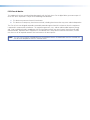
FCC Class A Notice
This equipment has been tested and found to comply with the limits for a Class A digital device, pursuant to part 15
of the FCC Rules. Operation is subject to the following two conditions:
1. This device may not cause harmful interference.
2. This device must accept any interference received, including interference that may cause undesired operation.
The Class A limits are designed to provide reasonable protection against harmful interference when the equipment
is operated in a commercial environment. This equipment generates, uses, and can radiate radio frequency energy
and, if not installed and used in accordance with the instruction manual, may cause harmful interference to radio
communications. Operation of this equipment in a residential area is likely to cause harmful interference, in which
case the user will be required to correct the interference at his own expense.
NOTE: This unit was tested with shielded cables on the peripheral devices. Shielded cables must be used with the
unit to ensure compliance with FCC emissions limits.
.

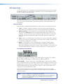
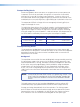
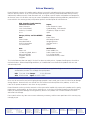
Conventions Used in this Guide
In this user guide, the following are used:
NOTE: A note draws attention to important information.
TIP: A tip provides a suggestion to make working with the application easier.
CAUTION: A caution indicates a potential hazard to equipment or data.
WARNING: A warning warns of things or actions that might cause injury, death, or
other severe consequences.
Commands are written in the fonts shown here:
^AR Merge Scene,,Op1 scene 1,1 ^B 51 ^W^C
[01] R 0004 00300 00400 00800 00600 [02] 35 [17] [03]
E X! *X1&* X2)* X2#* X2! CE}
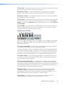
NOTE: For commands and examples of computer or device responses mentioned
in this guide, the character “0” is used for the number zero and “O”
represents the capital letter “o.”
Computer responses and directory paths that do not have variables are written in the font
shown here:
Reply from 208.132.180.48: bytes=32 times=2ms TTL=32
C:\Program Files\Extron
Variables are written in slanted form as shown here:
ping xxx.xxx.xxx.xxx —t
SOH R Data STX Command ETB ETX
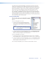
Selectable items, such as menu names, menu options, buttons, tabs, and field names are
written in the font shown here:
From the File menu, select New.
Click the OK button.
Copyright
© 2011 Extron Electronics. All rights reserved.
Trademarks
All trademarks mentioned in this guide are the properties of their respective owners.

PRELIMINARY
PRELIMINARY
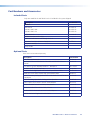
Contents
Introduction............................................................ 1
MLS 608 D Series Description .............................. 1
Features .............................................................. 1
Controlling the MLS 608 D Series Switcher ......... 3
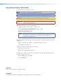
MLS 608 D SA Application Diagram
......................................................................... 4
Installation .............................................................. 5
UL/Safety Requirements ...................................... 5
Mounting the MLS 608 D Series Switchers .......... 6
Tabletop Placement ......................................... 6
UL Guidelines for Rack Mounted Devices ....... 6
Rack Mounting ............................................... 6
Rear Panel Connections ....................................... 7
MLS 608 D Series Rear Panel Features ................. 7
Power, Analog, and Digital Connections .......... 8
Audio and RS-232 Connections .................... 14
MTP/HDMI U R Connections ............................. 17
Power Save Mode ......................................... 19
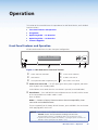
Operation .............................................................. 20
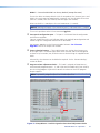
Front Panel Features and Operation .................. 20
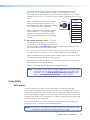
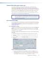
Using EDIDs ...................................................... 22
EDID Minder ................................................. 22
Automatic EDID Mode (digital output only) ... 24
User Assigned EDID Mode ............................. 24
Importing EDID Data ..................................... 25
Exporting EDID Data .................................... 25
Updating the EDID Table ............................... 26
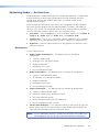
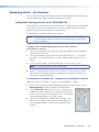
Optimizing Audio — An Overview .................... 27
Workspaces .................................................. 27
DSP Signal Chain .......................................... 28
Building Blocks — An Overview .................... 31
Group Masters — An Overview ..................... 35
Optimizing Video — An Overview ..................... 40
Setting the Peaking and Level on
the MTP/HDMI U R ....................................... 40
Setting the Skew on the MLS 608 D .............. 41
Selecting the MLS 608 D Output PrePeak ...... 41
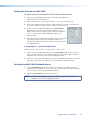
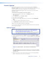
Firmware Upgrades ........................................... 42
Updating Firmware ....................................... 42
DSP Configurator
™
............................................. 44
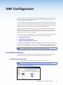
Installing the Software ...................................... 44
Installation From the DVD ............................. 44
Installation from the Website ........................ 45
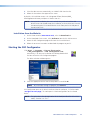
Starting the DSP Configurator ........................... 45
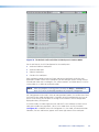
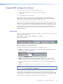
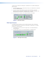
Using the DSP Configurator Software ............... 47
Orientation ................................................... 47
Workspace Menus ........................................ 48
MTP Video Settings ....................................... 57
HDCP Compliance ........................................ 59
Video Signal Presence ................................... 60
SIS Programming and Control .......................... 61
Host to MLS 608 D Communications ................ 61
MLS 608 D Switcher-initiated Messages ........ 61
Error Responses............................................. 62
Error Response References ............................ 62
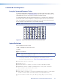
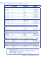
Command and Responses ................................. 63
Using the Command/Response Tables ........... 63
Symbol Definitions ........................................ 63
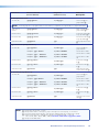
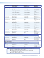
Command Response Table for SIS Commands ... 69
User Interface Navigation ................................. 77
Mouse and Keyboard Navigation ...................... 77
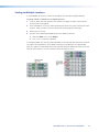
Selecting Multiple Blocks ............................... 77
Selecting Multiple Areas ................................ 77
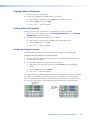
Copying a Block of Elements ......................... 78
Cutting a Block of Elements .......................... 78
Pasting to a Single Location .......................... 78
Pasting to Multiple Locations ........................ 79
Keyboard Shortcuts ........................................... 80
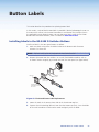
Button Labels ....................................................... 82
Installing Labels in the MLS 608 D
Switcher Buttons ............................................. 82
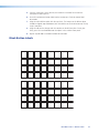
Blank Button Labels .......................................... 83
Reference Material ............................................. 84
Part Numbers and Accessories ........................... 92
Included Parts ............................................... 92
Optional Parts ............................................... 92
MLS 608 D Series • Contents v

MLS 608 D Series • Contents vi

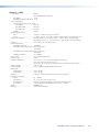
Introduction
This manual contains information about the Extron MLS 608 D Series of AV switchers with
instructions for experienced installers on how to install, configure, and operate it.
In this manual the terms “MLS 608 D Series switcher,” “AV switcher,” and “switcher” are
used interchangeably and refer to any of the MLS 608 D Series models.
MLS 608 D Series Description
The MLS 608 D AV switchers are available in three models:
z MLS 608 D — a non-amplified model with variable preamp outputs.
z MLS 608 D SA — features 2-channel stereo power amplification with 20 watts rms
per channel into 4 or 8 ohms.
z MLS 608 D MA — features mono 70 volt amplification with 40 watts rms output.
The MLS 608 D series are simple-to-use, eight input, multi-format switchers designed to
integrate digital and analog sources. All signals are transmitted over CAT 5-type cable to
the included MTP/HDMI U R Twisted Pair Receiver. The MLS 608 D Series feature Extron
ProDSP
™
digital audio processing, which provides an extensive array of easy-to-use
tools for audio system setup and fine-tuning. The MLS 608 D Series offers digital video
switching with four HDCP-compliant HDMI inputs, and analog video switching with four
universal inputs, including an Extron universal MTP twisted pair input. It outputs HDMI
twisted pair signals and analog MTP Twisted Pair to the included MTP/HDMI U R receiver,
providing a complete digital and analog video and audio switching system.
The MLS 608 D AV switchers are ideal for classrooms and other AV environments that
require the flexibility to integrate digital and analog video switching in a single switcher.
Features
z Inputs: Three 15-pin HD connectors – one with loop-through – for RGBHV, HDTV
component video, and S-video or composite video; one universal MTP twisted
pair input, four HDMI connectors; seven captive screw connectors for balanced or
unbalanced stereo audio; one balanced or unbalanced mono audio input via MTP
z Outputs:
MLS 608 D switcher — One buffered output on VGA connector (tied only to
input 1), two balanced or unbalanced audio outputs on captive screw connectors,
analog MTP video and audio output on one RJ-45 connector, digital video and
RS-232 on two RJ-45 connectors, one power amplifier output ( MA and SA models
only).
MTP/HDMI U R receiver — RGB on 15-pin HD, component video on BNCs, S-video
on 4-pin mini DIN, composite video on BNC, HDMI connector, balanced or unbalanced
audio on one captive screw connector, communications on a captive screw connector.
z Multi-input switcher for digital and analog video signals
z Transmits HDMI and analog video plus audio and RS-232 over CAT 5-type cables.
z Includes MTP/HDMI U R Twisted Pair Receiver — Automatically routes incoming
signals to the appropriate output connectors.
MLS 608 D Series • Introduction 1

z EDID Minder
®
— Automatically manages EDID – Extended Display Identication Data
– communication between the display and connected VGA and HDMI input sources.
EDID Minder ensures that all sources power up correctly and reliably output content,
whether or not they are actively connected to the display device through the switcher
outputs.
z HDMI audio de-embedding — Strips two-channel PCM audio off HDMI inputs,
allowing for DSP processing and signal routing.
z HDCP compliance — The MLS 608 D switchers and the included MTP/HDMI U R
device fully support switching and long distance transmission of HDCP signals.
z Cable equalization for each HDMI input — Actively conditions incoming HDMI
signals to compensate for signal loss when using long HDMI cables, low quality HDMI
cables, or source devices with poor HDMI signal output.
z Sends 720p, 1080i, and XGA (1024x768) HDMI signals up to 200 feet
(60 meters), 1080p/60 and 1920x1200 HDMI signals up to 100 feet (30 meters)
with standard CAT 5e cable — Extron STP201 Digital Twisted Pair cable provides
added protection from outside interference and increases overall signal transmission
distance.
z Four input analog universal video switching — Four universal inputs, including
an Extron universal MTP twisted pair, accept RGBHV, HDTV component video, and
S-video or composite video sources. The output is universal MTP twisted pair to the
included MTP/HDMI U R.
z Controllable (via TouchLink
™
Control System, MediaLink
®
Controller, front
panel buttons, or RS-232) — The switchers can be controlled using the front panel
backlit buttons or RS-232. An optional TouchLink Touchpanel Control System or
MediaLink Controller may be connected to the RS-232 port to provide a simple and
intuitive user interface for the MLS 608 D Switchers, and the entire room.
z Skew equalization for MTP input and output — Skew adjustments are stored in
memory for the MTP input and output, to maintain RGB color alignment at all times.
z Separate variable level and peaking controls for analog MTP signals
z Front panel control with backlit buttons — The buttons can be custom-labeled for
easy identication. Because the buttons illuminate, they are helpful for presenters in
low-light environments.
z Audio switching and output volume control — The MLS 608 D Series features
audio switching for eight input sources, and provides master volume control and
muting. Three balanced or unbalanced outputs are available, two on the MLS 608 D
switchers, the third on the MTP/HDMI U R. Each output can be set as variable or xed.
z Audio input gain and attenuation — Gain or attenuation can be adjusted for each
input to eliminate noticeable differences when switching between sources.
z Mic/line audio matrix mixing — The MLS 608 D switchers provide microphone
bussing so that each of the two mic/line inputs can be mixed into any or all of the
audio outputs.
z Available with integrated stereo or mono 70 volt power amplifier — The
MLS 608 D SA offers a stereo power amplifier with 20 watts rms output per channel
into 4 or 8 ohms. The MLS 608 D MA offers a mono 70 volt power amplifier with
40 watts rms output. Both feature an Extron exclusive, highly efcient, advanced
Class D amplifier design with CDRS
™
- Class D Ripple Suppression, an Extron patented
technology that provides a smooth, clean audio waveform and an improvement in
signal fidelity over conventional Class D amplifier designs. CDRS eliminates the high
frequency switching ripple characteristic of Class D amplifiers, a source of radio
frequency (RF) emissions which can interfere with sensitive AV equipment such as
wireless microphones.
MLS 608 D Series • Introduction 2

z Essential audio DSP tools — ProDSP provides an extensive array of easy-to-use,
digital audio processing tools for audio system setup and fine-tuning, including audio
gain, dynamics, compression, filtering, delay, microphone ducking, loudness, and
feedback suppression.
z DSP Configurator
™
Software — A powerful yet user-friendly software tool for
managing all audio setup and operations of the MLS 608 D SA, it enables complete
setup and configuration of digital audio processing tools on the ProDSP platform as
well as microphone mixing.
z Front panel USB configuration port — Provides convenient access for system setup
and configuration, as well as ProDSP for audio system integration.
z Plenum rated MTP/HDMI U R receiver — meets UL 2043 for heat and smoke
release, excluding power supply
z Rack-mountable 2U, full rack width metal enclosure
z Internal universal power supply — The 100-240 VAC, 50-60 Hz, international
power supply provides worldwide power compatibility.
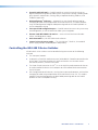
Controlling the MLS 608 D Series Switcher
All MLS 608 D series switchers can be controlled using one or more of the following
methods:
z The front panel controls.
z A computer, a TouchLink touchscreen panel, or MediaLink Controller connected to the
RS-232 port. These allow creation of a simple and intuitive user interface for the
MLS 608 D Switchers, and the entire room.
z The Extron Simple Instruction Set (SIS
™
): a set of simple keystroke commands that can
be used to control the devices via a computer or similar control device connected to
the RS-232 port
z DSP Configurator control software, running from a connected computer, and used for
managing all audio setup and operations of the MLS 608 D Series unit. This enables
complete setup and configuration of digital audio processing tools on the ProDSP
platform as well as microphone mixing.
MLS 608 D Series • Introduction 3

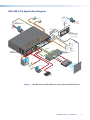
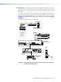
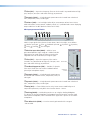
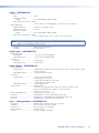
MLS 608 D SA Application Diagram
1
BUFFERED OUTPUT
MTP
+
AUDIO
+12 V OUT
PWR OUT=
12W
2
3
6
L
R
1
L R
2
L R
3
L R
5
L
R
7
L R
8
1
2 1 2
MIC/LINE
+ 48V
1
2
L R
L
R
Tx
+12V
Rx
8
4 (MTP)
CONFIGURABLE ANALOG INPUTS
AUDIO INPUTS
AUDIO OUTPUTS
RS-232
HOST
PWR OUT = 7.2W
DIGITAL OUTPUT
VIDEO + RS-232
ANALOG OUTPUT
DIGITAL INPUTS
5
7
L R
6
Tx
N/A
N/A
Rx
RS-232 INSERT
MLS 608 D MA
100-240V 50/60 Hz
3.2A MAX
1 2
70V - 40W
L R
1
BUFFERED OUTPUT
MTP
+
AUDIO
+12 V OUT
PWR OUT=
12W
2
3
6
L R
1
L
R
2
L R
3
L R
5
L R
7
L R
8
1
2 1
2
MIC/LINE
+ 48V
1
2
L
R L R
Tx
+12V
Rx
8
4 (MTP)
CONFIGURABLE ANALOG INPUTS
AUDIO INPUTS
AUDIO OUTPUTS
RS-232
HOST
PWR OUT = 7.2W
DIGITAL OUTPUT
VIDEO + RS-232
ANALOG OUTPUT
DIGITAL INPUTS
5
7
L
R
6
Tx
N/A
N/A
Rx
RS-232 INSERT
MLS 608 D SA
100-240V 50/60 Hz
3.2A MAX
1 2
4/8 OHM-20W x 2
Help Desk
Monitoring
and Control
Ethernet
TCP/IP
Network
DIGITAL OUTPUT
DIGITAL INPUT
POWER
12V
0.8A MAX
1 2
HDMI
RS-232
PASS THRU
Tx Rx
RGB
VID
Y/C
B-Y
Y
R-Y
ANALOG OUTPUTS
RS-232
Tx Rx
SPARE
MTP INPUT
1
MONO AUDIO
2
COMPUTER IN
AUDIO IN
CH 003
CH 003
PC
Microphones
Document
Camera
MTP + Audio
HDMI + Audio
HDMI + Audio
Projector
Control
Switcher
Control
Digital Video +
RS-232
Laptop
Extron
MLS 608 D SA
Extron
SI 3
Surface Mount
Speakers
Projector
Extron
MTP T 15HD A D
Transmitter
Screen
Control
Projector
Control
Extron
MLC 226 IP DV+
Enhanced MediaLink
Controller w/ IP Link
DISPLAY
1
2
3
4
5
6
VOLUME
IR
PC
AUX
VIDEO
DV
D
VCR
DOC
CAM
LAP
T
OP
A
U
TO
IMA
GE
ON
OFF
D
VD & VCR CONT
RO
L
PLAY
NEXT/FWD
PA
USE
STO
P
TUNER
Tx
PREV/REW
TITLE
MENU
ENTER
D
V
D
VCR
MLC 226 IP DV+
CONFIG
Blu-ray
Player
Extron
MTP/HDMI U R
Receiver
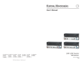
Figure 1. MLS 608 D SA and MTP/HDMI U R, with an Optional MLC 226 IP DV+
MLS 608 D Series • Introduction 4

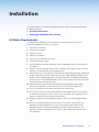
Installation
This section contains installation information for an MLS 608 D Series device and covers
the following subjects:
z UL/Safety Requirements
z Mounting the MLS 608 D Series Switcher
UL/Safety Requirements
The Underwriters Laboratories (UL) requirements listed below pertain to the safe
installation and operation of this AV Switcher.
1. Read these instructions.
2. Keep these instructions.
3. Heed all warnings.
4. Follow all instructions.
5. Do not use this apparatus near water.
6. Clean only with a dry cloth.
7. Do not block any ventilation openings. Install in accordance with the manufacturer’s
instructions.
8. Do not install near any heat sources such as radiators, heat registers, stoves, or other
apparatus (including amplifiers) that produce heat.
9. Do not defeat the safety purpose of the polarized or grounding type plug. A polarized
plug has two blades with one wider than the other. A grounding type plug has two
blades and a third grounding prong. The wide blade or the third prong are provided
for your safety. If the provided plug does not fit into your outlet, consult an electrician
for replacement of the obsolete outlet.
10. Protect the power cord from being walked on or pinched particularly at plugs,
convenience receptacles, and the point where they exit from the apparatus.
11. Only use attachments/accessories specified by the manufacturer.
12. Use only with the cart, stand, tripod, bracket, or table specied by the manufacturer,
or sold with the apparatus. When a cart is used, use caution when moving the cart/
apparatus combination to avoid injury from tip-over.
13. Unplug this apparatus during lightning storms or when unused for long periods of
time.
14. Refer all servicing to qualified service personnel. Servicing is required when the
apparatus has been damaged in any way, such as power-supply cord or plug is
damaged, liquid has been spilled or objects have fallen into the apparatus, the
apparatus has been exposed to rain or moisture, does not operate normally, or has
been dropped.
MLS 608 D Series • Installation 5

Mounting the MLS 608 D Series Switchers
If the device is to be rack mounted, it may be easier to do so before cabling it, depending
on the ease of access to the rear panel after mounting. Four rubber feet are included with
the unit. Install the feet only if the unit is to be mounted on a tabletop (see “Tabletop
placement” below).
Tabletop Placement
For tabletop placement, install the self-adhesive rubber feet/pads (provided) onto the four
corners of the bottom of the device.
UL Guidelines for Rack Mounted Devices
The following Underwriters Laboratories (UL) guidelines pertain to the safe installation of
the MLS 608 D Series switcher in a rack.
Elevated operating ambient temperature — If installed in a closed or multi-unit rack
assembly, the operating ambient temperature of the rack environment may be greater
than room ambient temperature. Therefore, install the device in an environment
compatible with the maximum ambient temperature (Tma = +122 °F, +50 °C) specified by
Extron.
Reduced air flow — Install the equipment in a rack so that the amount of air flow required
for safe operation of the equipment is not compromised.
Mechanical loading — Mount the equipment in the rack so that a hazardous condition is
not achieved due to uneven mechanical loading.
Circuit overloading — Connect the equipment to the supply circuit and consider the
effect that circuit overloading might have on overcurrent protection and supply wiring.
Appropriate consideration of equipment nameplate ratings should be used when
addressing this concern.
Reliable earthing (grounding) — Maintain reliable grounding of rack-mounted equipment.
Pay particular attention to supply connections other than direct connections to the branch
circuit (for example, use of power strips).
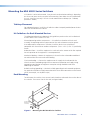
Rack Mounting
To rack mount the switcher, insert screws into the brackets and attach them to the sides of
the switcher. Then secure it to the the rack (see figure below).
2U Rack Mount
Bracket (use four
lower holes)
Figure 2. Mounting the MLS 608 D Series Switcher
MLS 608 D Series • Installation 6

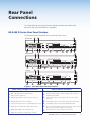
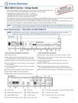
Rear Panel
Connections
This section describes the rear panel features and how to connect the cables to the
MLS 608 D and to the MTP/HDMI U R as applicable.
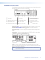
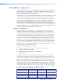
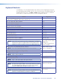
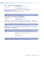
MLS 608 D Series Rear Panel Features
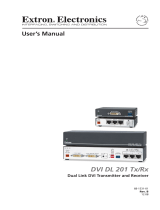
This illustration shows all possible features of the MLS 608 D Series.
1
BUFFERED OUTPUT
MTP
+
AUDIO
+12 V OUT
PWR OUT=
12W
2
3
6
LR
1
LR
2
LR
3
LR
5
LR
7
LR
8
12 12
MIC/LINE
+ 48V
1
2
LRLR
Tx
+12V
Rx
8
4 (MTP)
CONFIGURABLE ANALOG INPUTS
AUDIO INPUTS
AUDIO OUTPUTS
RS-232
HOST
PWR OUT = 7.2W
DIGITAL OUTPUT
VIDEO + RS-232
ANALOG OUTPUT
DIGITAL INPUTS
5
7
LR
6
Tx
N/A
N/A
Rx
RS-232 INSERT
MLS 608 D SA
100-240V 50/60 Hz
1.2A MAX
12
4/8 OHM - 20W x 2
MLS 608 D SA
14
3
1
4
8
5
13
12a
11
9
2
10
MLS 608 D MA
1
BUFFERED OUTPUT
MTP
+
AUDIO
+12 V OUT
PWR OUT=
12W
2
3
6
LR
1
LR
2
LR
3
LR
5
LR
7
LR
8
12 12
MIC/LINE
+ 48V
1
2
LRLR
Tx
+12V
Rx
8
4 (MTP)
CONFIGURABLE ANALOG INPUTS
AUDIO INPUTS
AUDIO OUTPUTS
RS-232
HOST
PWR OUT = 7.2W
DIGITAL INPUTS
5
7
LR
6
Tx
N/A
N/A
Rx
RS-232 INSERT
MLS 608 D MA
100-240V 50/60 Hz
1.2A MAX
12
ANALOG OUTPUT
DIGITAL OUTPUT
VIDEO + RS-232
12
1
BUFFERED OUTPUT
MTP
+
AUDIO
+12 V OUT
PWR OUT=
12W
2
3
6
LR
1
LR
2
LR
3
LR
5
LR
7
LR
8
12 12
MIC/LINE
+ 48V
1
2
LRLR
Tx
+12V
Rx
8
4 (MTP)
CONFIGURABLE ANALOG INPUTS
AUDIO INPUTS
AUDIO OUTPUTS
RS-232
HOST
PWR OUT = 7.2W
DIGITAL OUTPUT
VIDEO + RS-232
ANALOG OUTPUT
DIGITAL INPUTS
5
7
LR
6
Tx
N/A
N/A
Rx
RS-232 INSERT
MLS 608 D
100-240V 50/60 Hz
1.0A MAX
12
MLS 608 D
14
1
4
5
13
11
9
2
8
10
3
1
4
5
13
11
9
2
8
10
14
3
12b
6
7
70V - 40W
7
7
6
6
MTP
+
AUDIO
Figure 3. MLS 608 D Series Rear Panel Features
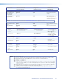
Power, analog, and digital connections Audio and RS-232 connections
a
AC power connector
i
Audio inputs, 5-pole captive screw connectors, (inputs 1-3, 5-8)
b
RGB, component/S-video/composite inputs,
VGA connectors, (inputs 1-3)
j
Mic/Line level audio inputs (1-2), 3-pole captive screw connectors
and phantom power LEDs
c
Buffered output, VGA connector (tied only to input 1)
k
Line level audio output, 5-pole captive screw connectors, (audio
outputs 1-2)
d
Universal MTP RJ-45 connector (input 4)
£
Power amplier output connector 4/8 ohm, 20 x 2 W (SA model)
e
2-pole power output connector, optional MTP power source
§
Power amplier output connector 70 V, 40 W (MA model)
f
Analog video and audio MTP output, RJ-45 connector
m
RS-232 control/conguration port and +12 V power out (for optional
MLC power source), 5-pole captive screw connector
g
Digital inputs, HDMI connectors (inputs 5-8)
n
RS-232 insertion port, 5-pole captive screw connector
h
Digital video and RS-232 outputs, RJ-45 connectors
MLS 608 D Series • Rear Panel Connections 7

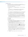
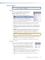
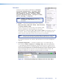
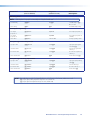
Power, Analog, and Digital Connections
a Power input — Connect the standard IEC power cord from a 100 to 240 VAC, 50 Hz
or 60 Hz power source into this connector. The front panel control and input selection
buttons light in sequence during power-up.
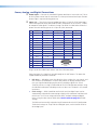
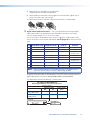
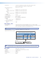
b Inputs 1-3 — These three universal analog input ports (15-pin HD [VGA] connectors)
can be congured to accept RGB (RGBHV, RGBs), component (bi- or tri-level), S-video,
or composite video signals. The default setting is for RGB. The table below shows the
pinouts for each format type on the 15-pin HD (VGA) connector.
Pin RGBHV RGBs Component S-video Composite
1 Red Red R-Y Chroma
2 Green Green Y Luma Video
3 Blue Blue B-Y
4 ID Bit ID Bit
5 N/C N/C
6 Red Return Red Return R-Y Return C Return
7 Green Return Green Return Y Return L Return Video Return
8 Blue Return Blue Return B-Y Return
9
10 Ground Ground
11 ID Bit ID Bit
12 ID Bit ID Bit
13 H Sync C Sync
14 V Sync
15 ID Bit ID Bit
Plug in up to three video input sources into these VGA connectors.
From these ports, the signals are passed through to the MPT output. The ports also
support RGB delay and EDID emulation.
z RGB delay — RGB delay mutes the video rst, then switches the sync signals, and
then switches the RGB video. This brief delay allows the display to adjust to the
new sync signal before displaying the picture, providing a glitch-free switch.
The delay can be set using SIS commands or the DSP Configurator software using
the Video I/O workspace. RGB delay can be set from 0 to 5 seconds in 0.5-second
increments.
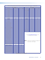
z EDID settings — EDIDs (resolution and refresh rates) for digital inputs can be
automatically assigned when connecting a display with a common resolution and
refresh rate. The user can assign a different EDID, for both analog and digital
inputs, using the data from an EDID table. See the table on page 23 for EDID
settings.
The EDID can be manually assigned using SIS commands or via DSP Congurator.
The default settings are 720p at 60 Hz for digital inputs, and 1024x768 at 60 Hz
for analog inputs.
HD15 Pin Locations
Female
51
15 11
610
MLS 608 D Series • Rear Panel Connections 8

c Buffered output — This buffered analog output is
tied only to input 1 and is a direct pass-through from
any video signal, such as composite, S-video, RGBs,
and YUV, that is present on input 1.
Connect a local output to this 15-pin HD (VGA)
connector for a buffered analog output from input 1.
The set signal type is output on the VGA connector,
however, for composite, S-video, RGBs, and YUV signals, break out cables are needed
when connecting a display.
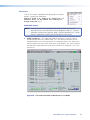
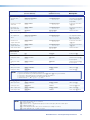
d Input 4 — This port is used to input universal MTP video signals with mono audio
support from an MTP transmitter. The input accepts composite, S-video, component
(bi-level and tri-level), and RGB (RGBHV and RGBS) video signals, but does not support
EDID emulation. When switching to this input, the incoming signal is passed to the
MTP output. The MTP HDMI U R receiver auto-detects the incoming video signal and
outputs it on the appropriate video connector.
The input supports level and peaking adjustment, setting the incoming signal to
appropriate levels.
Skew adjustment is available with this input, compensating for up to 64 nanoseconds
of skew. Adjustments are made using DSP Configurator software or SIS commands.
Settings are stored in the memory and recalled when the input is selected.
NOTE: • See the DSP Configurator Help File "Video Settings" section, or the
"SIS Programming and Control" section for method of skew adjustment.
• This port does not accept RS-232 commands from an MTP transmitter.
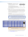
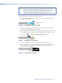
Connect to the transmitter by plugging a terminated CAT 5, 5e, or CAT 6 twisted pair
cable into these RJ-45 connectors. The T568A and T568B standard pinouts are shown
below. Use the same standard at both ends of the cable.
Pin T568A Wire Color T568B Wire Color Composite S-video Component RGBHV
1 White-green White-orange Reserved Chroma + R-Y + Red/V. Sync +
2 Green Orange Reserved Chroma - R-Y - Red/V. Sync -
3 White-orange White-green Mono Audio + Mono Audio + Mono Audio + Mono Audio +
4 Blue Blue Video + Luma + Y + Green +
5 White-blue White-blue Video - Luma - Y - Green -
6 Orange Green Mono Audio - Mono Audio - Mono Audio - Mono Audio -
7 White-brown White-brown Reserved Reserved B-Y + Blue/H. Sync +
8 Brown Brown Reserved Reserved B-Y - Blue/H. Sync -
CAUTION: Do not connect the MTP cable to any LAN port, telecommunications
network, or digital video output port.
Do not connect a LAN cable to any MTP or digital video output port.
The MLS-to-MTP input and output transmission distances for CAT 5, 5e, CAT 6, and
CAT 7 cable vary depending on the signal type, resolution and the quality of cable
used. See the table on page 10 for distances.
12345678
RJ-45
Connector
Insert Twisted
Pair Wires
Pins:
1
BUFFERED OUTPUT
CONFIGURABLE ANALOG INPUTS
MLS 608 D Series • Rear Panel Connections 9

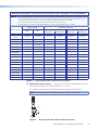
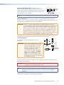
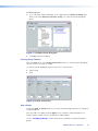
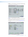
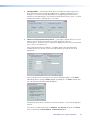
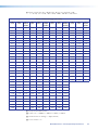
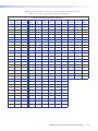
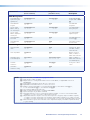
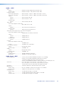
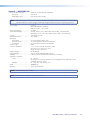
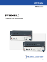
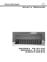
MLS 608 D Analog Signal Transmission Distance Table for Inputs and Outputs, in Feet and (Meters)
NOTE: • The maximum transmission distances are determined by the frequency and resolution of the video signal being
routed. The table below species the recommended maximum distances when using Extron Enhanced Skew
Free AV UTP cable or UTP CAT 5, 5e, or CAT 6 cable, terminated with RJ-45 connectors.
• The minimum TP cable length should be 25 feet from the MTP Tx to input 4.
• It is possible to exceed the recommended distances; however, image quality may be reduced.
Video Format
MLS Pre-Peak Maximum Distance
Off On
High Quality Variable Quality
MLS Input MLS Output MLS Input MLS Output
Component,
S-video
<300 (90) >350 (105) 700 (215) 700 (215) 700 (215) 800 (245)
Composite
<300 (90)
>350 (105) 700 (215) 700 (215) 750 (230) 750 (230)
640x480
<300 (90)
>350 (105) 550 (170) 600 (185) 600 (185) 650 (200)
800x600
<300 (90)
>350 (105)
500 (150) 500 (150) 600 (185) 600 (185)
1024x768*
<300 (90)
>350 (105)
450 (135) 450 (135) 550 (170) 550 (170)
1280x960*
<300 (90)
<350 (105)
350 (105) 350 (105) 450 (135) 450 (135)
1280x1024*
<250 (75) >300 (90) 350 (105) 350 (105) 450 (135) 450 (135)
1360x765
<250 (75) >300 (90) 350 (105) 350 (105) 500 (150) 500 (150)
1365x768
<250 (75) >300 (90) 350 (105) 350 (105) 450 (135) 450 (135)
1366x768
<250 (75) >300 (90) 350 (105) 350 (105) 450 (135) 450 (135)
1440x900
<250 (75) >300 (90) 350 (105) 300 (90) 400 (120) 400 (120)
1400x1050
<250 (75) >300 (90) 350 (105) 300 (90) 400 (120) 400 (120)
1600x1200
<250 (75) >300 (90) 300 (90) 300 (90) 450 (135) 450 (135)
1920x1200
<200 (60) >250 (75) 300 (90) 250 (75) 400 (120) 400 (120)
HDTV 720p
<250 (75) >300 (90) 400 (120) 400 (120) 500 (150) 500 (150)
HDTV 1080i
<200 (60) >250 (75) 300 (90) 250 (75) 400 (120) 400 (120)
HDTV 1080p
<200 (60) >250 (75) 300 (90) 250 (75) 400 (120) 400 (120)
Figure 4. Transmission Distance Table for Analog Signals
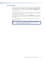
e Optional MTP power output — This port is for use with an MTP/HDMI U R receiver,
and is rated at 12 VDC with a current draw of 1 A, 12 watts.
This supplies sufficient power via the MLS device to fully power the MTP unit.
NOTE: When the power save mode is set to on, this port also turns off.
Captive Screw
Connector
Tie Wrap
3
5
Figure 5. Wiring the MLS 608 D Power Output Connector
MLS 608 D Series • Rear Panel Connections 10

f Analog MTP output (audio and video) — This output transmits signals from an
active analog input over CAT 5 cable to the MTP/HDMI U R receiver. It is also capable
of transmitting line level mono audio over the same cable as audio output 3.
The output also supports pre-peaking adjustment for optimizing video signals for long
cable runs.
Skew adjustment is available on this ouput, compensating for up to 64 nanoseconds
of skew. Adjustments are made using DSP Configurator software or SIS commands.
Settings are stored in the memory and recalled when the input is selected.
Connect the MTP HDMI U R twisted pair receiver (supplied) for analog audio and
video output.
NOTES: • See the table on page 9 for pinout details.
• See the table on page 10 for output transmission distances.
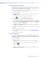
g Digital Inputs 5-8 — These four HDMI inputs are HDMI 1.3 compatible and have the
following features:
z HDCP authentication – The MLS 608 D gives a status feedback if it detects any
of the following are valid:
z If a source is HDCP compliant
z If a source has active video
z If a display is HDCP compliant (only if connected input is encrypted)
If the source is HDCP compliant but the display is not, the MLS displays a green
screen at the output.
See "HDCP Compliance" within the "DSP Configurator" section, for the detailed
method of HDCP detection and operation.
z Digital input equalization — Each digital input has automatic equalization to
compensate for distance from the source to the input. This gives 1080p, 8-bit
color, with a maximum distance of 50 feet using Extron Pro Series HDMI cable.
NOTE: The transmission distance varies greatly depending on the signal
resolution, and on the type of cable, graphics card and display used in
the system.
z Audio de-embedding — Each of the HDMI inputs de-embed 2-channel PCM
audio signals at 48 Hz only. Other audio signals are not de-embedded: the signal
will be muted at the DSP processor and audio will not be heard.
The audio to be de-embeded is user selectable from either the existing embedded
digital audio or a local analog input. The default is digital audio.
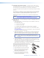
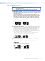
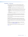
Connect up to four digital HDMI and DVD-D inputs to
the HDMI connectors
g
. Connect DVI-D sources using an
adapter cable and secure the connectors to the
MLS 608 D using the LockIt
™
bracket as follows:
1. Plug the HDMI cable into the panel connection.
2. Loosen the HDMI connection mounting screw
from the panel enough to allow the LockIt
lacing bracket to be placed over it.
3. Place the LockIt lacing bracket on the screw
and against the HDMI connector, then tighten
the screw to secure the bracket.
3
4
3
1
2
MLS 608 D Series • Rear Panel Connections 11

4. Loosely place the included tie wrap around the
HDMI connector and LockIt lacing bracket.
5. While holding the connector securely against the lacing bracket, tighten the tie
wrap, then remove any excess length.
The LockIt bracket can be mounted in different orientations, as shown below.
Top Mounted
3
Side Mounted
Stacked
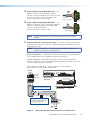
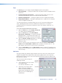
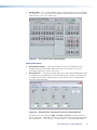
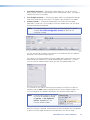
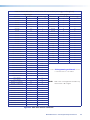
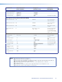
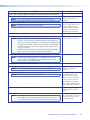
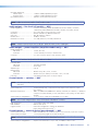
h Digital video and RS-232 outputs — These two RJ-45 connectors output digital
video signals and RS-232 commands to the MTP/HDMI U R receiver over Extron
STP 201 (recommended), CAT 5, 5e or CAT 6 cable.
The RS-232 signal is bi-directional and its source is tied to the 5-pole, captive screw,
RS-232 Insert port. See the pinout table below. See
n
(page 16) for the transmission
path.
Pin T568A Wire Color T568B Wire Color RJ-45 #1 RJ-45 #2
1 White-green White -orange Data 0 + CEC
2 Green Orange Data 0 - HPD
3 White-orange White-green ID Clock + Serial +
(RS-232 Insert)
4 Blue Blue Data 1 + DDC Clock
5 White-blue White-blue Data 1 - N/A
6 Orange Green ID Clock - Serial +
(RS-232 Insert)
7 White-brown White-brown Data 2 + DDC Data
8 Brown Brown Data 2 - Ground
NOTE: Terminate both ends of the same cable identically, in accordance with
either the TIA/EIA T568A or TIA/EIA T568B wiring standard.
Plug terminated cable from the MTP HDMI U R in to these two RJ-45 connectors for
digital video and RS-232 output. Using STP201 cable is recommended.
The digital signal transmission distance is shown below.
MLS 608 D
AUX
VID
PC
DOC
CAM
Blu-ray
VOLUME
SOURCE SELECTION
CONFIG
R
MIC VOLUME
AV Switcher
LAPTOP
12345678
MLS 608 D
MTP/HDMI U R
MTP/HDMI U R
RGB
PEAKINGLEVELDIGITAL SIGNAL
ANALOG
SIGNAL
AUDIO
RS-232
VID
Y/C
YUV
RGB
CAT 5/5e/6 Cable
Extron STP201
UTP STP Cable
200' (60 m) 200' (60 m) 200' (60 m)
100' (30 m) 125' (38 m) 150' (46 m)
Resolutions
MLS 608 D to MTP/HDMI U R
Digital Signal Maximum Transmission Distances
1024x768,
720p, 1080i @ 60 Hz
1600x1200, 1920x1200,
1080p @ 60 Hz
8-bit Color Depth
MLS 608 D Series • Rear Panel Connections 12

NOTES: • Transmission distance varies greatly depending on the signal resolution,
and the type of cable, graphics card and display used in the system.
• Shielded twisted pair cable provides added protection from outside
interference and increases overall signal transmission distance.
Extron recommends using shielded twisted pair for optimal performance.
When using STP cable, terminate the cable as follows:
1. For each cable, peel back the cable shielding from the end of the cable 7/8 inch
[2.2 cm]) and fold it back.
Peel back shield and
fold back.
Figure 6. Peeling Back the Cable Shielding
2. Cut away and discard the clear cellophane inner wrapper from the end of the
cable back to the folded-over cable shielding.
3. Peel the backing off the self-adhesive shielded aluminum tape and wrap it around
the folded-over cable shielding, slightly overlapping the beginning of the tape.
Aluminum Tape
Wrap tape around folded foil shielding with a slight overlap.
Cut and save the excess tape for other connectors.
Figure 7. Wrapping the Shielded Tape
4. Cut the unused portion of the shielded tape and retain for further uses.
5. Feed each individual wire into the appropriate slot of the RJ-45 connector and
crimp the cable in the normal manner, folding the tangs at the end of the
connector over the shielded tape.
Crimped Connector
Figure 8. Crimped RJ-45 Connector
MLS 608 D Series • Rear Panel Connections 13

Audio and RS-232 Connections
NOTES: When wiring the connectors for the ports listed below:
• DO NOT tin the wires.
• Bare the wires to a maximum length of 3/16 inch (5 mm) only.
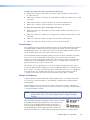
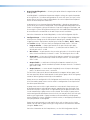
i Audio inputs 1-3 and 5-8 — These 5-pole captive screw connectors support analog,
balanced or unbalanced, stereo audio as three line level inputs (1-3) and four line level
analog stereo inputs (5-8).
Audio from the HDMI inputs 5-8 can be de-embeded from the HDMI source. This
allows the user to choose to select audio either from the HDMI inputs or the analog
audio from these four captive screw inputs. Once an audio source is selected, the
unselected source is disabled. The default selection is audio from the HDMI inputs.
Connect audio sources to these 5-pole, captive screw connectors. Wire the connector
for line level analog stereo as shown below.
LR
Unbalanced Input
Balanced Input
Ring
Sleeve (s)
Tip
Sleeve
Tip
Sleeve
Tip
Tip
Ring
j MIC/Line level audio inputs 1-2 — These two 3-pole, captive screw connectors are
microphone or line level inputs for balanced or unbalanced mono audio. They also
have +48 V phantom power support and two rear panel LEDs that indicate when
phantom power is activated. The phantom power can be activated through
DSP Configurator. See the DSP Configurator Help File "Mic/Line Input Gain" section,
for the method of enabling and disabling phantom power.
Connect microphone or line level audio inputs to these 3-pole, captive screw
connectors. Wire the connector for mono audio as shown below.
Balanced Mic Input
Unbalanced Mic Input
Tip
Ring
Sleeve
Tip
Sleeve
k Line level audio outputs 1-2 — Connect audio output devices to these 5-pole,
captive screw connectors.
Wire the connectors for line level analog stereo output as shown below.
Unbalanced Output Balanced Output
Tip
NO Ground Here
Slee
ve(s)
Tip
NO Ground Here
LR
AUDIO
Tip
Ring
Sleeve(s)
Tip
Ring
LR
AUDIO
CAUTION
For unbalanced audio, connect the sleeve(s) to the ground contact.
DO NOT connect the sleeve(s) to the negative (-) contacts
.
MLS 608 D Series • Rear Panel Connections 14
Page is loading ...
Page is loading ...
Page is loading ...
Page is loading ...
Page is loading ...
Page is loading ...
Page is loading ...
Page is loading ...
Page is loading ...
Page is loading ...
Page is loading ...
Page is loading ...
Page is loading ...
Page is loading ...
Page is loading ...
Page is loading ...
Page is loading ...
Page is loading ...
Page is loading ...
Page is loading ...
Page is loading ...
Page is loading ...
Page is loading ...
Page is loading ...
Page is loading ...
Page is loading ...
Page is loading ...
Page is loading ...
Page is loading ...
Page is loading ...
Page is loading ...
Page is loading ...
Page is loading ...
Page is loading ...
Page is loading ...
Page is loading ...
Page is loading ...
Page is loading ...
Page is loading ...
Page is loading ...
Page is loading ...
Page is loading ...
Page is loading ...
Page is loading ...
Page is loading ...
Page is loading ...
Page is loading ...
Page is loading ...
Page is loading ...
Page is loading ...
Page is loading ...
Page is loading ...
Page is loading ...
Page is loading ...
Page is loading ...
Page is loading ...
Page is loading ...
Page is loading ...
Page is loading ...
Page is loading ...
Page is loading ...
Page is loading ...
Page is loading ...
Page is loading ...
Page is loading ...
Page is loading ...
Page is loading ...
Page is loading ...
Page is loading ...
Page is loading ...
Page is loading ...
Page is loading ...
Page is loading ...
Page is loading ...
Page is loading ...
Page is loading ...
Page is loading ...
Page is loading ...
Page is loading ...
Page is loading ...
-
 1
1
-
 2
2
-
 3
3
-
 4
4
-
 5
5
-
 6
6
-
 7
7
-
 8
8
-
 9
9
-
 10
10
-
 11
11
-
 12
12
-
 13
13
-
 14
14
-
 15
15
-
 16
16
-
 17
17
-
 18
18
-
 19
19
-
 20
20
-
 21
21
-
 22
22
-
 23
23
-
 24
24
-
 25
25
-
 26
26
-
 27
27
-
 28
28
-
 29
29
-
 30
30
-
 31
31
-
 32
32
-
 33
33
-
 34
34
-
 35
35
-
 36
36
-
 37
37
-
 38
38
-
 39
39
-
 40
40
-
 41
41
-
 42
42
-
 43
43
-
 44
44
-
 45
45
-
 46
46
-
 47
47
-
 48
48
-
 49
49
-
 50
50
-
 51
51
-
 52
52
-
 53
53
-
 54
54
-
 55
55
-
 56
56
-
 57
57
-
 58
58
-
 59
59
-
 60
60
-
 61
61
-
 62
62
-
 63
63
-
 64
64
-
 65
65
-
 66
66
-
 67
67
-
 68
68
-
 69
69
-
 70
70
-
 71
71
-
 72
72
-
 73
73
-
 74
74
-
 75
75
-
 76
76
-
 77
77
-
 78
78
-
 79
79
-
 80
80
-
 81
81
-
 82
82
-
 83
83
-
 84
84
-
 85
85
-
 86
86
-
 87
87
-
 88
88
-
 89
89
-
 90
90
-
 91
91
-
 92
92
-
 93
93
-
 94
94
-
 95
95
-
 96
96
-
 97
97
-
 98
98
-
 99
99
-
 100
100


Extron MLS 608 D User manual
- Category
- Supplementary music equipment
- Type
- User manual
Ask a question and I''ll find the answer in the document
Finding information in a document is now easier with AI
Related papers
-
Extron DXP HDMI Series Owner's manual
-
 Extron electronics MLS 608 D MA User manual
-
 Extron electronics SW HDMI LC User manual
-
 Extron electronics SW HDMI Series User manual
-
Extron MTP R AV & MTP R AV RCA User manual
-
-
-
-
Extron electronics DVI-RGB 200 User manual
-
Extron MLC 226 IP User manual


Other documents
-
CYP RE-EDID Owner's manual
-
Kramer Electronics TP-125 Datasheet
-
 Extron electronics RSB129 User manual
-
Extron electronic MLC 52 User manual
-
-
Key Digital FATBOY KD-MSW4X2 User manual
-
Altinex MX2436RM User manual
-
 Extron electronics DVI DL 201 Tx User manual
-
 Extron electronics 8 PLUS User manual
-
Extron electronics Universal Mini Twisted Pair Receivers MTP U R Series User manual


