Page is loading ...

IMPORTANT:
Go to www.extron.com for the complete
user guide, installation instructions, and
specifications before connecting the
product to the power source.
MTP SW6 • Setup Guide
This card provides quick start instructions for an experienced installer to set up and operate the MTP SW6 switcher.
Installation
Step 1 — Mounting
5
Pin
1
2
3
6
7
8
4
Wire color
White-green
Green
White-orange
White-blue
Orange
White-brown
Brown
Wire color
T568A T568B
White-orange
Orange
White-green
White-blue
Green
White-brown
Brown
Blue Blue
Insert
TP Wires
Pins:
1 2345678
123456
INPUT
PRE-PEAK
ON
OFF
OUTPUT
NOTE: If you are using Enhanced Skew-Free™ A/V cable,
use the TIA/EIA T568A standard only.
Turn off or disconnect all equipment power sources and mount the MTP switcher as required.
Step 2 — TP Inputs from the Transmitters
Terminate up to six TP cables as shown at right. Connect them between MTP transmitters
and the Input connectors (both ends need to match).
Step 3 — RS-232 Insert Connector
For bidirectional RS-232 data that is routed from a common source to the TP output
regardless of the selected input, plug a serial device into the RS-232 Insert connector.
NOTES:
• For the RS-232 insert to be available on the TP output, it must be enabled by issuing
the
E
1*1Lrpt
}
SIS command to the switcher (see the MTP SW6 User Manual).
• When the RS-232 insert is enabled, any content on the audio/RS-232 wire pair for the
TP input tied to the output is disabled.
Step 4 — TP Output to the Receiver
Terminate a TP cable as shown for step 2. Connect it between the Output connector and receiver
that is compatible with the transmitters.
NOTE: The input and all outputs should all be terminated using the same standard on both
ends of the cables.
Step 5 — Connect a Local Audio Device
Connect an audio device to the Mono Audio connector. Wire the connectors as shown at right.
ATTENTION: For unbalanced audio output, connect the sleeves to the ground contact. DO
NOT connect the sleeves to the negative (-) contacts.
Step 6 — Remote Connector (Optional)
Connect an RS-232 device OR a contact closure device, such as a KP 6 Keypad Remote Control.
NOTES:
• For RS-232 control, use a cable with ONLY pins 2, 3, and 5 connected.
• For contact closure control, use a cable with pins 2 and 3 NOT connected.
RS-232 communications protocols:
• 9600 baud • 8 data bits
• 1 stop bit, no parity • no ow control
For contact closure control, short the pin for the desired input to pin 5 to select that device. To
force an input to be always selected, leave the short in place.
NOTES:
• For contact closure control, auto switch mode must be off.
• Contact closure control overrides front panel input selections.
Receive (Rx)
Transmit (Tx)
Ground ( )
Bidirectional
RS-232 Device
Ground ( )
Receive (Rx)
Transmit (Tx)
RxTx
SPARE
Do not tin the wires!
REMOTE
1
MONO AUDIO
2
1
MONO AUDIO
2
Unbalanced Output
Balanced Output
Do not tin the wires!
Mono output 1-
Sleeve(s)
Mono output 1+
Mono output 2+
Mono output 2-
Sleeve(s)
Mono output 1
Mono output 2
NO GROUND.
NO GROUND.
Pin
RS-232
Contact
Closure
Function
1 — In #1 Input #1
2 TX — Transmit data
3 RX — Receive data
4 — In #2 Input #2
5 Gnd Gnd Ground
6 — In #3 Input #3
7 — In #4 Input #4
8 — In #5 Input #5
9 — In #6 Input #6

68-1462-50 Rev. C
01 13
Extron Headquarters
+800.633.9876 Inside USA/Canada Only
Extron USA - West Extron USA - East
+1.714.491.1500 +1.919.850.1000
+1.714.491.1517 FAX +1.919.850.1001 FAX
Extron Europe
+800.3987.6673
Inside Europe Only
+31.33.453.4040
+31.33.453.4050 FAX
Extron Asia
+800.7339.8766
Inside Asia Only
+65.6383.4400
+65.6383.4664 FAX
Extron Japan
+81.3.3511.7655
+81.3.3511.7656 FAX
Extron China
+4000.EXTRON
+4000.398766
Inside China Only
+86.21.3760.1568
+86.21.3760.1566
FAX
Extron
Middle East
+971.4.2991800
+971.4.2991880 FAX
Extron Korea
+82.2.3444.1571
+82.2.3444.1575 FAX
Extron India
1800.3070.3777
Inside India Only
+91-80-3055.3777
+91 80 3055 3737
FAX
© 2013 Extron Electronics All rights reserved. www.extron.com
MTP SW6 • Setup Guide (continued)
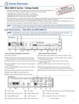
Step 7 — Power
Power Supply
Output Cord
SECTION A–A
Ridges
Smooth
AA
Tie
Wrap
POWER
12V
xA MAX
Rear
Panel
Ridges
Earth
Ground
3/16"
(5 mm)
Max.
Wire the 2-pole captive screw connector for the included external 12 VDC power supply (see
image a on the right). Plug it into the switcher.
Grounding guidelines
An Extron MTP SW6 can be adversely affected by electrostatic discharge (ESD) if it is not grounded
correctly.
To prevent malfunctions or product damage, an experienced installer can correctly ground an
Extron MTP SW6 in either of two ways:
• Ground the power input port — Insert one end of the grounding wire to the negative or ground
pin on the power input connector (see image a on the right). Tie the other end of the wire to an
earth ground.
• Ground the chassis — Use a connector hex nut (see image b the right). Tie the other end of
the wire to an earth ground.
If you have any questions about how to ground a product in a specic application, contact an Extron technical
support specialist.
Step 8 — Pre-Peak, Peaking, and Level
• Pre-Peak switch — View the image and set the Pre-Peaking switch for the best image quality to correct for
long cable runs of the entire system (including all daisy-chained receivers).
• Peaking control — View the image and adjust the Peaking control for the best image sharpness. Minimum
RGB
PEAKING
LEVEL
setting (full counterclockwise) is zero peaking.
• Level control — View the image and adjust the Level control for the best brightness level.
NOTES:
• The simplest and surest way to set the input level and peaking is to use an optional MTP signal generator and the Execute auto-
calibration SIS command (see the MTP SW6 User’s Manual for details).
• The switcher must be running rmware version 1.02 or newer. Older rmware versions appear to respond correctly, but do not adjust
the level and peaking values correctly.
Step 9 — Skew Compensation
Pair skew can be measured with test equipment or by viewing a crosshatch test pattern. Adjust the equalization for the
DELAY
RED
GREEN
BLUE
SELECT
selected input as follows:
1. Zero the skew delay for red, green, and blue by using a Tweeker or mall screwdriver to press and hold the Select
button for 3 seconds. When the Red, Green, and Blue LEDs all go out, release the Select button.
2. Use UTP cable test equipment or examine the displayed image to determine which video signal — red, green, or blue
is shifted furthest to the right.
3. Select the furthest left video signal by using a Tweeker to press and release the Select button until the LED for the left-shifted color — Red,
Green, or Blue — lights.
4. Slowly rotate the Adjust control clockwise until the selected color is properly converged.
5. If the remaining colors are left shifted, repeat steps 3 and 4.
6. Repeat steps 1 through 5 for each input.
Operation
Select an input — Press and release the desired input button.
Toggle auto switch mode on and off —
1. Press and hold the Mode (Input 1) button.
2. Press and release the Auto or Normal button.
3. Release the Mode button.
a
b
/