Page is loading ...

OPERAT
OR’S MANUAL
650295
RELEASED:
6–27–95
(REV
. A) IPP
INCLUDING: OPERATION, INSTALLATION & MAINTENANCE
PUMP
SYSTEM
ALSO INCLUDE MANUALS: 650691-X PUMP, 651616-X TWO POST LIFT/RAM & 65940 AIR MANIFOLD
23:1
RA
TIO
6” AIR MOTOR
6” STROKE
650295
READ THIS MANUAL CAREFULL
Y BEFORE INST
ALLING,
OPERA
TING OR SER
VICING THIS EQUIPMENT
.
CARBON STEEL
THE
ARO CORPORA
TION
D
ONE ARO CENTER
D
BR
Y
AN, OHIO 43506–0151
E1995
THE ARO CORPORA
TION
D PRINTED IN U.S.A.
&
(419) 636–4242
D
F
AX (419) 636–21
15
1
2
3
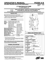
Control Panel
(See Page 2)
Material
Outlet
FIGURE 1
4
F033
SERVICE KITS
• Use only genuine ARO replacement parts to assure compatible
pressure rating and longest service life.
• 61355 for repair of Air Motor Section.
• 637071-XXX for repair of Lower Pump 66243-X.
GENERAL
DESCRIPTION
WARNING DO NOT EXCEED MAXIMUM OPERATING
PRESSURE OF 4,215 P.S.I. (294 BAR) AT 150 P.S.I. (10.4 BAR)
AIR INLET PRESSURE.
WARNING REFER TO GENERAL INFORMATION SHEET
FOR ADDITIONAL SAFETY PRECAUTIONS AND IMPORĆ
TANT INFORMATION.
By delivering a smooth, continuous bead of the proper size, an ARO
system helps the operator maintain both his production rate and proĆ
duce quality standards. Maintained quality standards assures that the
material benefits are realized. To further maximize operator production
time, the ARO System has a built-in lift/ram feature for quick and easy
drum changeover.
ARO Systems are totally enclosed, sealing the material in the system
from air and moisture, preventing premature cure-out of the material.
This allows for either continuous or intermittent use of the system and
reduces the need for daily system clean-up.
Built-in lift capability allows for quick drum changeover and easy lifting
of pump assembly from container.
The 23:1 ratio is an expression of the relationship between the effecĆ
tive air motor area and the effective lower pump area. When 150 PSI
(10 bar) of air pressure is supplied to the air motor, the lower pump area
will develop a maximum of 4,215 PSI (294 bar) of fluid pressure (at no
flow) as the fluid control is opened, the flow rate will increase as the air
motor cycle rate increases to keep up with the demand.
MAJOR COMPONENTS LIST
Item Description Qty Part No. Item Description Qty Part No.
1 Two Post Ram 1 67081 3 Basic Pump Assembly 1 650891-G43
2 Follower Plate 1 66516-1 4 Air Manifold 1 65940

PAGE2OF4 650295
INSTALLATION
The 650295 Chop-Check Dispensing System comes completely asĆ
sembled. Remove unit from crate and place on a level surface. Install
material hose and dispensing device as required.
When the following instructions are observed, heavy paste materials
can be pumped directly from their original 5 or 55 gallon drum without
air inclusion, or excessive waste. The follower plate creates an air tight
seal as well as clean-wiping action in its progressive downward moveĆ
ment into the drum.
OPERATING INSTRUCTIONS
OPERATING INSTRUCTIONS / INITIAL SETUP PROCEDURE
WARNING STAND CLEAR. When raising or lowering the
lift. Read the warning on page 2 of 651616-X Two Post Lift/Ram
Operator's Manual.
FOLLOWER PLATE
AIR SUPPLY VALVE
AIR CONTROLS
FIGURE 2
2
AIR
INLET
CONTROL
LEVER
GAUGE
OFF
ON
PRESSURE
REGULATOR
F034
TO RAISE LIFT, (THE FIRST TIME):
1. Take note of the pump/drum clearance above. Be certain the lift is
clear of any objects above. Also refer to OPERATING AND SAFEĆ
TY PRECAUTIONS found on page 2 of 651616-X Two Post Lift/
Ram Operator's Manual.
2. Connect the air supply (160 PSI MAX) to the air inlet. Adjust (Turn Lift/
Ram Pressure Regulator Knob Clockwise) air pressure on lift/ram presĆ
sure regulator to 20 P.S.I. (1.2 Bar)
3. Shift the control valve lever to the ``UP'' position.
4. Raise the Lift/Ram high enough to clear the height of the drum.
Stop the lift upward travel by moving the control valve lever to the
(center) ``NEUTRAL'' position.
REFER TO PAGE 3:
1. Once Lift/Ram assembly and pump are in the ``UP" position, place
and center an opened 5 or 55 gallon drum of material on the lift/ram
base.
2. Lubricate lower follower wiper plate seal with any type grease. (siliĆ
cone, vaseline, gear, etc.) This ensures a smooth fit into the drum
as well as prevents curing type compounds from bonding to seal.
3. Check vent plug on follower plate to be sure it easily threads in and
out. It is recommended to lubricate the threads of the plug to help
prevent possible set up of compound at this point. See 651616-X
Operator's Manual.
TO LOWER LIFT:
WARNING
PINCH HAZARD. Follower can descend quickly
causing injury. Keep hands clear when aligning with containĆ
er. Read the warning on page 2 of 651616-X Two Post Lift/Ram
Operator's Manual.
NOTE: Be certain the Follower Plate vent plug has been removed
so that the air trapped between the follower and the material is allowed
to escape from this vent. Captured air between the follower plate and
drum will escape.
NOTE: The Lift/Ram may hesitate momentarily before starting downĆ
ward, the air pressure inside the post air chamber must decrease beĆ
fore it will begin to descend.
1. Shift the control valve lever to the ``DOWN'' position and proceed
to lower the pump.
2. Replace the vent plug once the material begins to ooze from the
vent opening.
3. The unit is now ready for operation. Adjust (Turn pump regulator
Clockwise) air pressure on pump Filter/Regulator until pump beĆ
gins to cycle.
4. Trigger gun to prime pump with material.
TO RAISE LIFT, (NORMAL OPERATION):
1. Adjust the Follower Plate Air Valve pressure up to approximately 8
psig. DO NOT OVERPRESSURIZE THE DRUM to avoid damĆ
age.
NOTE: Air from this valve will only pass when the Control Lever is
in the ``UP'' position.
2. Shift the control valve lever to the ``UP'' position.
3. Raise the Lift/Ram high enough to clear the height of the drum.
Stop the lift upward travel by moving the control valve lever to the
(center) ``NEUTRAL'' position.
TO CHANGE DRUM:
NOTE: The Control Lever should be in the ``NEUTRAL'' position.
1. Unsrew thumb screw and remove old drum.
2. Place and center a new drum into position. Remove cover. Tighten
thumb screw.

FIGURE 3
650295 PARTS LIST
Air Inlet
24"
(609 MM)
61"
(1549 MM)
BASIC PUMP
650691-G43
Muffler
91790
Nipple 90818Z
Elbow Y43-316-C
39.5"
(1003 MM)
FOLLOWER PLATE
AIR SUPPLY VALVE
RETRACTED
Air Manifold Assembly
65940
Two Post Lift/Ram
651616-2
consists of:
67081 Ram Assembly
66516-1 Follower Assembly
Air Controls
(See Page 2)
Z Apply Anaerobic Pipe
Thread Sealant to Male
Threads
FOLLOWER
PLATE VENT
PLUG 66045
(Air to Pump)
F039
PAGE3OF4
650295

PAGE4OF4 650295
PN 97999-631
/