Page is loading ...

Instructions - Parts
SmartWare
™
Shot
Dispense Kit
Accurate metered dispensing kit for one component materials. Kits are compatible with
Check-Mate
®
pumps and Dura-Flo
™
pumps; both alone and as part of a supply system. For
professional use only.
Not approved for use in European explosive atmosphere locations.
Kit 262370 for D200 and D60
For D200 3 inch dual post ram with NXT
®
2200 and larger air motors
For D60 3 inch dual post ram with NXT2200 and larger air motors
Kit 262371 for D200
For D200 3 inch dual post ram with NXT1800 and smaller air motors
Kit 262372 for D200S
For D200S 6 inch dual post ram with NXT2200 and larger air motors
Kit 262373 for S20
For S20 3 inch single post ram NXT2200 and larger air motors
Kit 262374 for S20
For S20 3 inch single post ram with NXT1800 and smaller air motors
Kit 262375 for pumps
For wall mount or floor stand pump with NXT2200 and larger air
motors
Important Safety Instructions
Read all warnings and instructions in this manual.
Save these instructions.
Kit 262370 Shown
3A0294G
EN

2 3A0294G
Contents
Related Manuals . . . . . . . . . . . . . . . . . . . . . . . . . . . 3
Warnings . . . . . . . . . . . . . . . . . . . . . . . . . . . . . . . . . 4
System Description . . . . . . . . . . . . . . . . . . . . . . . . . 6
Typical Applications . . . . . . . . . . . . . . . . . . . . . . . 6
Compatibility . . . . . . . . . . . . . . . . . . . . . . . . . . . . 6
Critical System Parameters . . . . . . . . . . . . . . . . . 6
Theory of Operation . . . . . . . . . . . . . . . . . . . . . . . . 7
Component Identification . . . . . . . . . . . . . . . . . . . . 8
User Interface . . . . . . . . . . . . . . . . . . . . . . . . . . 10
Grounding . . . . . . . . . . . . . . . . . . . . . . . . . . . . . . . 15
Installation . . . . . . . . . . . . . . . . . . . . . . . . . . . . . . . 16
Location . . . . . . . . . . . . . . . . . . . . . . . . . . . . . . 16
Install Kits 262370 and 262372 . . . . . . . . . . . . . 16
Install Kit 262371 . . . . . . . . . . . . . . . . . . . . . . . 24
Install Kit 262373 . . . . . . . . . . . . . . . . . . . . . . . 30
Install Kit 262374 . . . . . . . . . . . . . . . . . . . . . . . 37
Install Kit 262375 . . . . . . . . . . . . . . . . . . . . . . . 43
Setup . . . . . . . . . . . . . . . . . . . . . . . . . . . . . . . . . . . . 50
Enter Password . . . . . . . . . . . . . . . . . . . . . . . . . 50
Setup Pump . . . . . . . . . . . . . . . . . . . . . . . . . . . 50
Pressure Relief Procedure . . . . . . . . . . . . . . . . . . 51
Prime/Purge . . . . . . . . . . . . . . . . . . . . . . . . . . . . . . 52
Set System Parameters . . . . . . . . . . . . . . . . . . . . . 53
Set Units and Specific Gravity . . . . . . . . . . . . . . 53
Define Shot Size . . . . . . . . . . . . . . . . . . . . . . . . 54
Define Shot Sequence . . . . . . . . . . . . . . . . . . . 55
Set Password . . . . . . . . . . . . . . . . . . . . . . . . . . 56
Select Pump . . . . . . . . . . . . . . . . . . . . . . . . . . . 57
Enable/Disable Pump Functions . . . . . . . . . . . . 57
Enable/Disable Errors . . . . . . . . . . . . . . . . . . . . 58
Set Low/Empty Drum Error . . . . . . . . . . . . . . . . 58
Set Pump Runaway Error . . . . . . . . . . . . . . . . . 59
Set Maintenance Parameters . . . . . . . . . . . . . . 59
Calibrate . . . . . . . . . . . . . . . . . . . . . . . . . . . . . . 60
Set Shot Accuracy Errors . . . . . . . . . . . . . . . . . 61
Operation . . . . . . . . . . . . . . . . . . . . . . . . . . . . . . . . 62
Startup . . . . . . . . . . . . . . . . . . . . . . . . . . . . . . . 62
Change Operation Mode . . . . . . . . . . . . . . . . . . 62
Select a Shot Number . . . . . . . . . . . . . . . . . . . . 64
Select a Shot Sequence . . . . . . . . . . . . . . . . . . 64
Dispense a Shot . . . . . . . . . . . . . . . . . . . . . . . . 65
Pause or Cancel a Shot . . . . . . . . . . . . . . . . . . 65
Errors . . . . . . . . . . . . . . . . . . . . . . . . . . . . . . . . . . . 66
Errors with Light Tower . . . . . . . . . . . . . . . . . . . 66
Clear Errors . . . . . . . . . . . . . . . . . . . . . . . . . . . . 66
Error Codes . . . . . . . . . . . . . . . . . . . . . . . . . . . . 67
Shutdown . . . . . . . . . . . . . . . . . . . . . . . . . . . . . . . . 70
Maintenance . . . . . . . . . . . . . . . . . . . . . . . . . . . . . . 71
Preventive Maintenance Schedule . . . . . . . . . . 71
Pump Maintenance . . . . . . . . . . . . . . . . . . . . . . 71
Supply System Maintenance . . . . . . . . . . . . . . . 71
Cleaning Procedure . . . . . . . . . . . . . . . . . . . . . . 71
Upgrade Display Software . . . . . . . . . . . . . . . . . 72
Clean User Interface Display . . . . . . . . . . . . . . . 72
Troubleshooting . . . . . . . . . . . . . . . . . . . . . . . . . . . 73
Repair . . . . . . . . . . . . . . . . . . . . . . . . . . . . . . . . . . . 74
Replace Display . . . . . . . . . . . . . . . . . . . . . . . . . 74
Electrical Schematics . . . . . . . . . . . . . . . . . . . . . . 75
Digital Output Schematic . . . . . . . . . . . . . . . . . . 75
Digital Input Schematic . . . . . . . . . . . . . . . . . . . 76
Parts . . . . . . . . . . . . . . . . . . . . . . . . . . . . . . . . . . . . 77
Kits 262370 and 262372 . . . . . . . . . . . . . . . . . . 77
Kit 262371 . . . . . . . . . . . . . . . . . . . . . . . . . . . . . 80
Kit 262373 . . . . . . . . . . . . . . . . . . . . . . . . . . . . . 83
Kit 262374 . . . . . . . . . . . . . . . . . . . . . . . . . . . . . 86
Kit 262375 . . . . . . . . . . . . . . . . . . . . . . . . . . . . . 89
Appendix A - User Interface Display . . . . . . . . . . 93
Display Overview . . . . . . . . . . . . . . . . . . . . . . . . 93
Display Details . . . . . . . . . . . . . . . . . . . . . . . . . . 93
Setup Mode Details . . . . . . . . . . . . . . . . . . . . . . 94
Run Mode Details . . . . . . . . . . . . . . . . . . . . . . 100
Appendix B - Tips . . . . . . . . . . . . . . . . . . . . . . . . 102
Calibration Procedure . . . . . . . . . . . . . . . . . . . 102
Tips for Better Accuracy . . . . . . . . . . . . . . . . . 102
Appendix C - Breakout Module (258999)
Connections . . . . . . . . . . . . . . . . . . . . . . . . . . 103
Appendix D - Y-Adapter (124273) Connections 105
Accessories . . . . . . . . . . . . . . . . . . . . . . . . . . . . . 106
Dimensions . . . . . . . . . . . . . . . . . . . . . . . . . . . . . . 106
Technical Data . . . . . . . . . . . . . . . . . . . . . . . . . . . 106
Graco Standard Warranty . . . . . . . . . . . . . . . . . . 108
Graco Information . . . . . . . . . . . . . . . . . . . . . . . . 108

Related Manuals
3A0294G 3
Related Manuals
Manuals are available at www.graco.com.
Component manuals in U.S. English:
Manual Description
313526 Supply Systems Operation
313527 Supply Systems Repair-Parts
312376
Check-Mate
®
Pump Packages
Instructions-Parts
312375
Check-Mate
®
Displacement Pumps
Instructions-Parts
311827
Dura-Flo
™
Displacement Pumps
(145cc,180cc, 220cc, 290cc) Instruc-
tions-Parts
311825
Dura-Flo
™
Displacement Pumps (430cc,
580cc) Instructions-Parts
311828
Dura-Flo
™
Pump Packages (145cc,
180cc, 220cc, 290cc) Instructions-Parts
311826
Dura-Flo
™
Pump Packages (430cc,
580cc) Instructions-Parts
312796
NXT
®
Air Motor (Mxxxxx models)
Instructions-Parts
311238
NXT
®
Air Motor (Nxxxxx models)
Instructions-Parts
3A1161 Foot Switch Kit Instructions-Parts
3A1162 Changeover Solenoid Kits
Instructions-Parts

Warnings
4 3A0294G
Warnings
The following warnings are for the setup, use, grounding, maintenance, and repair of this equipment. The exclama-
tion point symbol alerts you to a general warning and the hazard symbols refer to procedure-specific risks. When
these symbols appear in the body of this manual, refer back to these Warnings. Product-specific hazard symbols and
warnings not covered in this section may appear throughout the body of this manual where applicable.
WARNING
FIRE AND EXPLOSION HAZARD
Flammable fumes, such as solvent and paint fumes, in work area can ignite or explode. To help prevent
fire and explosion:
• Use equipment only in well ventilated area.
• Eliminate all ignition sources; such as pilot lights, cigarettes, portable electric lamps, and plastic drop
cloths (potential static arc).
• Keep work area free of debris, including solvent, rags and gasoline.
• Do not plug or unplug power cords, or turn power or light switches on or off when flammable fumes are
present.
• Ground all equipment in the work area. See Grounding instructions.
• Use only grounded hoses.
• Hold gun firmly to side of grounded pail when triggering into pail.
• If there is static sparking or you feel a shock, stop operation immediately. Do not use equipment until
you identify and correct the problem.
• Keep a working fire extinguisher in the work area.
+
SKIN INJECTION HAZARD
High-pressure fluid from dispensing device, hose leaks, or ruptured components will pierce skin. This may
look like just a cut, but it is a serious injury that can result in amputation. Get immediate surgical
treatment.
• Do not point dispensing device at anyone or at any part of the body.
• Do not put your hand over the fluid outlet.
• Do not stop or deflect leaks with your hand, body, glove, or rag.
• Follow the Pressure Relief Procedure when you stop dispensing and before cleaning, checking, or
servicing equipment.
• Tighten all fluid connections before operating the equipment.
• Check hoses and couplings daily. Replace worn or damaged parts immediately.

Warnings
3A0294G 5
EQUIPMENT MISUSE HAZARD
Misuse can cause death or serious injury.
• Do not operate the unit when fatigued or under the influence of drugs or alcohol.
• Do not exceed the maximum working pressure or temperature rating of the lowest rated system
component. See Technical Data in all equipment manuals.
• Use fluids and solvents that are compatible with equipment wetted parts. See Technical Data in all
equipment manuals. Read fluid and solvent manufacturer’s warnings. For complete information about
your material, request MSDS from distributor or retailer.
• Do not leave the work area while equipment is energized or under pressure. Turn off all equipment and
follow the Pressure Relief Procedure when equipment is not in use.
• Check equipment daily. Repair or replace worn or damaged parts immediately with genuine
manufacturer’s replacement parts only.
• Do not alter or modify equipment.
• Use equipment only for its intended purpose. Call your distributor for information.
• Route hoses and cables away from traffic areas, sharp edges, moving parts, and hot surfaces.
• Do not kink or over bend hoses or use hoses to pull equipment.
• Keep children and animals away from work area.
• Comply with all applicable safety regulations.
MOVING PARTS HAZARD
Moving parts can pinch, cut or amputate fingers and other body parts.
• Keep clear of moving parts.
• Do not operate equipment with protective guards or covers removed.
• Pressurized equipment can start without warning. Before checking, moving, or servicing equipment,
follow the Pressure Relief Procedure and disconnect all power sources.
TOXIC FLUID OR FUMES HAZARD
Toxic fluids or fumes can cause serious injury or death if splashed in the eyes or on skin, inhaled, or
swallowed.
• Read MSDS’s to know the specific hazards of the fluids you are using.
• Store hazardous fluid in approved containers, and dispose of it according to applicable guidelines.
PERSONAL PROTECTIVE EQUIPMENT
You must wear appropriate protective equipment when operating, servicing, or when in the operating area
of the equipment to help protect you from serious injury, including eye injury, hearing loss, inhalation of
toxic fumes, and burns. This equipment includes but is not limited to:
• Protective eyewear, and hearing protection.
• Respirators, protective clothing, and gloves as recommended by the fluid and solvent manufacturer
WARNING

System Description
6 3A0294G
System Description
SmartWare shot dispense kits contain everything
needed to convert a supply system or a pump system
into a dosing system. The kits enable you to dose a pre-
set amount of single-component material without using
flowmeters or gear meters in the fluid stream. Instead, a
sensor tracks the pump position so that the pump acts
like a flowmeter. The amount dispensed is based on the
pump size.
Typical Applications
• Cartridge fill
• Potting
• Encapsulating
• Mold making
• Batching or kitting
Compatibility
SmartWare shot dispense kits are compatible with J
series NXT2200 and larger air motors, and D series
NXT1800 and smaller air motors.
Critical System Parameters
If any of the following parameters are below the recom-
mended value, see Appendix B - Tips, page 102, for
tips for better accuracy.
Percentage (shot size/pump size) -
Percentage (overshoot/shot size) -
(function of valve time and pump speed)
Air motor pressure (PSI) -
Pump Speed (CPM) -
< 20% > 100%
> 10%
< 3%
< 50 > 80
> 40 < 10

Theory of Operation
3A0294G 7
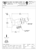
Theory of Operation
SmartWare shot dispense kits do not use flowmeters in
the material path to measure the volume pumped.
Instead the kit measures the volume pumped by using
the following calculation. See F
IG. 1 for a graphical rep-
resentation.
Area of the pump piston x distance traveled (measured
by the linear sensor) = volume pumped
When the system receives the start signal, the dispense
valve opens. Once the correct distance is traveled,
which equates to the desired shot volume, the dispense
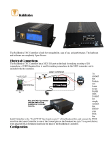
valve closes and the pump stalls.
Just like a car does not stop the instant you push on the
brake, the SmartWare kit pump does not stop pumping
the instant it receives a stop signal. Therefore, during
the time it takes for the dispense valve to physically
close fluid is still being pumped; the volume pumped
during this time is called the overshoot volume. See F
IG.
2 for a a graphical representation.
The SmartWare kit automatically compensates for over-
shoot by taking previous shots into consideration and
then sending the stop signal early.
The pressure transducer compensates for pump travel
during changeovers. Since only a few shots end in a
changeover, this compensation will take longer than the
basic overshoot compensation.
FIG. 1: Volume Pumped
Distance
Area
Volume pumped = Area x Distance
FIG. 2: Overshoot Volume
Overshoot
Volume
Stop Position
Stop Signal
Start Signal

Component Identification
8 3A0294G
Component Identification
Key:
A Lift Ring
B Air Motor
C* Display Module
D Air Controls
E* Air Solenoid (under shroud)
F* Power Supply (under shroud)
G* Power Switch (within shroud)
H Displacement Pump
JWet Cup
K Fluid Outlet
L Fluid Inlet
M Platen Bleed Port
NPlaten
RRam
S* Air Valve Assembly
T* Pressure Sensor Assembly
U* Linear Sensor Assembly
* Included in SmartWare kits.
FIG. 3: Component Identification
R
A
B
C*
J
K
H
M
D
N
E*, F*, G*
SmartWare Kit for D200 and D60 Rams
SmartWare Kit for S20 Rams
S*
T*
B
C*
S*
E*, F*, G*
D
R
J
K
H
M
N
T*
U*

Component Identification
3A0294G 9
Component Identification (cont.)
Key:
A Lift Ring
B Air Motor
C* Display Module
D Air Controls
E* Air Solenoid (under shroud)
F* Power Supply (under shroud)
G* Power Switch (within shroud)
H Displacement Pump
JWet Cup
K Fluid Outlet
L Fluid Inlet
P Floor Mount Stand
T* Pressure Sensor Assembly
V* Valve Assembly
* Included in SmartWare kits.
FIG. 4: Component Identification
SmartWare Kit for Wall Mount Pumps
J
A
C*
B
K
H
L
E*, F*, G*
SmartWare Kit for Floor Mount Pumps
E*, F*, G*
C*
A
B
J
K
L
H
P
D
V*
T*

Component Identification
10 3A0294G
User Interface
FIG. 5: Display Module
NOTICE
To prevent damage to soft key buttons, do not press
the buttons with sharp objects such as pens, plastic
cards, or fingernails.
Table 1: Display Module Button Functions
Button Function
Mode Select between Run and Setup modes.
Shot Start the present operation mode. Possible operation modes: shot mode, sequence mode,
manual mode, and park mode
Arrows Up/Down Navigate up or down within a screen or to a new screen.
Soft Keys Soft keys activate the mode or action represented by the icon next to each soft key.
See Table 2 for soft key icons and actions.
Top Soft Key: Turn air solenoid on/off, pause shot, continue shot, edit data, accept edited data,
or move right within a number field.
Bottom Soft Key: Enter a screen, exit a screen, cancel a shot, or cancel edited data.

Component Identification
3A0294G 11
Table 2: Display Soft Key Icons
Icon Function
Enter Screen In screens that have editable fields, press to access the fields and make changes.
Exit Screen In screens that have editable fields, press to exit edit mode.
Enter In screens that have editable fields, press to make data selections or to enter changes.
Right In screens that have editable fields, press to move to the right while in a field.
Cancel Cancel a selection or edited data. Returns to the original data. Cancel a shot when the shot is
active.
Reset Reset the selected field or value.
Pause Pause the shot that is currently active.
Continue Continue the shot that is currently active.
Air On/Off Turn the air valve on and off.
Start Process Start the automatic calibration process.

Component Identification
12 3A0294G
User Interface Display
For details regarding the user interface display, see , page 92.
Display Screen Components
The following figures call out the navigational, status, and general informational components of each display screen.
FIG. 6: Setup Mode Screen Components
}
Soft Keys
Enter/Exit Screen
Setup fields spe-
cific to current
setup screen
Scroll up
through screens
Current setup
screen number
Scroll down
through screens
FIG. 7: Run Mode Screen Components
Pause Shot
Cancel
Shot Progress Bar Graph
Current Mode
Pump or Dispense Valve
Run Screen in Shot Mode Shown
}
Soft Keys
{
Information
specific to current
run screen mode
(Air on- shaded)
(Air off - not shaded)


Component Identification
14 3A0294G
Run Mode Screen Structure
There are only two run mode screens: run and information. However, there are four modes within the run screen:
shot, sequence, manual and park. The following figure demonstrates the flow of the modes in the run screen begin-
ning with power up screen 1. For details on each run mode, see - Run Mode Details on page 100.
Run Screen - Shot Mode
Run Screen - Sequence Mode
Run Screen - Manual Mode
Run Screen - Park Mode
Information Screen
Dispense a Shot
Dispense a Shot Sequence
Power Up Screen
Enter screen to
dispense a shot
Enter screen to
dispense a shot
sequence

Grounding
3A0294G 15
Grounding
Supply System: ground the supply system as
instructed in the grounding section of the Supply Sys-
tems Operation manual.
Pump: use a ground wire and clamp. Connect the
ground wire to the ground stud on the air motor. Con-
nect ground clamp to a true earth ground.
Air and fluid hoses: use only electrically conductive
hoses.
Air compressor: follow manufacturer’s recommenda-
tions.
Dispense valve: ground through connection to a prop-
erly grounded fluid hose and pump. See dispense valve
manual for instructions and guidelines.
Fluid supply container: follow local code.
Solvent pails used when flushing: follow local code.
Use only conductive metal pails, placed on a grounded
surface. Do not place the pail on a nonconductive sur-
face, such as paper or cardboard, which interrupts
grounding continuity.
To maintain grounding continuity when flushing or
relieving pressure: hold metal part of the dispense
valve firmly to the side of a grounded metal pail, then
trigger the valve.
The equipment must be grounded. Grounding
reduces the risk of static and electric shock by
providing an escape wire for the electrical current due
to static build up or in the event of a short circuit. To
reduce the risk of static sparking, ground the pump,
the object being dispensed to, and all other
dispensing equipment used or located in the
dispensing area. All electrical wiring must be done by
a qualified electrician and comply with local codes
and regulations.
FIG. 8
TI8250a
FIG. 9
TI1102-2
TI1102-1

Installation
16 3A0294G
Installation
The procedures in this section are specific to each shot
dispense kit. Follow only the installation instructions for
your particular kit.
For supply system or pump assembly installation
instructions, refer to the Supply Systems Operation
manual or your pump packages instructions-parts man-
ual.
Location
NOTE: SmartWare Shot Dispense kits are not approved
for use in explosive atmospheres.
Follow the location guidelines and instructions provided
in the Supply Systems Operation manual or your pump
packages instructions-parts manual before installing the
shot dispense kit.
Install Kits 262370 and 262372
1. Close both shutoff valves on the air control panel.
2. Install the power supply bracket (33) to the ram post
using four screws (29) and lock washers (28).
FIG. 10: Close Shutoff Valves
FIG. 11: Install Power Supply Bracket
Shutoff
Valve
Shutoff
Valve
33
28
29
r_262370_3A0294_6a

Installation
3A0294G 17
3. Install the electronics subassembly (1) to the side of
the power supply bracket using four screws (34).
Also secure the bracket to the bottom of the air con-
trol bracket using two screws (29) and two lock
washers (28).
4. Install the light tower bracket (31) to the top air con-
trols bracket using three screws (29) and lock wash-
ers (28).
5. Loosen two screws on the top air controls bracket.
Install the display module bracket (2) using two
screws (29) and lock washers (28) to secure it to the
air controls bracket.
6. Install the air valve subassembly (3).
a. Use two wrenches to remove the air hose,
elbow fitting, and pressure gauge from the air
controls.
b. Remove the air motor slider valve label. See
F
IG. 15.
FIG. 12: Install Electronics Assembly
FIG. 13: Install Light Tower Bracket
1
34
29
28
r_262370_3A0294_7a
31
28
29
r_262370_3A0294_8a
FIG. 14: Install Display Module Bracket
FIG. 15: Air Control Assembly
2
29
28
r_262370_3A0294_9a
Air Hose
Label
Elbow
Fitting
Pressure
Gauge

Installation
18 3A0294G
c. Loosely install the air valve assembly (3).
Grease the o-ring included with the air valve
assembly. Install the o-ring and then finish
installing the air valve assembly. Secure with
screw.
d. Install the new air motor slider valve label that is
included with the air valve assembly. See F
IG.
15.
e. Coat the gauge fitting with PTFE tape, and then
reinstall. Use a wrench to tighten. See F
IG. 15.
f. Coat the swivel fitting (32) with PTFE tape.
Install the fitting and air hose on the back of the
new air valve assembly. Use two wrenches to
tighten.
7. Install the linear sensor assembly (18) and the reed
switch sensor (22).
a. D200 systems only: disconnect the air motor.
Loosen nut below crossbar. Use wrench to hold
thread adapter in place and loosen threaded rod
above crossbar with another wrench.
b. Remove the air motor top cover using a flat
head screwdriver.
FIG. 16: Install Air Valve Assembly
FIG. 17: Install Swivel Fitting
3
O-ring
Screw
r_262370_3A0294_11a
Slider Valve
Label
32
FIG. 18: Disconnect Air Motor
FIG. 19: Remove Air Motor Cover
Nut
Lift Ring
Adapter
Rod
ti10649a
Lift Ring
Plate
Thread
Adapter
ti8218b

Installation
3A0294G 19
c. Use a wrench to remove the air motor lift ring.
Then remove the lift ring adapter and both
o-rings. Discard the adapter and both o-rings.
d. Place the linear sensor magnet (13) on the
installation tool (27), and then insert the magnet
down into the top of the motor shaft.
e. Apply the supplied adhesive to the linear sensor
assembly (18) threads. Install the linear sensor;
torque to 30-36 ft-lbs (40.6-48.8 N•m). See F
IG.
21.
f. Place the new o-ring (20) on the lift ring adapter
(19), and apply the supplied adhesive to the
threads. See F
IG. 21.
g. Route the linear sensor cable through the lift
ring adapter. Install the lift ring adapter; torque
to 30-36 ft-lbs (40.6-48.8 N•m). See F
IG. 21.
h. Route the linear sensor cable through the hole
on the lift ring adapter.
i. Apply the supplied adhesive to the lift ring
threads. Install the lift ring; torque to 30-36 ft-lbs
(40.6-48.8 N•m). See F
IG. 21.
j. Remove the screw on the valve cover to remove
the cover. See F
IG. 22.
k. Install the reed switch sensor (22). Secure with
the 1 in. (25 mm) screw (24) and o-ring (23) pro-
vided. See F
IG. 22.
FIG. 20: Remove Lift Ring Adapter and O-rings
FIG. 21: Install Linear Sensor
r_262373_3A0294_before _linear
O-rings
Adapter
Lift Ring
13
18
19
Lift Ring
20
r_262373_3A0294_after_linear
FIG. 22: Install Reed Switch Sensor
Screw
Cover
24
23
22
r_262370_3A0294_16a

Installation
20 3A0294G
l. Connect the strain relief guide (26) to the reed
switch sensor. Use a wrench to tighten the
1/4-20 x 1/2 in. screw (25) on the strain relief
guide and to secure it to the top plate of the air
motor.
m. Use a zip tie to secure the reed switch sensor
cable.
n. Reinstall the valve cover, and tighten the nut.
See F
IG. 22.
o. Remove the plug in the air motor cover. Route
the linear sensor cables through the hole in the
back of the cover. Snap the air motor cover back
into place.
p. D200 systems only: reconnect the air motor.
Install threaded rod through center hole in the
crossbar. Install lock washers and nuts onto
threaded rod, both above and below crossbar.
Use wrench to hold lift ring adapter and tighten
threaded rod into lift ring adapter using another
wrench. Tighten nut below crossbar to 25 ft-lb
(34 N•m) maximum. Tighten nut above crossbar
to lock motor in place.
8. Install the pressure sensor on the pump bleed port.
D60 rams only: If pump bleed valve is longer than
the supplied, replace it with the supplied bleed valve
(65).
a. Use a wrench to remove the pressure valve.
FIG. 23: Install Strain Relief Guide
FIG. 24: Reinstall Air Motor Cover
25
26
Plug
r_262370_3A0294_17a
FIG. 25: Reconnect Air Motor
FIG. 26: Remove Pressure Valve
Rod
Nut
Nut
Washer
Lift Ring
Adapter
ti11169a
Pressure Valve
r_262370_3A0294_19a
/