Page is loading ...

309790ZAA
ENG
Instructions - Parts
TI2761A
Fixed-ratio proportioner shown
8900 Proportioner
Configured product offering for dispensing fixed or variable ratio of two
fluids. For professional use only.
Not approved for use in European explosive atmosphere locations.
2000 psi (13.8 MPa, 138 bar) Maximum Working Pressure
Important Safety Instructions
Read all warnings and instructions in this manual.
Save these instructions.
See page 8 for pump model numbers, ratios and
working pressures.

2 309790ZAA
Contents
Warnings . . . . . . . . . . . . . . . . . . . . . . . . . . . . . . . . . 4
Theory of Operation . . . . . . . . . . . . . . . . . . . . . . . . 6
Use . . . . . . . . . . . . . . . . . . . . . . . . . . . . . . . . . . . 6
Major Components . . . . . . . . . . . . . . . . . . . . . . . 6
Ratio Proportioning . . . . . . . . . . . . . . . . . . . . . . . 6
System Components and Operation Overview . . 6
Models . . . . . . . . . . . . . . . . . . . . . . . . . . . . . . . . . . . 8
Installation . . . . . . . . . . . . . . . . . . . . . . . . . . . . . . . 10
Typical Installation . . . . . . . . . . . . . . . . . . . . . . . 10
Location . . . . . . . . . . . . . . . . . . . . . . . . . . . . . . 10
Ground . . . . . . . . . . . . . . . . . . . . . . . . . . . . . . . 12
Flush . . . . . . . . . . . . . . . . . . . . . . . . . . . . . . . . . 13
Setup . . . . . . . . . . . . . . . . . . . . . . . . . . . . . . . . . . . . 14
Set the Ratio (variable ratio models only) . . . . . 14
Output Charts/Ratio Settings . . . . . . . . . . . . . . 15
Before You Load Material . . . . . . . . . . . . . . . . . 18
Load Component A . . . . . . . . . . . . . . . . . . . . . . 19
Prime Pump A . . . . . . . . . . . . . . . . . . . . . . . . . . 20
Load Component B . . . . . . . . . . . . . . . . . . . . . . 21
Prime with Component B . . . . . . . . . . . . . . . . . 24
Fill the 8900 Proportioner with Material . . . . . . 24
Operation . . . . . . . . . . . . . . . . . . . . . . . . . . . . . . . . 27
Pressure Relief Procedure . . . . . . . . . . . . . . . . 27
Dispense Mixed Material . . . . . . . . . . . . . . . . . . 28
Changing Component A Drum . . . . . . . . . . . . . 30
Changing Component B Pail . . . . . . . . . . . . . . . 31
Filling Component B Pressure Tank . . . . . . . . . 32
Daily Procedures . . . . . . . . . . . . . . . . . . . . . . . . 34
Troubleshooting . . . . . . . . . . . . . . . . . . . . . . . . . . . 36
8900 Proportioner Operating Pressures . . . . . . 36
Air Supply Troubleshooting Chart . . . . . . . . . . . 37
Pump Troubleshooting Overview . . . . . . . . . . . 38
Troubleshooting Guide: Feed pumps . . . . . . . . 39
Troubleshooting Guide: 8900 Proportioner . . . . 40
Troubleshooting Guide: Manifold/Mixer . . . . . . . 41
Preventive Maintenance . . . . . . . . . . . . . . . . . . 42
Service and Repair . . . . . . . . . . . . . . . . . . . . . . . . 43
Repair the Cylinder (Fixed Ratio) . . . . . . . . . . . 43
Replace Air Valve . . . . . . . . . . . . . . . . . . . . . . . 45
Disassemble Fluid Valve . . . . . . . . . . . . . . . . . . . . 46
Parts . . . . . . . . . . . . . . . . . . . . . . . . . . . . . . . . . . . . 48
8900 Proportioner, Fixed Ratio . . . . . . . . . . . . . 48
8900 Proportioner, Variable Ratio . . . . . . . . . . . 50
Cylinder Assemblies . . . . . . . . . . . . . . . . . . . . . 52
Limit Valve . . . . . . . . . . . . . . . . . . . . . . . . . . . . . 53
Air Control . . . . . . . . . . . . . . . . . . . . . . . . . . . . . 54
4-Way Valve . . . . . . . . . . . . . . . . . . . . . . . . . . . . 55
Pump Feed Module Selection for Component A or
Component B . . . . . . . . . . . . . . . . . . . . . . . 56
20:1 President on 5 Gallon Ram . . . . . . . . . . . . 56
34:1 Senator on 5 Gallon Ram . . . . . . . . . . . . . 58
23:1 Monark on 5 Gallon Ram . . . . . . . . . . . . . 60
20:1 President on 55 Gallon Ram . . . . . . . . . . . 62
34:1 Senator on 55 Gallon Ram . . . . . . . . . . . . 64
31:1 Bulldog on 55 Gallon Ram . . . . . . . . . . . . . 65
20:1 Senator on 55 Gallon Drum . . . . . . . . . . . . 66
9:1 DynaMite on 1 Gallon Can Ram . . . . . . . . . 67
10 Gallon Press Tank with 15:1 Booster . . . . . . 68
10:1 President 5 Gallon Pail Cover . . . . . . . . . . 69
Mix Kit Selection . . . . . . . . . . . . . . . . . . . . . . . . 70
Cartridge Fill Medium Viscosity Wide Ratio . . . 70
Cartridge Fill High Viscosity Wide Ratio . . . . . . 72
Brush Grade High Viscosity Wide Ratio . . . . . . 74
MD2 20 ft Automatic . . . . . . . . . . . . . . . . . . . . . 76
MD2 20 ft Hand Gun . . . . . . . . . . . . . . . . . . . . . 77
MD2 15 ft Hand Gun Wide Ratio Moisture Lock 78
High Volume Static Mix Manifold . . . . . . . . . . . . 79
High Volume Static Mix Kit with Pump Pilots . . . 80
Stanchion . . . . . . . . . . . . . . . . . . . . . . . . . . . . . . 81
Boom Assembly . . . . . . . . . . . . . . . . . . . . . . . . . 82
Technical Data . . . . . . . . . . . . . . . . . . . . . . . . . . . . 84
Graco Standard Warranty . . . . . . . . . . . . . . . . . . . 86
Graco Information . . . . . . . . . . . . . . . . . . . . . . . . . 86

309790ZAA 3

Warnings
4 309790ZAA
Warnings
Warning
Skin Injection Hazard
Spray from the gun, hose leaks, or ruptured components can inject fluid through skin and cause
extremely serious injury, including need for amputation. Fluid splashed in the eyes or on skin can cause
serious injury.
• Fluid injected into skin might look like just a cut, but it is a serious injury. Get immediate surgical
treatment.
• Do not point the gun at anyone or any part of the body.
• Do not put hand or fingers over the spray tip/nozzle.
• Do not stop or deflect leaks with hand, body, glove or rag.
• Do not “blow back” fluid; this is not an air spray system.
• Always have tip guard and trigger guard on the gun when spraying.
• Check gun diffuser weekly. Refer to gun manual.
• Check trigger safety operation before spraying. Lock trigger safety when you stop spraying.
• Follow the Pressure Relief Procedure, page 27, if the spray tip/nozzle clogs and before cleaning,
checking or servicing the equipment.
• Tighten fluid connections before operating equipment.
• Check hoses, tubes, and couplings daily. Replace worn or damaged parts immediately. Do not repair
high pressure couplings; replace the entire hose.
• Fluid hoses must have spring guards on both ends to help protect them from rupture caused by kinks
or bends near the couplings.
Toxic Fluid Hazard
Hazardous fluids or toxic fumes can cause serious injury or death if splashed in the eyes or on skin, swal-
lowed, or inhaled.
• Know specific hazards of the fluid. Read fluid manufacturer’s warnings.
• Wear appropriate protective clothing, gloves, eyewear, and respirator.

Warnings
309790ZAA 5
Warning
Equipment Misuse Hazard
Equipment misuse can cause equipment to rupture, malfunction, or start unexpectedly and cause serious
injury.
• This equipment is for professional use only.
• Read manuals, tags, and labels before operating equipment.
• Use equipment only for its intended purpose. If you are uncertain, call your Graco distributor.
• Do not alter or modify equipment. Use only genuine Graco parts and accessories.
• Check equipment daily. Repair or replace worn or damaged parts immediately.
• Do not exceed maximum working pressure of lowest rated system component.
• Use fluids and solvents that are compatible with equipment wetted parts. See Technical Data sec-
tion of all equipment manuals. Read fluid and solvent manufacturer’s warnings.
• Route hoses away from traffic areas, sharp edges, moving parts, and hot surfaces. Do not expose
Graco hoses to temperatures above 180°F (82°C) or below -40°F (-40°C).
• Do not kink or overbend hoses or use hoses to pull equipment.
• Comply with all applicable local, state, and national fire, electrical, and other safety regulations.
• Do not use excessive drum separation air pressure as the drum could rupture. Make sure the drum is
not damaged and the ram plate is free to exit the drum before applying air pressure.
Fire and Explosion Hazard
Improper grounding, poor ventilation, open flames or sparks can cause a hazardous condition and result
in fire or explosion and serious injury.
• Ground the equipment and object being sprayed. See Grounding, page 12.
• If you experience static sparking or electric shock, stop operation immediately. Identify and correct
the problem.
• Provide fresh air ventilation to avoid building up flammable fumes.
• Keep the spray area free of debris, including solvent, rags, and gasoline.
• Extinguish all sources of flames in the spray area, including pilot lights and cigarettes.
• Do not turn on or off any light switch or plug or unplug electrical equipment in the spray area while
operating or if fumes are present.
• Do not operate a gasoline engine in the spray area.
• Keep a fire extinguisher in the work area.
Moving Parts Hazard
Moving parts, such as priming piston and wiper plate, can pinch or amputate fingers. Keep clear of mov-
ing parts when starting or operating equipment and when equipment is pressurized.
• Keep hands and fingers away from the priming piston.
• Keep hands away from the ram wiper plate and pail lip.
• Before servicing, follow the Pressure Relief Procedure, page 27, to avoid equipment startup.

Theory of Operation
6 309790ZAA
Theory of Operation
Use
The 8900 Proportioner is used with two component
materials where one or both components is high viscos-
ity. This is typically found in the sealant and adhesive
industry, where special requirements for loading and
pumping necessitate the use of the 8900 proportioning
system.
Major Components
The major components of the 8900 Proportioner system
include the:
• Component A or major volume metering cylinder
• Component B or minor volume metering cylinder
• Component A or major volume feed supply
• Component B or minor volume feed supply
Ratio Proportioning
The A and B cylinders are positive displacement meter-
ing cylinders. Positive displacement cylinders displace a
defined volume of fluid for a given stroke length.
On fixed ratio units, the volumetric ratio is the ratio of the
area of the component A displacement cylinder to the
area of the component B displacement cylinder. At a 1:1
ratio, the displacement cylinders are the same size. On
higher ratio units the component A cylinder is usually the
larger of the two. The ratio of the components is the dif-
ference in effective area between the cylinders.
On variable ratio units, the component B cylinder has an
adjustable stroke length. The component A cylinder has
a fixed stroke length. By setting the stroke adjustment to
different points on the connecting linkage, you can
change the stroke length of the B cylinder, which
changes the mix ratio. You can calculate the material
mix ratio from the ratio of the cylinder displacement vol-
ume.
Note that the mix ratio of the 8900 Proportioner is
achieved by volumetric ratio of component A to compo-
nent B and not by weight. These two ratios are often dif-
ferent depending on material properties.
System Components and
Operation Overview
Feed Systems - Feed Pumps
Load the Feed Pumps and Proportioner
The A and B feed pumps/cylinders must completely fill
(prime) on both strokes to ensure accurate material dis-
placement.
With high viscosity materials, it is difficult for material to
flow into the pump. Individual feed pumps are used to
supply these materials under pressure to the 8900 Pro-
portioner. When air is trapped in the feed system due to
improper loading, a condition called cavitation occurs.
If cavitation occurs, part of the downstroke will be used
to fill the vacuum before any material is actually dis-
placed. Since the total stroke length is used to calculate
mix ratio, this may result in an off-ratio condition.
To prevent cavitation with higher viscosity materials,
both cylinders are pressure fed. The A pump is pressur-
ized by a pneumatic ram supply unit applying a down-
ward force on a 55-gallon plate fitted into the drum. A
shovel action pump fluid inlet further aids in pump prim-
ing. Component B is delivered to the B pump by pres-
sure fed 5- or 55-gallon supply modules, depending on
the volumetric ratio of the material.
Pneumatic ram assisted feed pumps may not be
required for lower viscosity materials.
Feed Systems - Alternative Feed Supplies
Header or other feed systems may be used to supply A
and B materials to the 8900 Proportioner. Generally
these feed systems are provided by others and are not
addressed in this manual. This manual applies only to
the Graco Configured 8900 Proportioner system.

Theory of Operation
309790ZAA 7
Pump Fluids to the Mixer
Fluid is pumped through the proportioner to a mix cham-
ber or to a 2-component dispense gun, where compo-
nent A and component B are first introduced before
being mixed with a static mixer.
A fluid injector nozzle/check valve injects component B
into component A at the mix chamber. When enough
pressure builds up, the check valve opens and compo-
nent B flows into the mix chamber. This means that dur-
ing flow conditions with two positive displacement
cylinders linked together, the pressures at the mix point
are equal.
Any pressure differences noted on the gauges while
running, reflect differences in the pressure lost by each
fluid getting from the gauge to the mix point. These
pressure drops are caused by hoses and fittings in con-
junction with material viscosity.
Mix the Fluids
Both components leave the mix chamber and enter a
static mixer where they are mixed to a homogeneous
blend. The mixer consists of a series of left and
right-hand spiral elements. This is true for both mix
chamber and 2-component mix gun.
When the components are pumped through the mixer,
they are progressively divided and recombined. Static
mixers used on the 8900 Proportioner system include
the tri-core mixer, flexible hose mixer, or disposable
mixer.
Ratio Checks
On the variable ratio model, a ratio check station option
verifies the volumetric mix ratio of the two components.
It is located at the outlet blocks. With all outbound fluid
valves closed, each component flows through individual
ball valves opened by a common handle into containers.
Volumetric mix ratio can be calculated from the weight of
each component or by direct measurement. Ratio
checks are performed with the back pressures set to
actual operating pressures to simulate the normal back
pressures created by the mix chamber and gun.
Dispense Valve
An extrusion flow gun is commonly used as the applica-
tion device. It has a final or clean up mixer installed in
the handle. Various extrusion nozzles are available for
caulking or sealing applications.
Some 8900 Proportioners use a 2K disposable mixer
element dispense valve instead of the flow gun.
The 8900 Proportioner can be used in automatic
assembly lines with the addition of a logic interface.

Models
8 309790ZAA
Models
Refer to form 684041 for selection information.
Model Description
890-D Power Valved Passive Proportioner
Code A Proportioner Selection (“A” Cyl. / “B” Cyl.) Module Number
1 1:1 Fixed (1000/1000) 570371
2 2:1 Fixed (1000/500) 570372
3 2.5:1 Fixed (250/100) 570373
4 4:1 Fixed (1000/250) 570374
5 5:1 Fixed (500/100) 570375
6 10:1 Fixed (1000/100) 570376
7 9:1 Fixed (1000/111) 246557
A 1:1 to 4:1 Variable (500/500) 570377
B 2:1 to 8:1 Variable (500/250) 570378
D 5:1 to 20:1 Variable (500/100) 570380
Code B Pump Feed Module Selection for Component A Module Number
A 20:1 President on 5 Gallon Ram 965571
B 34:1 Senator on 5 Gallon Ram 965597
C 23:1 Monark on 5 Gallon Ram 570142
D 20:1 President on 55 Gallon Ram 570114
E 34:1 Senator on 55 Gallon Ram 965572
F 31:1 Bulldog on 55 Gallon Ram 570141
G 20:1 Senator on 55 Gallon Drum 570309
H 9:1 DynaMite 1 Gallon Can Ram 570249
J 10 Gallon Press Tank with 15:1 Booster 570037
K 10:1 President 5 Gallon Pail Cover 570264
NNone
Code C Pump Feed Module Selection for Component B Module Number
A 20:1 President on 5 Gallon Ram 965571
B 34:1 Senator on 5 Gallon Ram 965597
C 23:1 Monark on 5 Gallon Ram 570142
D 20:1 President on 55 Gallon Ram 570114
E 34:1 Senator on 55 Gallon Ram 965572
F 31:1 Bulldog on 55 Gallon Ram 570141
G 20:1 Senator on 55 Gallon Drum 570309
H 9:1 DynaMite 1 Gallon Can Ram 570249
J 10 Gallon Press Tank with 15:1 Booster 570037
K 10:1 President 5 Gallon Pail Cover 570264
NNone

Models
309790ZAA 9
Code D Mix Kit Selection Module Number
1 Cart Fill Medium Viscosity Wide Ratio 570248
2 Cart Fill High Viscosity Wide Ratio 570318
3 Brush Grade High Viscosity Wide Ratio 570358
4 MD2 20 ft Automatic Wide Ratio 24H258
5 MD2 20 ft Automatic Close Ratio 24H259
6 MD2 20 ft Hand Gun Wide Ratio 24H260
7 MD2 20 ft Hand Gun Close Ratio 24H261
8 MD2 15 ft Hand Gun Wide Ratio Moisture Lock 24H243
9 High Volume Static Mix Kit with Pump Pilots 570263
NNone
Code E Mounting Type Selection Module Number
1 Stanchion 570071
2 Boom Assembly 246589
N None (mount on 3 in. 55 gallon ram)

Installation
10 309790ZAA
Installation
Typical Installation
Figures 1-3 are only guides for selecting and installing system components and accessories. Contact your
Graco distributor for assistance in designing a system to suit your needs.
Location
Position the feed modules so the pump and ram are
easily accessible. Ensure that there is sufficient over-
head clearance when the ram is fully raised. Refer to
the ram manual for clearance dimensions.
Using the holes in the ram base as a guide, drill four
holes for 1/2 in. (13 mm) anchors.
Check that the ram base is level in all directions. If
necessary, level the base using metal shims. Secure
the base to the floor using 1/2 in. (13 mm) anchors
that are long enough to prevent the ram from tipping.
Key:Figs. 1 and 2
A System Air Shutoff Valve (bleed-type)
B Main Air Filter
C Component B Ram Directional Valve
D Component B Ram Air Pressure Regulator
E Component B Air Supply Valve (bleed-type)
F Component B Air Supply Regulator
G Component A Air Supply Valve
H Component B Outlet Pressure Gauge
J Component B Feed Pressure Gauge
K Component A Feed Pressure Gauge
L Component A and Component B Feed Pump Air
Motor Lubricator
M Component B Ram Plate with Vent Stick or Valve
N Component A Ram Plate with Drum Vent Valve
O Component A Pump Air Regulator
P Component A Ram Directional Valve
Q MD2 Gun with Disposable Mixers
R Component A Ram Air Pressure Regulator
S Accessory/Gun Air Supply Valve
FIG. 1:
8900
PROPORTIONER
BASE PURGE AND SHUT-DOWN
REFILLING PRESSURE POT
READ MANUAL BEFORE OPERATING
(IF EQUIPPED)
DISPENSE MIXED MATERIAL
DRUM OR PAIL CHANGE
ADJUST FLOW RATE
"B" PUMP
PRESSURE
ADJUSTMENT
INSTRUCTIONS
INSTRUCTIONS
R
ONOFF
PUMPS
"A" PUMP
PRESSURE
ADJUSTMENT
Read instruction manual before operating. Observe all
High pressure device for professional use only.
warnings.
MAIN AIR
OFF ON
WARNINGWARNING
WARNINGWARNING
WARNINGWARNING
MAIN AIR
INLET
C
A
B
D
E
F
G
H
L
M
N
O
P
Q
R
(behind)
J
(behind)
K
S
ti16735a

Installation
309790ZAA 11
Key:FIG. 3
Q2K Gun
V Disposable Mixer Element
W Component B Injector Valve
X Air Trigger Pilot
Y Component B Supply
Z Component A Supply
FIG. 2:
8900
PROPORTIONER
BASE PURGE AND SHUT-DOWN
REFILLING PRESSURE POT
READ MANUAL BEFORE OPERATING
(IF EQUIPPED)
DISPENSE MIXED MATERIAL
DRUM OR PAIL CHANGE
ADJUST FLOW RATE
"B" PUMP
PRESSURE
ADJUSTMENT
INSTRUCTIONS
INSTRUCTIONS
R
ONOFF
PUMPS
"A" PUMP
PRESSURE
ADJUSTMENT
Read instruction manual before operating. Observe all
High pressure device for professional use only.
warnings.
MAIN AIR
OFF ON
WARNINGWARNING
WARNINGWARNING
WARNINGWARNING
MAIN AIR
INLET
A
B
H
L
(behind)
J
(behind)
K
S
Component B
Supply Header
Component A
Supply Header
Component A
Fluid Regulator
Component B
Fluid Regulator
Supply header system supplied by others
(not covered in this manual).
ti16759a
FIG. 3
V
Q
W
X
Y
Z
ti16737a

Installation
12 309790ZAA
Ground
Pump: use the ground wire and clamp (supplied). There
are two styles of ground connections on pump air
motors.
If you have the ground screw (a) shown in F
IG. 4
(King air motor only), order part no. 222011 ground wire,
ring terminal, and clamp assembly (b). To install
222011, remove the ground screw (a) and insert it
through the eye of ring terminal (c), then tighten ground
screw back into air motor as shown in F
IG. 4. Connect
the other end of the wire to a true earth ground.
If you have the ground screw (d) shown in F
IG. 5,
loosen the grounding lug locknut (g) and washer (f).
Insert one end of the ground wire (e) into the slot in lug
(d) and tighten the locknut securely. Connect the other
end of the wire to a true earth ground. Order 237569
ground wire and clamp assembly.
Air and fluid hoses: use only electrically conductive
hoses with a maximum of 500
ft (150 m) combined hose
length to ensure grounding continuity. Check the electri-
cal resistance of your air and fluid hoses. If the total
resistance to ground exceeds 29 megohms, replace the
hose immediately.
Air compressor: follow manufacturer’s recommenda-
tions.
Spray gun/dispense valve: ground through connection
to a properly grounded fluid hose and pump.
Fluid supply container: follow your local code.
Substrate: follow your local code.
Solvent pails used when flushing: follow your local
code. Use only conductive, metal pails, placed on a
grounded surface. Do not place the pail on a noncon-
ductive surface, such as paper or cardboard, which
interrupts grounding continuity.
To maintain grounding continuity when flushing or
relieving pressure: hold a metal part of the gun/dis-
pense valve firmly to the side of a grounded metal pail,
then trigger the gun/valve.
WARNING
The system must be properly grounded. Read warn-
ings, page 5. Follow the instructions below.
F
IG. 4: Ground Screw (King air motors only)
F
IG. 5 Ground Screw
b
a
c
g
f
e
d

Installation
309790ZAA 13
Flush
• The equipment was tested with light, soluble oil.
Flush the system before loading material to avoid
contamination.
• Flush at the lowest pressure possible and check
connectors for leaks.
To flush the system:
1. On the ram-mounted component A supply units, you
must remove the drum ram plate to immerse the A
pump in a solvent pail. To remove the plate:
a. Disconnect the blow-off air line from the ram
plate.
b. Disconnect the tie rod nuts from the ram cross
beam.
c. Remove seal plates between the pump and
ram.
d. Loosen ram tie rods from plate and remove
plate.
e. If a pail ram is used with the component B sup-
ply, remove the pail plate by loosening the 2 set
screws.
f. Position the solvent pail so the pump inlet is in
the solvent.
g. Support the ram(s) so that the pump inlet and
piston will not hit the base plate or pail bottom.
h. Make sure both component A and component B
outlet hoses are open.
2. Flush the system and all hoses by very slowly open-
ing the motor control valves until 30 psi (207 kPa,
2.1 bar) is shown on the component A outlet pres-
sure gauge.
Flush for 1-2 minutes, then close the motor control
valves.
3. Check connectors for leaks and tighten them if nec-
essary.
4. Remove the solvent pail(s) from the pump inlets.
5. Operate the pump(s) at low pressure to remove
excess solvent.
6. Reinstall the drum or pail ram plates.
WARNING
Read warnings, pages 4-5. Follow Ground instruc-
tions, page 12.
Use solvent that is compatible with the equipment
wetted parts and the material you will dispense.
CAUTION
To avoid damaging the pump, open the motor control
valves very slowly to prevent a pump runaway condition.
It is normal for the air valve to exhaust air when it is
partially open.

Setup
14 309790ZAA
Setup
Set the Ratio (variable ratio
models only)
Adjust ratio
The ratio of this unit is produced partially by the differ-
ence in the area of the metering cylinders and partially
by the position of the adjustable fulcrum point in the Uni-
bar linkage assembly. With the fulcrum point in the cen-
ter, each meter cylinder strokes 3 in. (10.16 cm). In the
center position, the dispense ratio is the same as the
meter cylinder ratio.
The linkage is adjustable depending on the location of
the fulcrum point. The linkage must be adjusted for each
material application so the combined linkage and meter
cylinder ratio equals the desired material mix ratio by
volume. The ratio may be checked by weight, but the
machine meters by volume and that ratio must be known
before proceeding.
The initial linkage adjustment point can be calculated by
inserting known values into the formula on page 35. The
result is the distance in inches from the center of the ful-
crum point to the center of the component B meter cylin-
der. For convenience, measure the distance between
the grease fitting on the top of the fulcrum and the cen-
ter of the component B cylinder meter rod.
Set Scale
Refer to the 8900 Proportioner Output Charts on the fol-
lowing pages to set the scale. Make final adjustments
after the material is loaded. See instructions on page 33
for detailed ratio check instructions.
WARNING
Read warnings, pages 4-5, before operating equip-
ment.
FIG. 6
B
V
o
l
u
m
e
D
e
c
r
e
a
s
e
I
n
c
r
e
a
s
e

Setup
309790ZAA 15
Output Charts/Ratio Settings
8900 Proportioner, 1:1 - 4:1 Variable Ratio
Mix Ratio by Volume Scale Setting Minor Stroke
1 5.63 3.00
1.5 7.13 2.00
2 8.13 1.50
2.5 8.85 1.20
3 9.38 1.00
3.5 9.80 0.86
4 10.13 0.75
0
2
4
6
8
10
12
Mix Ratio by Volume
Setting in Inches from Pivot or Minor Stroke
Scale Settin
g
5.63 7.13 8.13 8.85 9.38 9.80 10.13
Minor Stroke
3.00 2.00 1.50 1.20 1.00 0.86 0.75
1 1.5 2 2.5 3 3.5 4

Setup
16 309790ZAA
8900 Proportioner, 2:1 - 8:1 Variable Ratio
Mix Ratio by Volume Scale Setting Minor Stroke
2 5.63 3.00
3 7.13 2.00
4 8.13 1.50
5 8.85 1.20
6 9.38 1.00
7 9.80 0.86
8 10.13 0.75
0
2
4
6
8
10
12
Mix Ratio by Volume
Setting in Inches from Pivot or Minor Stroke
Scale Settin
g
5.63 7.13 8.13 8.85 9.38 9.80 10.13
Minor Stroke
3.00 2.00 1.50 1.20 1.00 0.86 0.75
2345678

Setup
309790ZAA 17
8900 Proportioner, 5:1 - 20:1 Variable Ratio
Mix Ratio by Volume Scale Setting Minor Stroke
5 5.63 3.00
7 7.13 2.00
10 8.13 1.50
12 8.85 1.20
15 9.38 1.00
17 9.80 0.86
20 10.13 0.75
0
2
4
6
8
10
12
Mix Ratio by Volume
Setting in Inches from Pivot or Minor Stroke
Scale Settin
g
5.63 7.13 8.13 8.85 9.38 9.80 10.13
Minor Stroke
3.00 2.00 1.50 1.20 1.00 0.86 0.75
5 7 10 12 15 17 20

Setup
18 309790ZAA
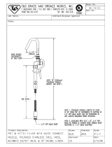
Before You Load Material
1. Check fluid and air lines and tighten if necessary.
2. Make sure there is a minimum overhead clearance
of 110 in. (279 cm) for 55 gallon supply.
3. Fill air line lubricator for the 8900 Proportioner mod-
ule with SAE 10 W non-detergent oil (not included).
4. Fill the pump A and B wet cups 2/3 full with Graco
T.S.L. fluid (throat seal lubricant) or lubricant com-
patible with material being pumped.
5. Close (turn fully counterclockwise) all air regulators.
6. Connect the 3/4 in. (19 mm) ID x 10 ft (3.05 m) air
hose (provided) to your air supply.
ISO pump oil is used with moisture sensitive com-
ponent B.
Do not use a restrictive quick-disconnect. The air
supply pressure must be consistently above the
pressure you set on the main air motor regulator.
F
IG. 7
G
N
Wet Cup
TI3263Ax

Setup
309790ZAA 19
Load Component A
1. Make sure all air regulators on proportioner module
are fully closed.
2. Open the main air supply shutoff valve (A), F
IG. 8.
3. Place the ram lever (P-F
IG. 10) in the UP position.
4. Slowly turn the ram air regulator (R) clockwise until
the ram begins rising.
5. When ram is fully raised, apply a thin coating of
lubricant to the ram plate drum seals.
6. Open the material container. Remove any packing
materials, and inspect for material contamination. If
the container has a plastic liner, pull it tightly over
the sides of the container, and secure the liner in
place with tape wrapped below the top drum rim.
7. Position the drum so it rests evenly between the
centering guides and is fully backed into the stops
located near the back of the ram base plate.
8. Open the drum vent valve (W), F
IG. 9.
9. With hands away from the pail and wiper plate (N),
set the ram lever (P-F
IG. 10) to NEUTRAL (horizon-
tal position). Let the ram lower until the wiper plate
rests on the pail lip.
10. Lower the ram plate into the drum (move ram lever
to DOWN position).
11. After the ram plate seals contact the drum, adjust
the ram air regulator (R) to about 30-50 psi
(207-345 kPa, 2.1-3.4 bar).
12. When the ram stops and material fills the bleed port
(or air stops bleeding out), close the drum vent valve
(W), F
IG. 9.
13. Supply unit is now ready to fill lines to proportioner.
CAUTION
As the ram rises, make sure hoses do not catch on any
components. If a hose catches, immediately stop the
ram (move lever to NEUTRAL position) and correct the
problem. Lower the ram if necessary to redirect hoses.
F
IG. 8
A
O
FIG. 9
WARNING
When lowering the ram, keep hands and body away
from the ram plate and material drum. Read warnings,
page 5.
CAUTION
Do not lower ram if a drum is not in place. Doing so can
damage drum centering guides.
FIG. 10
W
N
P
R
Ram Separation
Air Button

Setup
20 309790ZAA
Prime Pump A
1. Place a waste container under the pump bleed valve
located behind the displacement pump outlet, F
IG.
11. Using an adjustable wrench, open the bleed
valve counterclockwise 1/3-1/2 turn.
2. Slowly open the component A air motor shutoff
valve (G), F
IG. 7. Make sure the pump begins to
cycle and material flows from the bleed valve after
several cycles of the pump, F
IG. 11.
3. Operate the pump until it moves smoothly in both
directions with no air popping or erratic movement,
then close the air motor shutoff valve (G).
4. Close the bleed valve, F
IG. 11.
F
IG. 11
Bleed Valve
If the pump does not cycle, close the air shutoff
valve (G), adjust the air motor regulator (O-F
IG. 8)
up 5 psi (34 kPa, 0.3 bar) and repeat step 2.
Never adjust the regulator by more than 5 psi (34
kPa, 0.3 bar) increments.
/