Page is loading ...


1.03-10312014-140100
USER MANUAL
Video Wall Mini
Fanless and Slim size system with
4-display HDMI support

Tested To Comply
With FCC Standards
FOR HOME OR OFFICE USE
Copyright
Copyright © 2014 VIA Technologies Incorporated. All rights reserved.
No part of this document may be reproduced, transmitted, transcribed, stored in a retrieval system, or translated into any language,
in any form or by any means, electronic, mechanical, magnetic, optical, chemical, manual or otherwise without the prior written
permission of VIA Technologies, Incorporated.
Trademarks
All trademarks are the property of their respective holders.
Disclaimer
No license is granted, implied or otherwise, under any patent or patent rights of VIA Technologies. VIA Technologies makes no
warranties, implied or otherwise, in regard to this document and to the products described in this document. The information
provided in this document is believed to be accurate and reliable as of the publication date of this document. However, VIA
Technologies assumes no responsibility for the use or misuse of the information (including use or connection of extra
device/equipment/add-on card) in this document and for any patent infringements that may arise from the use of this document.
The information and product specifications within this document are subject to change at any time, without notice and without
obligation to notify any person of such change.
VIA Technologies, Inc. reserves the right the make changes to the products described in this manual at any time without prior
notice.
Regulatory Compliance
FCC
FCCFCC
FCC-
--
-A Radio Frequency
A Radio FrequencyA Radio Frequency
A Radio Frequency Interference Statement
Interference Statement Interference Statement
Interference Statement
This equipment has been tested and found to comply with the limits for a class A digital device, pursuant to part 15 of the FCC
rules. These limits are designed to provide reasonable protection against harmful interference when the equipment is operated in a
commercial environment. This equipment generates, uses, and can radiate radio frequency energy and, if not installed and used in
accordance with the instruction manual, may cause harmful interference to radio communications. Operation of this equipment in a
residential area is likely to cause harmful interference, in which case the user will be required to correct the interference at his
personal expense.
Notice 1
Notice 1Notice 1
Notice 1
The changes or modifications not expressly approved by the party responsible for compliance could void the user's authority to
operate the equipment.
Notice 2
Notice 2Notice 2
Notice 2
Shielded interface cables and A.C. power cord, if any, must be used in order to comply with the emission limits.
Notice 3
Notice 3Notice 3
Notice 3
The product described in this document is designed for general use, VIA Technologies assumes no responsibility for the conflicts
or damages arising from incompatibility of the product. Check compatibility issue with your local sales representatives before
placing an order.

Battery Recycling and Disposal
Only use the appropriate battery specified for this product.
Do not re-use, recharge, or reheat an old battery.
Do not attempt to force open the battery.
Do not discard used batteries with regular trash.
Discard used batteries according to local regulations.
Safety Precautions
Always read the safety instructions carefully.
Keep this User's Manual for future reference.
All cautions and warnings on the equipment should be noted.
Keep this equipment away from humidity.
Lay this equipment on a reliable flat surface before setting it up.
Make sure the voltage of the power source and adjust properly 110/220V before connecting
the equipment to the power inlet.
Place the power cord in such a way that people cannot step on it.
Always unplug the power cord before inserting any add-on card or module.
If any of the following situations arises, get the equipment checked by authorized service
personnel:
The power cord or plug is damaged.
Liquid has penetrated into the equipment.
The equipment has been exposed to moisture.
The equipment has not worked well or you cannot get it work according to User's Manual.
The equipment has dropped and damaged.
The equipment has obvious sign of breakage.
Do not leave this equipment in an environment unconditioned or in a storage temperature
above 60°C (140°F). The equipment may be damaged.
Do not leave this equipment in direct sunlight.
Never pour any liquid into the opening. Liquid can cause damage or electrical shock.
Do not place anything over the power cord.
Do not cover the ventilation holes. The openings on the enclosure protect the equipment
from overheating

Video Wall Mini User Manual
Video Wall Mini User ManualVideo Wall Mini User Manual
Video Wall Mini User Manual
iv
Box Contents
ATG
ATGATG
ATG-
--
-A1400
A1400A1400
A1400-
--
-3Q10A1
3Q10A13Q10A1
3Q10A1
1 x Video Wall Mini system unit
1 x Power cord, 180 cm, Japan Type
1 x Power adaptor, 12V/8.5A 102W
1 x Power cable, 4-hole DC-In jack
2 x HDMI cable strap holder
4 x SATA SSD screws
4 x Mounting screws
2 x Screws for Mini card (module) installation
1 x 0.392cc thermal grease in tube syringe
VIA MagicView content management software (Multi-language/default English ver.)

Video Wall Mini User Manual
Video Wall Mini User ManualVideo Wall Mini User Manual
Video Wall Mini User Manual
v
Ordering Information
Part Number
Part NumberPart Number
Part Number
Description
DescriptionDescription
Description
ATG
ATGATG
ATG-
--
-A1400
A1400A1400
A1400-
--
-3Q10A1
3Q10A13Q10A1
3Q10A1 Fanless Embedded System with 1.0+GHz VIA QuadCore
processor, 4 x HDMI
®
, 2 x USB 2.0, 2 x USB 3.0, 1 x GigaLAN, 1 x
COM (RS-232), 1 x Digital I/O, HD Audio (Line-In and Line-Out) 1
x SATA SSD bay and DC-In 12V, power cord Japan type.
Optional Accessories
Peripherals
PeripheralsPeripherals
Peripherals
Model Number
Model NumberModel Number
Model Number
Description
DescriptionDescription
Description
EMIO-1533-00A2 802.11 b/g/n Wireless LAN USB Module
EMIO-1541-00A1 HSPA/WCDMA/EDGE/GPRS mobile broadband Mini PCIe Card
Module
External AC
External ACExternal AC
External AC-
--
-to
toto
to-
--
-DC Adapter and
DC Adapter and DC Adapter and
DC Adapter and Power C
Power CPower C
Power Cord
ordord
ord
Model Number
Model NumberModel Number
Model Number
Description
DescriptionDescription
Description
99G33-020316 AC-to-DC adaptor, 12V/8.5A 102W
99G33-02032C Power Cord, 180 cm, USA type
99G33-02033C Power Cord, 180 cm, Europe type
99G33-02034C Power Cord, 180 cm, Japan type
99G33-02103C Power Cord, 180 cm, China type

Video Wall Mini User Manual
Video Wall Mini User ManualVideo Wall Mini User Manual
Video Wall Mini User Manual
vi
Table of Contents
1.
1.1.
1.
Product Overview
Product OverviewProduct Overview
Product Overview................................
................................................................
................................................................
................................................................
................................................................
................................................................
................................ 1
11
1
1.1.
Key Features................................................................................................... 1
1.1.1.
Powered by VIA
®
QuadCore Processor............................................... 1
1.1.2.
Fanless and Rugged Chassis.................................................................... 1
1.1.3.
Multiple Display Support...................................................................... 2
1.1.4.
Optimize Integration with Multiple I/O Access .............................. 2
1.1.5.
Storage Expansion .................................................................................. 2
1.1.6.
Wide Range of Operating Temperatures........................................... 2
1.1.7.
Shock Resistant ........................................................................................ 2
1.1.8.
Networking Support............................................................................... 2
1.1.9.
Embedded OS ready ............................................................................. 2
1.2.
Product Specifications................................................................................. 3
1.3.
Panel Layout .................................................................................................. 7
1.4.
Dimensions .................................................................................................... 9
2.
2.2.
2.
External I/O Pin Descriptions and Functionality
External I/O Pin Descriptions and FunctionalityExternal I/O Pin Descriptions and Functionality
External I/O Pin Descriptions and Functionality................................
................................................................
.............................................
..........................
............. 11
1111
11
2.1.
Front Panel I/O............................................................................................ 11
2.1.1.
DC-In Jack (Power Input) .................................................................... 11
2.1.2.
Power Button ......................................................................................... 11
2.1.3.
HDMI
®
Port............................................................................................. 12
2.1.4.
LED Indicators (Power LED and SATA SSD LED) .......................... 13
2.1.5.
RJ-45 LAN Port (Gigabit Ethernet) .................................................... 14
2.1.6.
Audio Jacks............................................................................................. 15
2.1.7.
USB 3.0 Port ........................................................................................... 15
2.2.
Right Side Panel.......................................................................................... 16
2.2.1.
LED Indicators (3G/3.5G and WLAN)................................................ 16
2.2.2.
Digital I/O Connector .......................................................................... 16
2.2.3.
USB 2.0 Port ........................................................................................... 17
2.2.4.
COM Connector.................................................................................... 18
3.
3.3.
3.
Onboard Connector and Pin Headers
Onboard Connector and Pin HeadersOnboard Connector and Pin Headers
Onboard Connector and Pin Headers................................
................................................................
.............................................................
..........................................................
............................. 19
1919
19
3.1.
LPC Connector ............................................................................................ 19
3.2.
VGA Pin Header ......................................................................................... 20
3.3.
SPI Pin Header............................................................................................. 21
3.4.
System Temperature Sensor Pin Header............................................... 22
4.
4.4.
4.
Onboard Jumpers
Onboard JumpersOnboard Jumpers
Onboard Jumpers ................................
................................................................
................................................................
................................................................
..............................................................
............................................................
.............................. 23
2323
23
4.1.
System Reset Jumper................................................................................. 24

Video Wall Mini User Manual
Video Wall Mini User ManualVideo Wall Mini User Manual
Video Wall Mini User Manual
vii
4.2.
Reset CMOS RAM Jumper........................................................................ 25
4.3.
SPI Address Select Jumper ...................................................................... 26
4.4.
Recovery BIOS Jumper.............................................................................. 27
4.5.
VDD/VSUSVDD Mode Select Jumper................................................... 28
5.
5.5.
5.
Hardware Installation
Hardware InstallationHardware Installation
Hardware Installation ................................
................................................................
................................................................
................................................................
........................................................
................................................
........................ 29
2929
29
5.1.
How to remove the top cover ................................................................ 29
5.2.
How to reinstall the top cover ............................................................... 30
5.3.
How to install the DDR3 SODIMM memory ....................................... 32
5.4.
How to remove the DDR3 SODIMM memory..................................... 33
5.5.
How to install the 2.5-inch SATA SSD ................................................. 34
5.6.
How to install the mSATA module ....................................................... 36
5.7.
How to insert SIM card............................................................................. 37
5.8.
How to install 3G/3.5G module and antenna ..................................... 38
5.9.
How to install WLAN USB module and antenna ............................... 41
6.
6.6.
6.
BIOS Setup Ut
BIOS Setup UtBIOS Setup Ut
BIOS Setup Utility
ilityility
ility ................................
................................................................
................................................................
................................................................
..............................................................
............................................................
.............................. 45
4545
45
6.1.
Entering the BIOS Setup Utility............................................................... 45
6.2.
Control Keys................................................................................................ 45
6.3.
Getting Help................................................................................................ 45
6.4.
System Overview........................................................................................ 46
6.4.1.
BIOS Information................................................................................... 46
6.4.2.
Memory Information............................................................................. 46
6.4.3.
System Language................................................................................... 46
6.4.4.
System Date............................................................................................ 47
6.4.5.
System Time ........................................................................................... 47
6.5.
Advanced Settings ..................................................................................... 48
6.5.1.
ACPI Settings.......................................................................................... 49
6.5.2.
S5 RTC Wake Settings.......................................................................... 50
6.5.3.
CPU Configuration ................................................................................ 51
6.5.4.
SATA Configuration.............................................................................. 52
6.5.5.
USB Configuration................................................................................. 53
6.5.6.
F71869 Super IO Configuration ......................................................... 55
6.5.7.
PC Health Status.................................................................................... 56
6.5.8.
Clock Generator Configuration.......................................................... 57
6.6.
Chipset Settings .......................................................................................... 58
6.6.1.
DRAM Configuration ............................................................................ 59
6.6.2.
Video Configuration ............................................................................. 61
6.6.3.
PMU_ACPI Configuration .................................................................... 63
6.6.4.
HDAC Configuration ............................................................................ 65
6.6.5.
Others Configuration............................................................................ 66

Video Wall Mini User Manual
Video Wall Mini User ManualVideo Wall Mini User Manual
Video Wall Mini User Manual
viii
6.7.
Boot Settings ............................................................................................... 68
6.7.1.
Boot Configuration................................................................................ 68
6.7.2.
Boot Option Priorities .......................................................................... 69
6.8.
Security Settings ......................................................................................... 70
6.8.1.
Security Settings .................................................................................... 70
6.9.
Save & Exit ................................................................................................... 71
6.9.1.
Save Changes and Exit ......................................................................... 71
6.9.2.
Discard Changes and Exit.................................................................... 71
6.9.3.
Save Changes and Reset...................................................................... 71
6.9.4.
Discard Changes and Reset................................................................. 72
6.9.5.
Save Changes ......................................................................................... 72
6.9.6.
Discard Changes.................................................................................... 72
6.9.7.
Save as User Defaults........................................................................... 72
6.9.8.
Restore User Defaults .......................................................................... 72
6.9.9.
Launch EFI Shell from file system device ........................................ 72
7.
7.7.
7.
Software and Technical Supports
Software and Technical SupportsSoftware and Technical Supports
Software and Technical Supports ................................
................................................................
................................................................
................................................................
....................................
........
.... 73
7373
73
7.1.
Microsoft Support ...................................................................................... 73
7.1.1.
Driver Installation.................................................................................. 73
7.2.
Technical Supports and Assistance........................................................ 73
Appendix A. Quick Setup Diagram
Appendix A. Quick Setup DiagramAppendix A. Quick Setup Diagram
Appendix A. Quick Setup Diagram................................
................................................................
................................................................
................................................................
...............................................
..............................
............... 75
7575
75

Video Wall Mini User Manual
Video Wall Mini User ManualVideo Wall Mini User Manual
Video Wall Mini User Manual
ix
Lists of Figures
Figure 1: Front side layout label.................................................................................... 7
Figure 2: Right side layout label .................................................................................... 7
Figure 3: Rear side layout label ..................................................................................... 7
Figure 4: Bottom side layout label................................................................................ 8
Figure 5: Front view dimensions .................................................................................... 9
Figure 6: Side view dimensions...................................................................................... 9
Figure 7: Bottom view dimensions .............................................................................. 10
Figure 8: DC-In jack diagram......................................................................................... 11
Figure 9: Power button diagram .................................................................................. 11
Figure 10: HDMI
®
port diagram.................................................................................... 12
Figure 11: Power and SATA SSD LED indicator diagram ....................................... 13
Figure 12: RJ-45 LAN port diagram ............................................................................. 14
Figure 13: Audio jack receptacle stack diagram....................................................... 15
Figure 14: USB 3.0 port diagram .................................................................................. 15
Figure 15: 3G/3.5G and WLAN LED indicator .......................................................... 16
Figure 16: DIO connector diagram.............................................................................. 16
Figure 17: USB 2.0 port diagram .................................................................................. 17
Figure 18: COM connector diagram ........................................................................... 18
Figure 19: LPC connector diagram............................................................................... 19
Figure 20: VGA pin header diagram............................................................................ 20
Figure 21: SPI pin header diagram ............................................................................... 21
Figure 22: System temperature sensor pin header diagram .................................. 22
Figure 23: Jumper settings example............................................................................ 23
Figure 24: System reset jumper diagram .................................................................... 24
Figure 25: Reset CMOS RAM jumper diagram.......................................................... 25
Figure 26: SPI address select jumper diagram.......................................................... 26
Figure 27: Recovery BIOS jumper diagram................................................................ 27
Figure 28: VDD/VSUSVDD mode select jumper diagram...................................... 28
Figure 29: Removing top cover .................................................................................... 29
Figure 30: Spreading thermal grease .......................................................................... 30
Figure 31: Aligning the top cover................................................................................ 31
Figure 32: Securing the top cover ............................................................................... 31
Figure 33: Installing DDR3 SODIMM module........................................................... 32
Figure 34: Disengaging the SODIMM locking clips ................................................. 33
Figure 35: Removing the memory module ................................................................ 33
Figure 36: Removing SATA SSD bay ........................................................................... 34
Figure 37: Installing hard drive bay to 2.5-inch SATA SSD ................................... 34
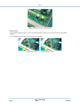
Figure 38: Installing SATA SSD and connecting SATA cables ............................. 35
Figure 39: Inserting mSATA module........................................................................... 36

Video Wall Mini User Manual
Video Wall Mini User ManualVideo Wall Mini User Manual
Video Wall Mini User Manual
x
Figure 40: Securing mSATA module........................................................................... 36
Figure 41: Inserting 3G/3.5G SIM card........................................................................ 37
Figure 42: Inserting 3G/3.5G module ......................................................................... 38
Figure 43: Securing 3G/3.5G module ......................................................................... 39
Figure 44: Installing 3G/3.5G antenna ........................................................................ 40
Figure 45: Installing WLAN USB module................................................................... 41
Figure 46: Installing WLAN antenna ........................................................................... 42
Figure 47: Connecting WLAN board to board cable ............................................. 43
Figure 48: Illustration of the Main menu screen....................................................... 46
Figure 49: Illustration of the Advanced Settings screen......................................... 48
Figure 50: Illustration of the ACPI Settings screen .................................................. 49
Figure 51: Illustration of the S5 RTC Wake Settings screen................................... 50
Figure 52: Illustration of CPU Configuration screen ................................................ 51
Figure 53: Illustration of SATA Configuration screen ............................................. 52
Figure 54: Illustration of USB Configuration.............................................................. 53
Figure 55: Illustration of F71869 Super IO Configuration screen......................... 55
Figure 56: Illustration of PC Health Status screen ................................................... 56
Figure 57: Illustration of Clock Generator Configuration screen ......................... 57
Figure 58: Illustration of Chipset Settings screen..................................................... 58
Figure 59: Illustration of DRAM Configuration screen ............................................ 59
Figure 60: Illustration of Video Configuration screen ............................................. 61
Figure 61: Illustration of PMU_ACPI Configuration screen .................................... 63
Figure 62: Illustration of Other Control screen........................................................ 64
Figure 63: Illustration of HDAC Configuration screen............................................ 65
Figure 64: Illustration of Others Configuration screen ........................................... 66
Figure 65: Illustration of Boot Settings screen.......................................................... 68
Figure 66: Illustration of Security Settings screen.................................................... 70
Figure 67: Illustration of Save & Exit screen.............................................................. 71
Figure 68: Front side setup diagram............................................................................ 76
Figure 69: Rear side setup diagram ............................................................................. 77

Video Wall Mini User Manual
Video Wall Mini User ManualVideo Wall Mini User Manual
Video Wall Mini User Manual
xi
Lists of Tables
Table 1: DC-In jack pinout ............................................................................................ 11
Table 2: HDMI
®
port pinout ......................................................................................... 12
Table 3: RJ-45 LAN port pinout................................................................................... 14
Table 4: RJ-45 LAN port color definition .................................................................. 14
Table 5: USB 3.0 port pinout........................................................................................ 15
Table 6: DIO connector pinout ................................................................................... 16
Table 7: USB 2.0 port pinout........................................................................................ 17
Table 8: COM connector pinout ................................................................................. 18
Table 9: LPC connector pinout .................................................................................... 19
Table 10: VGA pin header pinout ............................................................................... 20
Table 11: SPI pin header pinout .................................................................................. 21
Table 12: System temperature sensor pin header pinout...................................... 22
Table 13: System reset jumper settings ..................................................................... 24
Table 14: Reset CMOS RAM jumper settings ........................................................... 25
Table 15: SPI address select jumper settings ........................................................... 26
Table 16: Recovery BIOS jumper settings ................................................................. 27
Table 17: VDD/VSUSVDD mode select jumper settings ....................................... 28

Video Wall Mini User Manual
Video Wall Mini User ManualVideo Wall Mini User Manual
Video Wall Mini User Manual
1
1.
1.1.
1. Product Overview
Product OverviewProduct Overview
Product Overview
The Video Wall Mini is a rugged and completely fanless embedded system
designed with 4-display (HDMI) support via discrete S3 5400E graphics
processor onboard. Its system is based on the EITX-2003 mainboard powered
by 1.0+ GHz VIA QuadCore processor which is superb in multi-tasking
performance, high power computing operation with lower power
consumption.
The Video Wall Mini system supports dual-sided multiple I/O connectors such
as high definition audio jacks, USB ports, Gigabit Ethernet LAN port,
configurable COM connector and DIO connector. The Video Wall Mini system
offers a 2.5” SATA SSD bay and an optional WLAN USB (WiFi) connectivity
which can be supported through one on-board USB pin header. In addition, it
supports mini PCIe card slots for mSATA storage and 3G/3.5G connectivity
with SIM card slot.
The Video Wall Mini’s system chassis is a robust aluminum (top and bottom
cover) alloy and it is designed to support VESA-mounting for quick installation
and easy maintenance.
These combined features make the Video Wall Mini perfect for various digital
signage, video-wall, gaming, industrial and embedded applications.
1.1. Key Features
1.1.1. Powered by VIA
®
QuadCore Processor
The Video Wall Mini system is powered by VIA
®
QuadCore 1.0+ GHz
processor. The VIA
®
QuadCore processor has combined four 64-bit “Isaiah”
cores on two dies offering enhanced multi-tasking and superb multimedia
performance on a low power budget.
1.1.2. Fanless and Rugged Chassis
The Video Wall Mini features fanless operation in a ruggedized aluminum
chassis that does double duty as a thermal solution and designed to ensure
maximum reliability.

Video Wall Mini User Manual
Video Wall Mini User ManualVideo Wall Mini User Manual
Video Wall Mini User Manual
2
1.1.3. Multiple Display Support
The Video Wall Mini system comes with discrete S3 5400E graphics processor
that gives the ability to support four HDMI displays. Each display has a
maximum high definition resolution of 1920 x 1080p.
1.1.4. Optimize Integration with Multiple I/O Access
Front and right side I/O access enables the Video Wall Mini system to easily
access to peripherals, support various applications, easy integration, quick
setup and easy maintenance.
1.1.5. Storage Expansion
In addition to 2.5-inch SATA SSD supports, the onboard mini PCIe card slot
enables the Video Wall Mini to have a flexible storage mSATA module.
1.1.6. Wide Range of Operating Temperatures
The Video Wall Mini carries a qualified thermal performance design which
allows a wide range of operating temperatures from 0°C ~ 45°C, suitable for
critical applications.
1.1.7. Shock Resistant
The Video Wall Mini is shock resistant to 50G for maximum reliability.
1.1.8. Networking Support
The Video Wall Mini is equipped with RJ-45 port that supports high speed
Gigabit Ethernet. It also has wireless networking option that gives the system a
freedom of WiFi (WLAN) access and 3G/3.5G network connectivity through
mini PCIe card slot and USB pin header respectively.
1.1.9. Embedded OS ready
The Video Wall Mini is 100% compatible with Microsoft Windows 7, Microsoft
Windows Embedded Standard 7 with MagicView

Video Wall Mini User Manual
Video Wall Mini User ManualVideo Wall Mini User Manual
Video Wall Mini User Manual
3
1.2. Product Specifications
Processor
ProcessorProcessor
Processor Core Logic System
Core Logic System Core Logic System
Core Logic System
CPU
CPUCPU
CPU
VIA QuadCore U4650E 1.0+ GHz processor
800 MHz Front Side Bus
4 MB L2 Cache memory
NanoBGA2 package
Chipset
ChipsetChipset
Chipset
VIA VX11H Media System Processor
33 mm x 33 mm FCBGA
System Memory
System MemorySystem Memory
System Memory
One SODIMM slot supporting DDR3 1066/1333 MHz SDRAM
Supports up to 8 GB memory size
BIOS
BIOSBIOS
BIOS
AMI BIOS
32 Mbit EFI SPI flash memory
System Pow
System PowSystem Pow
System Power Management
er Managementer Management
er Management
Times Power On
ACPI 3.0 compliant
Graphics
GraphicsGraphics
Graphics
Controller
ControllerController
Controller
Integrated VIA Chrome™ 645/640 (DX11) graphics processor with 2D/3D video
acceleration with MPEG-2, VC-1 and H.264 video decoder
Display Memory
Display MemoryDisplay Memory
Display Memory
Optimized Shared Memory Architecture (UMA), supports 256MB to 1GB frame
buffer using system memory
HDMI
HDMIHDMI
HDMI
®
Interface
Interface Interface
Interface
Supports four onboard HDMI
®
ports via S3 5400E graphics
Video Wall
Video WallVideo Wall
Video Wall
Four onboard HDMI ports via S3 5400E graphics can support four display video
wall, dual view or other combination
Gigabit Ethernet
Gigabit EthernetGigabit Ethernet
Gigabit Ethernet
Controller
ControllerController
Controller
Onboard RTL8111G Gigabit Ethernet controller
Interface
InterfaceInterface
Interface
One RJ-45 LAN port
Supports Wake On LAN (WOL)
Supports Pre-boot Execution Environment (PXE)
High Definition Audio
High Definition AudioHigh Definition Audio
High Definition Audio
Controller
ControllerController
Controller
VIA VT2021 High Definition Audio Codec
Interface
InterfaceInterface
Interface
Supports two 3.5ø audio jacks as Line-Out and Line-In

Video Wall Mini User Manual
Video Wall Mini User ManualVideo Wall Mini User Manual
Video Wall Mini User Manual
4
USB
USBUSB
USB 2.0
2.0 2.0
2.0
Controller
ControllerController
Controller
Integrated USB 2.0 host controller built-in VX11 chipset on system board
Interface
InterfaceInterface
Interface
Two USB 2.0 ports
USB 3.0
USB 3.0USB 3.0
USB 3.0
Controller
ControllerController
Controller
VIA VL801 USB 3.0 host controller
Interface
InterfaceInterface
Interface
Supports two USB 3.0 ports
Serial Port
Serial PortSerial Port
Serial Port
Controller
ControllerController
Controller
Fintek F71869 LPC I/O controller
Interface
InterfaceInterface
Interface
Support two COM interface
One RS-232/RS-422/RS-485 COM connector (D-sub 9-pin)
One RS-232/RS-422/RS-485 COM connector through onboard pin header
Support 5V/12V Power selection pin headers onboard
Digital I/O
Digital I/ODigital I/O
Digital I/O
Interface
InterfaceInterface
Interface
Support 1 x DIO connector (D-sub 9-pin)
Storage
StorageStorage
Storage
Serial ATA
Serial ATASerial ATA
Serial ATA
Built-in one SSD hard drive bay for 2.5-inch SATA SSD
mSATA
mSATAmSATA
mSATA
Built-in one mini PCIe card slot for mSATA (support Gen2)
Expansion slot
Expansion slotExpansion slot
Expansion slot
M
MM
Mini
ini ini
ini PCIe
PCIe PCIe
PCIe card interface
card interfacecard interface
card interface
Support one mini PCIe card slot (PCIe + USB 2.0) for 3G/3.5G module
SIM card interface
SIM card interfaceSIM card interface
SIM card interface
Support one SIM card slot
Wireless LAN (
Wireless LAN (Wireless LAN (
Wireless LAN (o
oo
optional)
ptional)ptional)
ptional)
Controller
ControllerController
Controller
VIA VX11 Media System Processor
Interface
InterfaceInterface
Interface
Mini PCIe card interface of WiFi module
USB card interface of WiFi module
3G
3G3G
3G/
//
/3.5
3.53.5
3.5G
G G
G (
((
(o
oo
optional)
ptional)ptional)
ptional)
Controller
ControllerController
Controller
VIA VX11 Media System Processor
Interface
InterfaceInterface
Interface
Mini PCIe card interface of Ublox ZU200 3G/3.5 module, VNT9485 WiFi module
or AverMedia C353 capture card

Video Wall Mini User Manual
Video Wall Mini User ManualVideo Wall Mini User Manual
Video Wall Mini User Manual
5
Watchdog Timer
Watchdog TimerWatchdog Timer
Watchdog Timer
Output
OutputOutput
Output
System reset
Interval
IntervalInterval
Interval
Programmable 1 ~ 255 sec.
External I/O connectors
External I/O connectorsExternal I/O connectors
External I/O connectors
Front
Front Front
Front panel
panel panel
panel I/O
I/OI/O
I/O
One Power On/Off Button
One 4-hole DC-In jack power input
One green color LED indicator for Power On status
One red color LED indicator for SATA SSD activity
Four HDMI
®
ports
Two USB 3.0 ports
Two 3.5
ø
audio jacks (Line-Out and Line-In)
One RJ-45 LAN port (Gigabit Ethernet)
R
RR
Right side panel
ight side panelight side panel
ight side panel I/O
I/O I/O
I/O
One blue color LED for 3G/3.5G status
One blue color LED for WiFi (WLAN) status
One Digital I/O (D-sub 9-pin) connector (support 8-bit GPIO)
Two USB 2.0 ports
One COM (D-sub 9-pin) connector (support RS-232/RS-422/RS-485)
Two antenna holes (for WLAN antenna and 3G/3.5 antenna)
Onboard I/O
Onboard I/O Onboard I/O
Onboard I/O connectors
connectorsconnectors
connectors,
,,
, pin headers
pin headers pin headers
pin headers and jumpers
and jumpers and jumpers
and jumpers
One SATA II connector
One SATA II power connector
One LPC pin header (for debugging)
One CMOS battery connector
One System temperature sensor pin header
One Buzzer onboard speaker
One SPI bus pin header
One SPI address select jumper
One System reset jumper
One Reset/Clear CMOS RAM jumper
One VDD/VSUSVDD manual/auto mode select jumper
One Recovery BIOS function jumper
Power Supply
Power SupplyPower Supply
Power Supply
Power Input Connector
Power Input ConnectorPower Input Connector
Power Input Connector
One 4-hole DC-In jack
Power Consumpti
Power ConsumptiPower Consumpti
Power Consumption
onon
on
Typical 43.42W, Maximum 48.83W
Input Voltage
Input VoltageInput Voltage
Input Voltage
Built-in system DC-to-DC converter
DC 12V Power Input

Video Wall Mini User Manual
Video Wall Mini User ManualVideo Wall Mini User Manual
Video Wall Mini User Manual
6
Mechanical
MechanicalMechanical
Mechanical
Characteristics
CharacteristicsCharacteristics
Characteristics
Construction
ConstructionConstruction
Construction
Aluminum chassis housing with metal I/O plates
Mo
MoMo
Mounting
untingunting
unting
VESA mount
System d
System dSystem d
System dimension (
imension (imension (
imension (Length
LengthLength
Length x
x x
x Width
WidthWidth
Width x
x x
x Height
HeightHeight
Height)
))
)
255 mm x 250 mm x 46 mm
Weight
WeightWeight
Weight
3.7 Kg. (net weight)
Environmental Specification
Environmental SpecificationEnvironmental Specification
Environmental Specification
Operating Temperature
Operating TemperatureOperating Temperature
Operating Temperature
0°C ~ 45°C (with 2.5” SATA SSD)
0°C ~ 50°C (with mSATA)
Operating Humidity
Operating HumidityOperating Humidity
Operating Humidity
0% ~ 90%, relative humidity, non-condensing
Storage
StorageStorage
Storage Temperature
Temperature Temperature
Temperature
10°C ~ 60°C @ 90%, non-condensing
Vibration Loading during operation
Vibration Loading during operationVibration Loading during operation
Vibration Loading during operation (with
(with (with
(with 2.5”
2.5” 2.5”
2.5” SATA
SATA SATA
SATA SSD
SSDSSD
SSD)
))
)
5Grms, IEC 60068-2-64, random, 5~500Hz, 1hr/axis
Shock during operation (with
Shock during operation (with Shock during operation (with
Shock during operation (with 2.5”
2.5” 2.5”
2.5” SATA
SATA SATA
SATA SSD
SSDSSD
SSD)
))
)
50G, IEC 60068-2-27, half size, 11ms duration
Certification Requirements
Certification RequirementsCertification Requirements
Certification Requirements
EMC Approved
EMC ApprovedEMC Approved
EMC Approved
CE FCC, Class B, CCC
Software Compatibility
Software Compatibility Software Compatibility
Software Compatibility
Operating System
Operating SystemOperating System
Operating System
Microsoft Windows 7
Microsoft Windows Embedded Standard 7 with MagicView
Reminder:
Reminder:Reminder:
Reminder:
Use HDMI extender if the HDMI cable is over 10 meters (32.8 feet) long to overcome transmission
problem.
N
NN
Note:
ote:ote:
ote:
As the operating temperature provided in the specifications is a result of the test performed in VIA’s
chamber, a number of variables can influence this result. Please note that the working temperature may
vary depending on the actual situation and environment. It is highly suggested to execute a solid
testing and take all the variables into consideration when building the system. Please ensure that the
system runs well under the operating temperature in terms of application.

Video Wall Mini User Manual
Video Wall Mini User ManualVideo Wall Mini User Manual
Video Wall Mini User Manual
7
1.3. Panel Layout
Figu
FiguFigu
Figure
re re
re 1
11
1: Front side layout label
: Front side layout label: Front side layout label
: Front side layout label
Figure
Figure Figure
Figure 2
22
2: Right side layout label
: Right side layout label: Right side layout label
: Right side layout label
Figure
Figure Figure
Figure 3
33
3: Rear side layout label
: Rear side layout label: Rear side layout label
: Rear side layout label

Video Wall Mini User Manual
Video Wall Mini User ManualVideo Wall Mini User Manual
Video Wall Mini User Manual
8
Figure
Figure Figure
Figure 4
44
4: Bottom side layout label
: Bottom side layout label: Bottom side layout label
: Bottom side layout label
/