Page is loading ...

RedBot Assembly Guide a learn.sparkfun.com
tutorial
Available online at: http://sfe.io/t174
Contents
Introduction
**Wheel Encoder Screws**
Motors
Ball Caster
**RedBot Wheel Encoder**
RedBot Line Followers
Wheels
Standoffs
Battery Holder
RedBot MainBoard Standoffs
Jumper Wires
**RedBot Mechanical Bumpers**
**Adding the Bumpers**
Top Chassis
RedBot Mainboard
RedBot Accelerometer
**RedBot Buzzer**
RedBot Mainboard Hook-up
Batteries
Resources and Going Further
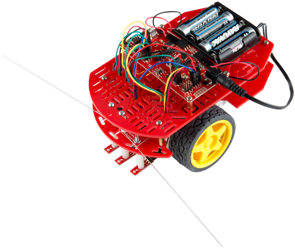
Introduction
The RedBot is robotic development platform capable of teaching basic robotics and sensor
integration! Based on the SparkFun RedBoard and programmable in the Arduino environment, the
RedBot has all the I/O you need to make a small robot in no time at all.
Page 1 of 46

Materials
This tutorial will cover how to install all the parts you received with your RedBot Kit, PLUS it will go
over how to install a few extra parts NOT included with the kit. These parts include:
RedBot Wheel Encoder
RedBot Buzzer
RedBot Mechanical Bumper
Again, you do not need these parts to assemble your RedBot, but they will be present throughout
this guide. Please ignore any instances of said extra sensors should you not need to assemble
them. Sections pertaining strictly to these extra parts will be marked with asterisks.
If you are installing one or all of these extras, you may also want to get a few more jumper wires.
Along with everything listed above, you will also need 4x AA batteries to power your RedBot.
Suggested Tools
Needle Nose Pliers
Screwdriver Set
Page 2 of 46

Suggested Reading
Before you go any further, you should probably make certain that you're familiar with the RedBot:
Getting Started with the RedBot
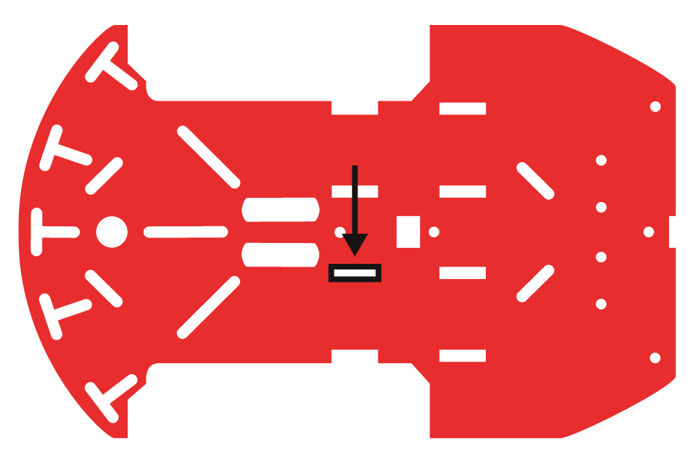
**Wheel Encoder Screws**
We will be placing screws that will later hold the RedBot Sensor - Wheel Encoder to the bottom
chassis.
**If you do not have a RedBot Sensor - Wheel Encoder, you will want to skip this section and move
on to the Motors section on this Assembly Guide. **
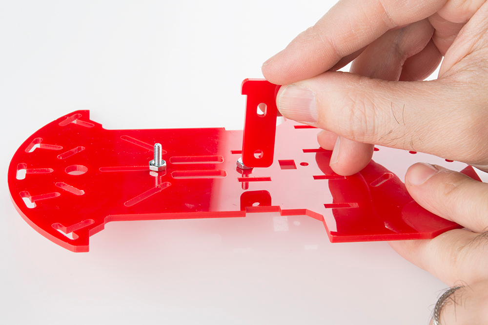
Locate the following:
1x Bottom Chassis Piece
2x 4-40 3/8" Phillips Screws
2x 4-40 Hex Nuts
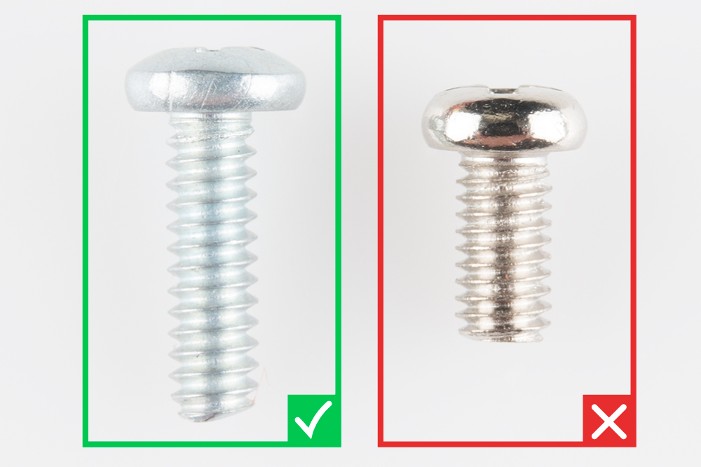
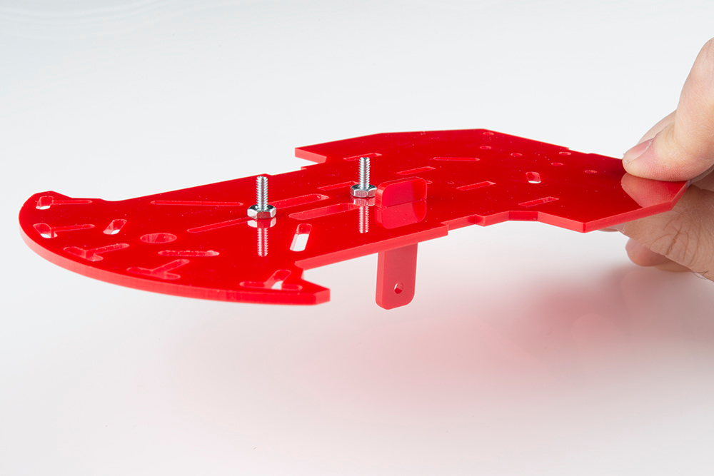
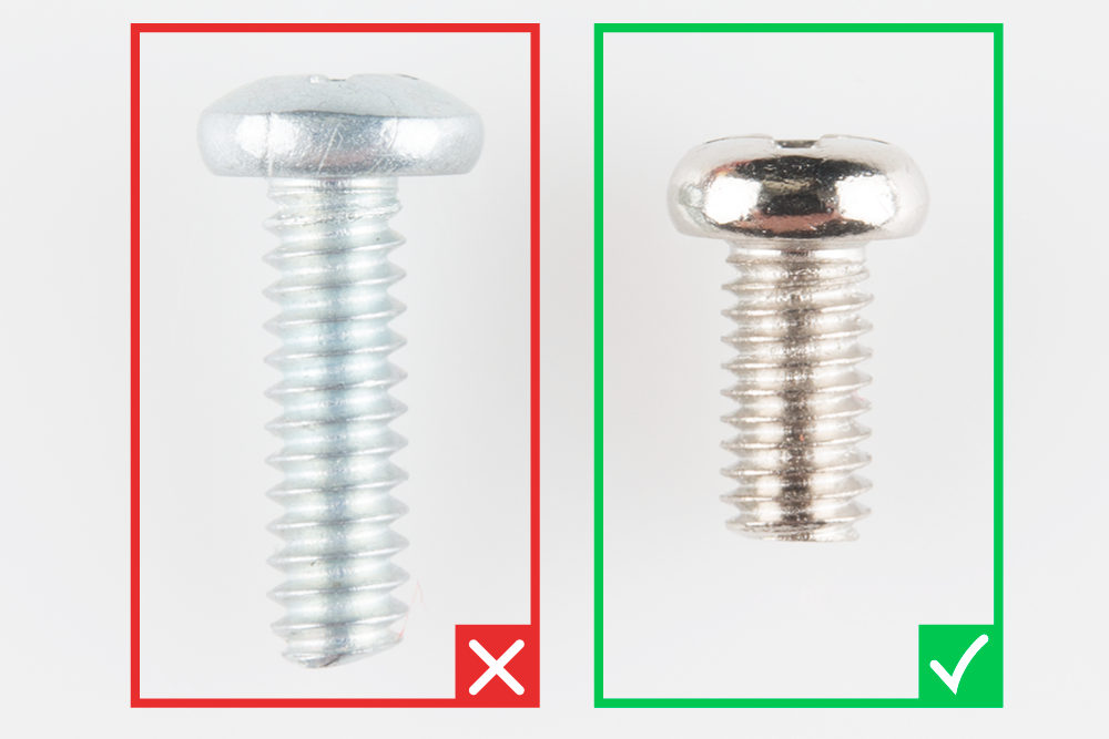
There are different types of screws in this kit. Make sure you use the 4-40 screws and nuts for the
RedBot Wheel Encoder. The 4-40 screws and nuts are packaged with the RedBot Sensor - Wheel
Encoder.
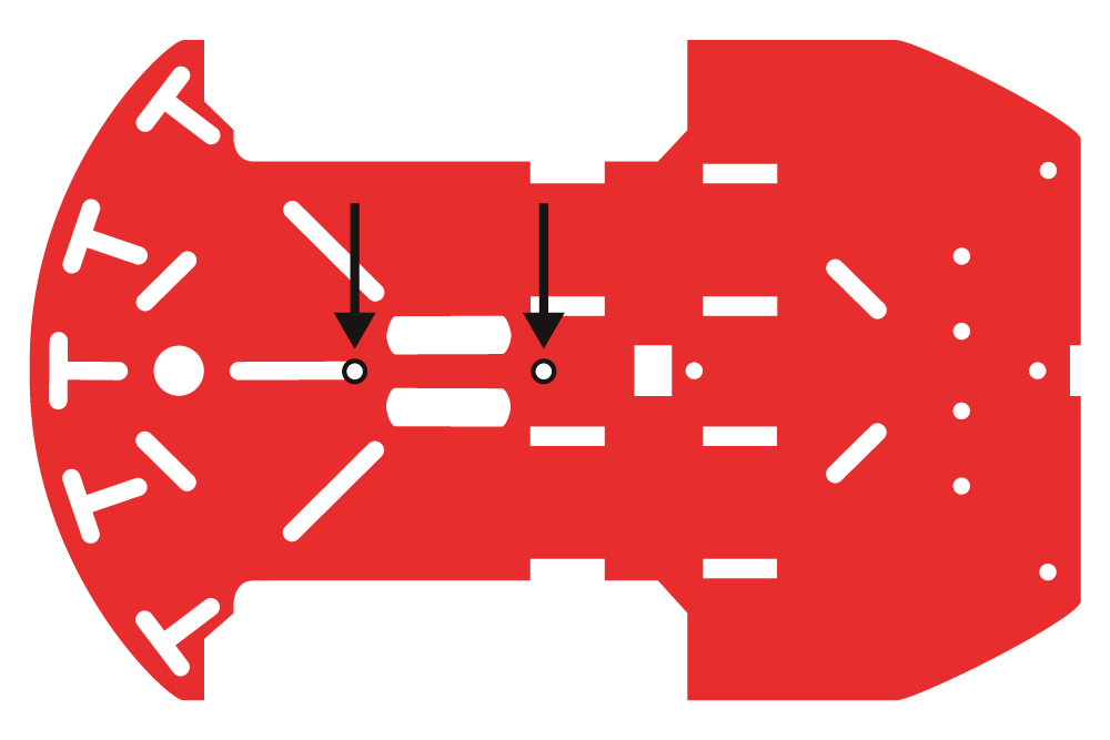
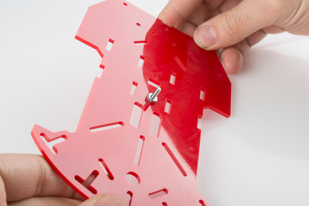
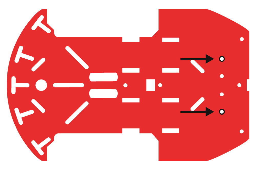
Locate the two positions on the bottom chassis piece where the 4-40 screws will go. In this step, it
doesn't matter what side you use, since both sides of the chassis are indential.
Page 3 of 46


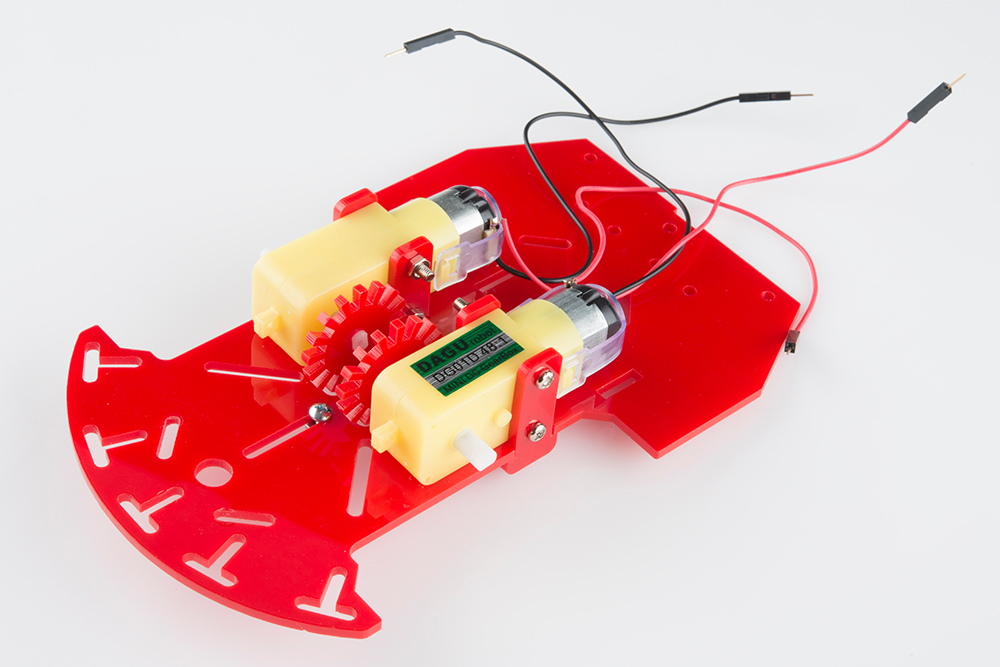
In this section, you will be placing the two motors on the bottom side of the bottom chassis piece. If
you are using the RedBot Sensor - Wheel Encoder, please play close attention to what chassis
side you are placing the motors on.
Locate the following:
1x Bottom Chassis Piece
4x Motor Holders
2x Motors
4x M3*30 Screws
4x M3 Nuts
2x Encoder Wheels
Locate the correct location on the bottom chassis piece.
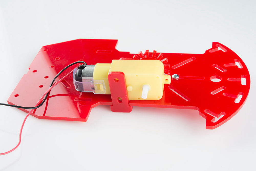
Place one of the motor holders through the right opening in the chassis. If you are using the RedBot
Sensor - Wheel Encoder, make sure you are on the top side of the chassis piece. The top side will
have the 4-40 hex nuts showing.
Page 6 of 46


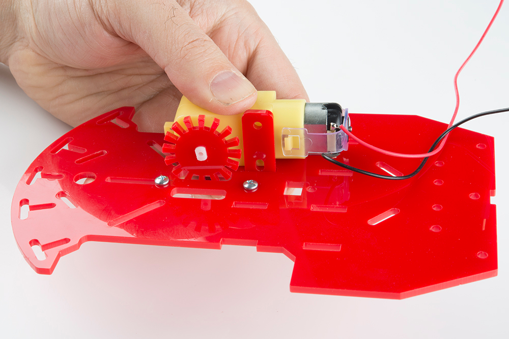
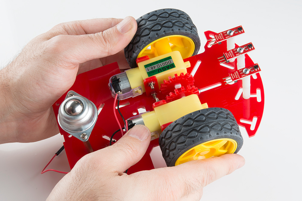
Place the first motor on the bottom side of the chassis piece. Line up the two motor holes with the
two motor holder holes. Make sure that the red wire is on top and away from the chassis piece.
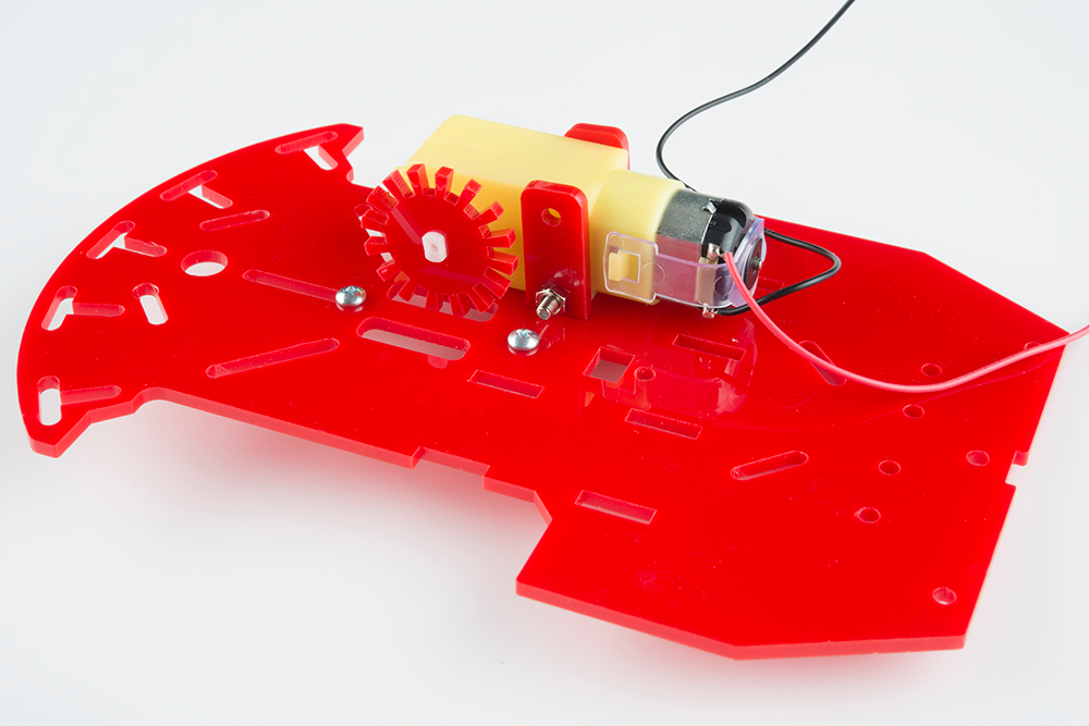
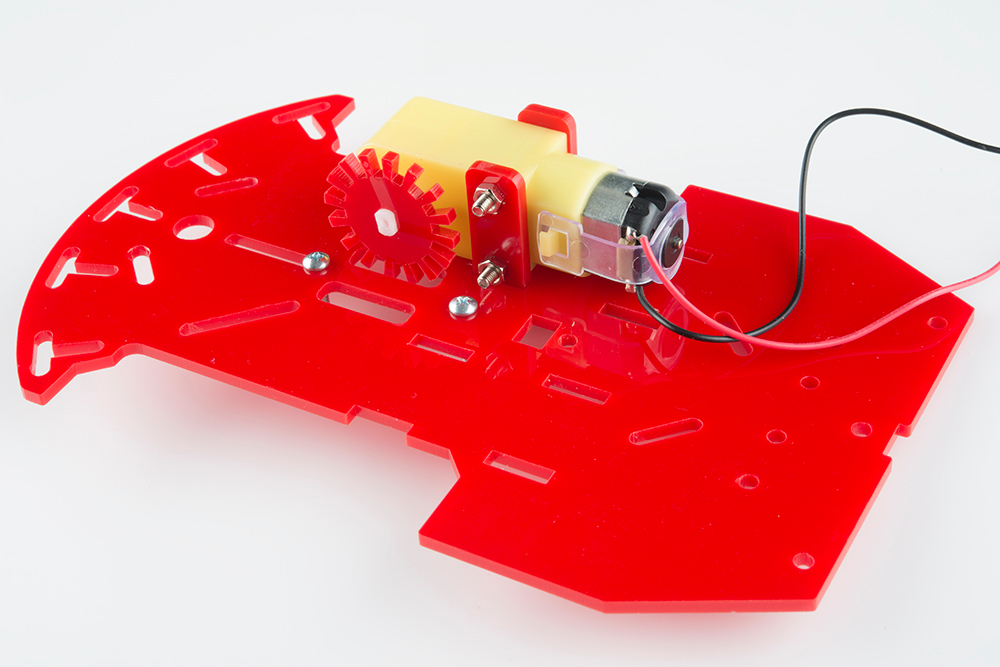
If you are adding wheel encoders to your RedBot, do so now. If not, ignore the encoder (the red
gear looking piece) in the following pictures. Make sure the encoder wheel fits in the chassis
opening without touching the opening's sides.
Page 8 of 46


In this section, you will be adding the ball caster to the bottom side of your bottom chassis piece.
Locate the following:
4x M3*6 Screws
2x L25 Metal Standoffs
1x Ball Caster
There are different types of screws in this kit. Make sure you use the M3*6 screws for this section.
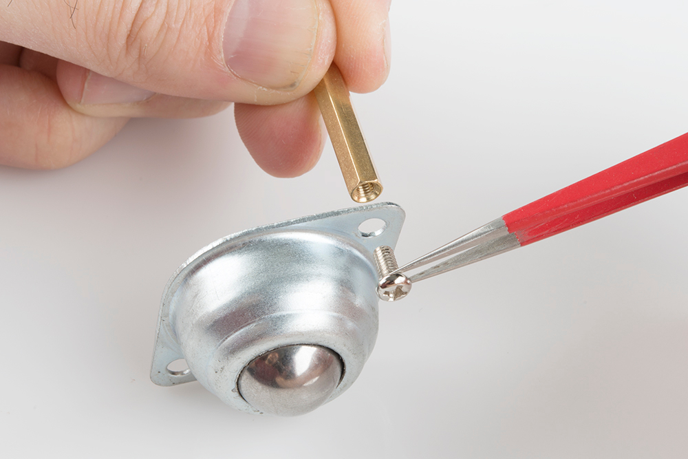
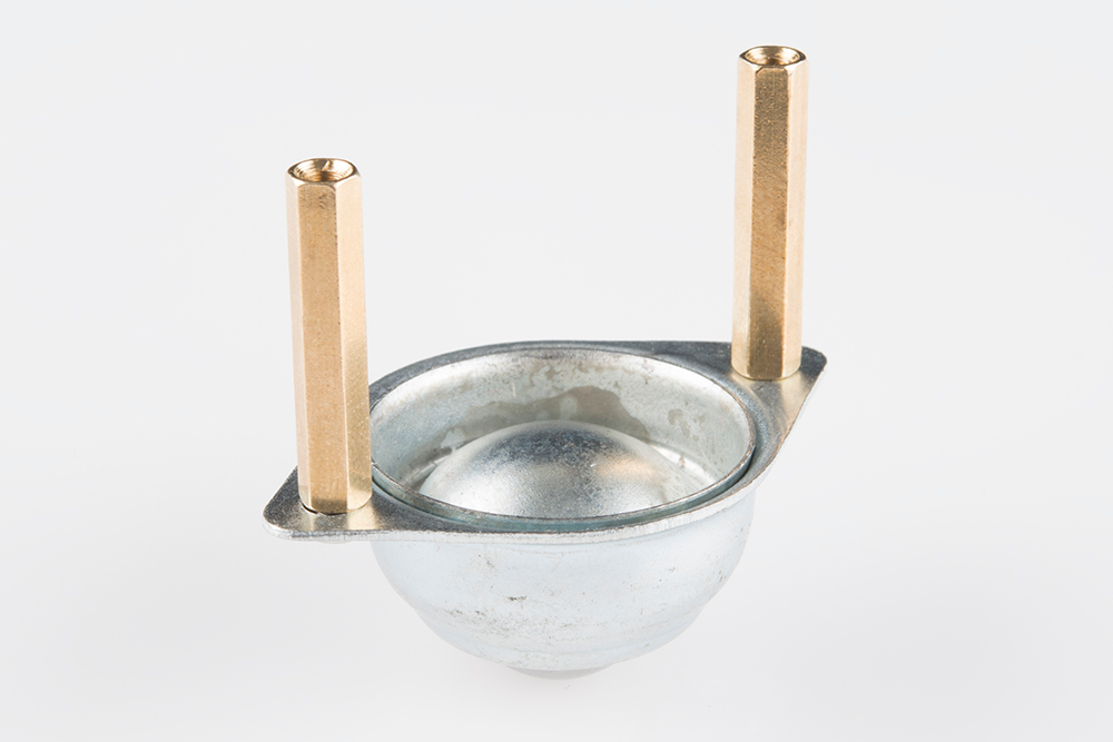
Place a M3*6 screw through one of the ball caster's holes. The screw's head should be on the
same side as the ball caster's metal ball. Then screw in one of the L25 standoffs to the ball caster.
Please note: the L25 metal standoffs will be longer then the L10 metal standoffs.
Page 12 of 46


**If you are not using the RedBot Sensor - Wheel Encoder, you may skip to the next section. **
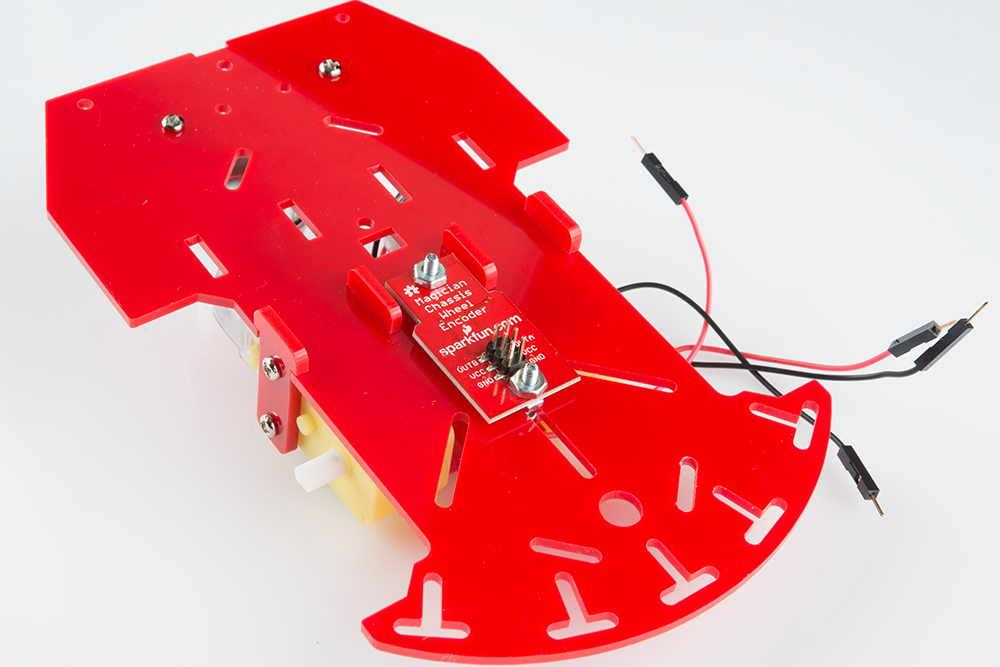
If you are using the RedBot Sensor - Wheel Encoder, in this section you will be tightening down the
RedBot Sensor - Wheel Encoder to the bottom chassis piece.
Locate the following:
1x RedBot Sensor - Wheel Encoder
2x 4-40 Hex Nuts
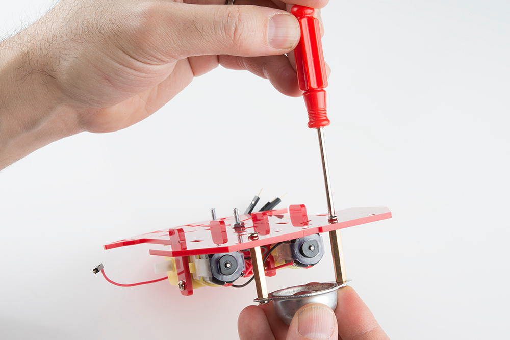
With the six pin male header side on the RedBot Sensor - Wheel Encoder facing upwards, place
down the encoder on the top side of the bottom chassis piece. Pay close attention that the six pin
male header side is also closest to the front side of the chassis. Using two 4-40 hex nuts, tighten
down the RedBot Sensor - Wheel Encoder on the top side of the bottom chassis piece in the same
location in the earlier "Wheel Encoder Screws" section in this assembly guide.
RedBot Line Followers
In this section, you will be putting standoffs on the RedBot Sensor - Line Followers. Then you will
add the sensors on your chassis.
Locate the following:
3x Line Followers
3x 4-40 1" Phillips Screw
3x 4-40 1/4" Phillips Screw
Page 15 of 46

6x 4-40 Nylon Standoffs
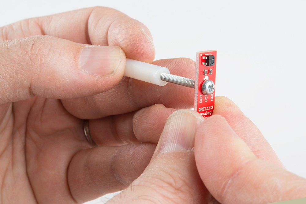
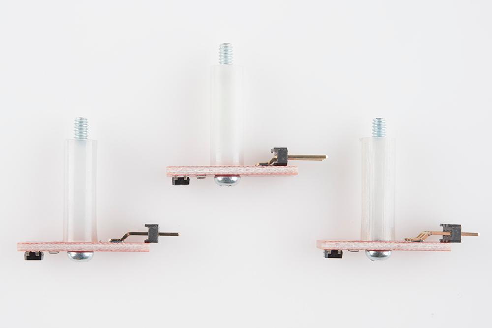
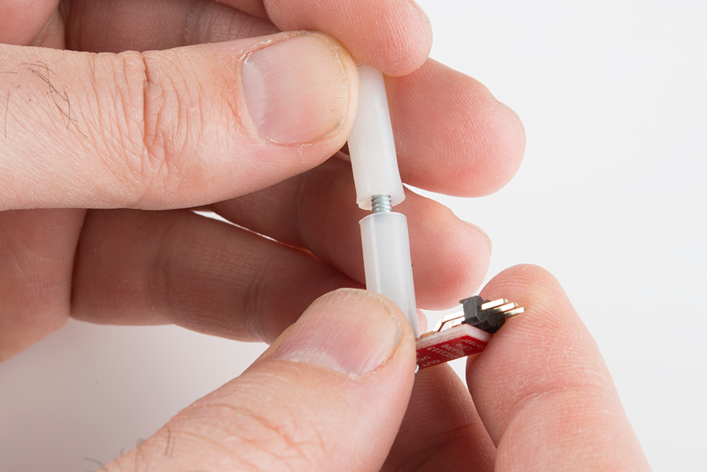
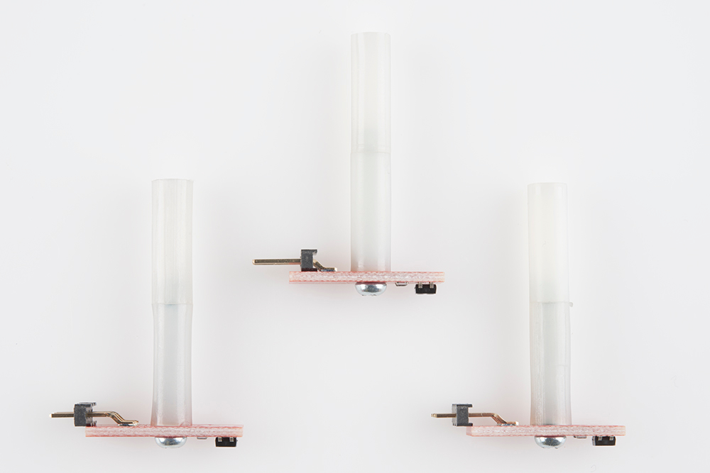
Screw a 4-40 1" Phillips screw to the plastic standoff through one of the RedBot Sensor - Line
Followers. Make sure to tighten the standoff on the line follower's header side. The top of the screw
should be on the same side as the RedBot Sensor - Line Follower's sensor. Do this for the other
two RedBot Sensor - Line Followers.
You should see part of the 4-40 1" Phillips screw sticking out.
Page 16 of 46


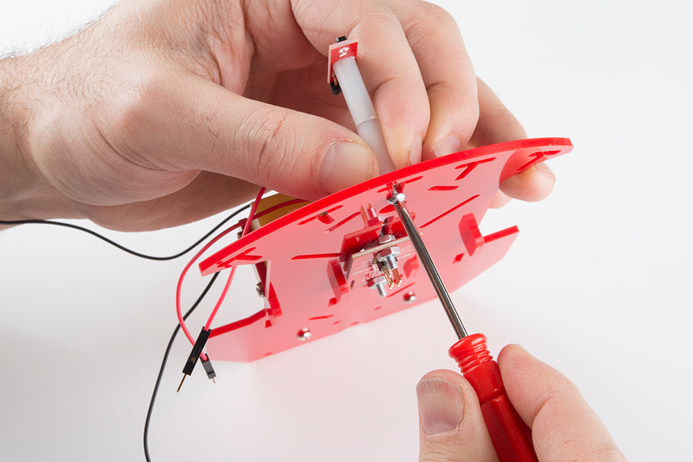
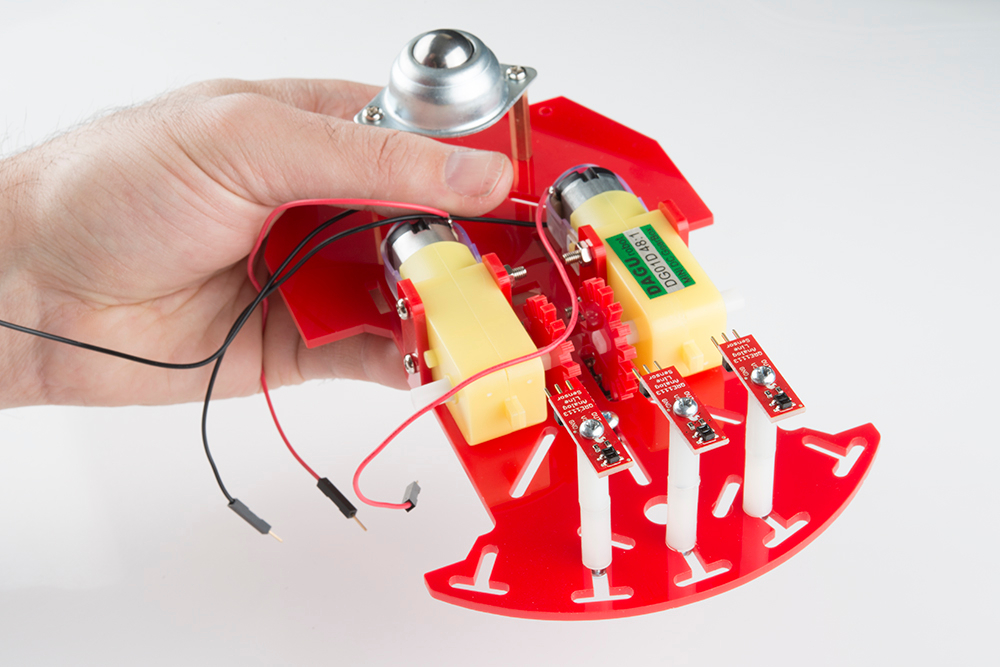
Locate three spots on the chassis where you will be adding the RedBot Sensor - Line Followers.
Place a 4-40 1/4" Phillips screw through the top side of the chassis piece. Tighten down the
standoff with a RedBot Sensor - Line Follower into bottom chassis piece. The RedBot Sensor - Line
Follower should be on the bottom side of the chassis piece. The headers on the RedBot Sensor -
Page 18 of 46


/