Page is loading ...

READ AND SAVE THESE INSTRUCTIONS
DRI-STEEM
GTS
®
and GTS
®
-DI
EUROPEAN MODEL
GAS-TO-STEAM HUMIDIFIERS
Installation, Operation
and
Maintenance Manual
This manual must be left with the owner and should be accessible for reference.
WARNING: If the information in this manual
is not followed exactly, a fire or explosion
may result causing property damage,
personal injury, or loss of life.
• Do not store or use petrol (gasoline) or other flammable
vapors and liquids in the vicinity of this or any other appliance.
WHAT TO DO IF YOU SMELL GAS
• Do not try to light any appliance.
• Do not touch any electrical switch; do not use any
phone in your building.
• Immediately call your gas supplier from an off-site
phone. Follow the gas supplier's instructions.
• If you cannot reach your gas supplier, call the fire
brigade.
• Installation and service must be performed by a qualified
installer, service agency, or the gas supplier.

TO THE PURCHASER AND THE INSTALLER
Thank you for purchasing DRI-STEEM Model GTS
®
equipment. We
have designed and built this equipment to give you total satisfaction
and many years of trouble-free service. Proper installation and
operating practices will assure you of achieving that objective. We
therefore urge you to become familiar with the contents of this
manual.
This equipment has been tested by Canadian Standards Association
International to the Low Voltage, Gas Appliance, and EMC directives
and has been certified by AFNOR for use in all EU countries.
DRI-STEEM Humidifier Company
AUTHORIZED COUNTRIES OF DESTINATION
The GTS and GTS-DI humidifiers bearing the CE mark are
authorized for use in the European countries listed below.
Austria AT Greece GR
Belgium BE Ireland IE
Switzerland CH Iceland IS
Germany DE Italy IT
Denmark DK Luxembourg LU
Spain ES Netherlands NL
Finland FI Norway NO
France FR Portugal PT
United Kingdom GB Sweden SE
APPLIANCE CATEGORY
In relation to the country of destination, this humidifier is classified
under one of the following boiler categories: category I
2H
, I
2L
, I
2E
, I
2E+
,
I
2LL
, I
2ES
, I
2Fi
, or I
2ER
.
See the unit data plate for the specific category of your appliance.
FOREWORD
2

GTS Program Code Nomenclature ..................................... 4
Models GTS and GTS-DI ...................................................... 5
Safety Precautions ............................................................... 6
Specifications and Capacities ............................................. 7
Dimensions ........................................................................... 8
Installation
Precautions ................................................................ 9
Required Clearance ................................................... 9
Locating the Humidifier ............................................... 10
Supply Water and Drain Overflow Connections .......... 10
Makeup Water Piping and Material............................. 11
Drain Piping and Material ........................................... 11
Gas Piping.................................................................. 12
Gas Leak Testing ....................................................... 13
Electrical .................................................................... 13
Combustion and Ventilation Air .................................. 14
Flue Venting Guidelines (Flue Connection) ................ 15
Mounting the Humidifier
Standard .................................................................... 16
Indoor Cover .............................................................. 16
Steam Supply Connection Methods ................................... 17
Condensate Return Piping .................................................. 18
RAPID-SORB
®
Assembly and Installation
Horizontal Duct Installation ......................................... 19
Vertical Duct Installation ............................................. 20
ULTRA-SORB
®
Installation .................................................. 20
AREA-TYPE Application ...................................................... 21
Start-up and Operation ........................................................ 22
Maintenance
GTS (Standard Model Only) ....................................... 23
GTS-DI Model Only .................................................... 23
Both GTS and GTS-DI ............................................... 24
Replacement Parts ............................................................... 25
Wiring Diagrams ................................................................... 29
Caution Labels ..................................................................... 33
Maintenance Service Record ............................................... 34
Two-Year Limited Warranty ................................................. 38
TABLE OF CONTENTS
3

GTS PROGRAM CODE NOMENCLATURE
A 14-digit VAPOR-LOGIC
®
3
program code appears
on the front of the control cabinet and on the
wiring diagram inside the control cabinet. The
program code specifies the parameters of the
VAPOR-LOGIC
3
microprocessor, which controls
your humidification system. An explanation of the
program code is detailed below.
VAPOR-LOGIC
3 program code
A. VAPOR-LOGIC
3
system type:
G = GTS
®
S = STS
®
L = LTS
®
V = VAPORSTREAM
®
M = HUMIDI-TECH
®
C = CRUV
®
U = ULTRA-FOG
®
N = Steam Injection
B. VAPOR-LOGIC
3
board classification:
1 = One-tank system
2 = Two-tank system
3 = Three-tank system
4 = Four-tank system
5 = Five-tank system
6 = Six-tank system
C. Digital display/keypad features:
1 = Single keypad
D. Type of outputs:
0 = Steam valve/100% SSR
1 = One heat stage
2 = Two heat stages
3 = Three heat stages
4 = Four heat stages
E. System capacity:
##### = Output capacity code
F. Type of water level control:
D = DI w/ manual drain
E = DI w/ end of season drain
M = Standard w/ manual drain
A = Standard w/ autodrain
G. Operating mode:
1 = Single staged
2 = Externally staged
3 = not used
4 = not used
5 = not used
6 = GTS
7 = TP
8 = SSR
9 = Steam valve
H. VAV options:
V = Option present
O = Option not selected
S = SDU option
I. Temperature compensation options:
T = Option present
O = Option not selected
J. Type of humidity sensing device:
N = None, for on/off
C = 0-135 ohm humidistat
D = 6-9 VDC humidistat
H = 0-10 VDC humidistat
E = 4-20 mA humidistat
X = 4-20 mA transmitter
Q = Dew point transmitter
S = Special
4

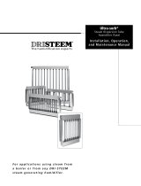
GTS
®
AND GTS-DI HUMIDIFIERS
GTS Gas-to-Steam
Humidifier
The GTS is a gas-fired humidifier that
burns natural gas to generate steam
for humidification. The unit consists
of one or two burners, which are fired
into a heat exchanger. This heat
exchanger is, in turn, submerged in a
tank of water. When there is a call for
humidity, the burners fire and gener-
ate steam until the call for humidity
ends. The GTS is compatible with all
types of DRI-STEEM dispersion
devices, including RAPID-SORB
®
and ULTRA-SORB
®
.
The GTS humidifier is designed to be
used with all water types. The
standard GTS model supports
softened or unsoftened water and
uses a probe-type level control
system to sense water level. This
probe requires water conductivity of
100 mS/cm to function. Therefore, it
will not operate on water treated by
reverse osmosis or deionization.
The GTS-DI model is available for
use with deionized or reverse osmo-
sis water. This unit produces chemi-
cal-free steam and reliable, accurate
humidification control. It is virtually
maintenance-free, with no wasted
water, heat, or downtime. The DI unit
uses a float valve to control water
levels. The standard GTS model can
be converted to a GTS-DI model in
the field.
OM-1084
Drain Valve
Gas
Valve
Probes or Float
Fill Valve
Heat Exchanger
Evaporating Chamber
Cover
Blower
ULTRA-SORB
®
Cover Knob
Control Panel
Shroud
Flue Box
5

SAFETY PRECAUTIONS
WARNING:
Improper installation, adjustment, alteration, service,
maintenance, or use can cause carbon monoxide
poisoning, an explosion, fire, electrical shock, or other
conditions which may cause personal injury or property
damage. Consult a qualified installer, service agency,
local gas supplier, or your distributor or branch for
information or assistance. The qualified installer or
agency must use only factory authorized and listed kits
or accessories when modifying this product. A failure
to follow this warning can cause electrical shock, fire,
personal injury, or death.
• Inspect humidifier and accessories upon arrival for
damaged, missing, or improper parts. If there is a
problem, call DRI-STEEM.
• Application of this humidifier should have special
attention given to vent sizing and material, gas input
rate, and unit sizing. Improper installation or misappli-
cation of the humidifier can cause excessive servicing
or permanent component failure.
• When working on equipment, observe precautions in
this literature, tags, and labels attached to or shipped
with the unit and other safety precautions that may
apply. Wear safety glasses and work gloves. Have a
fire extinguisher available during start-up, adjustment
procedures, and service calls.
• Do not use this appliance if any part has been under
water. Immediately call a qualified service technician to
inspect the appliance and to replace any part of the
control system and any gas control which has been
under water.
• Do not lift humidifier by gas controls, gas manifold,
fire box, or control shroud.
• Should overheating occur, or the gas supply fail to
shut off, shut off the manual gas valve to the appliance
before shutting off the electrical supply.
• This equipment is for use with second family (G20,
G25) natural gases only.
• Conversion to another group or supply pressure
should be carried out by a competent person.
Conversion Instructions:
• No replacement parts are required for conversion.
* A flat screwdriver will be required to adjust the gas
valve throttle screw. A combustion analyzer and pres-
sure gauge will be required to ensure proper adjustment.
A gas meter must be installed on the incoming gas
supply to ensure proper input. Turning the throttle screw
counter-clockwise will increase the gas input, clockwise
decreases input. Use the gas meter and analyzer to
determine proper combustion at the stated input.
• Throttle screw seal shall be replaced upon completion
of adjustment.
• For appliances operating with a pressure couple, any
governor shall be made inoperative.
• Contact an authorized DRI-STEEM distributor to
receive the proper replacement data plate.
Electrical Warning Label:
Location: Control cover, shroud
Definition: Electrical shock hazard
6

SPECIFICATIONS AND CAPACITIES
Table 7-1: Specifications
Capacity Notes
• Approximately 402 kJ are required to raise the tem-
perature of one kg of water from 4°C to 100°C.
• An additional 2257 kJ are required to change one kg
of water to water vapor.
• Another factor to consider is condensation steam loss
from hoses and tubes. Use the following steam loss
guidelines:
- vapor hose: 0.22 kg/m/h
- insulated pipe: 0.07 kg/m/h
- dispersion tubes: 0.7 kg/m/h
• The maximum steam capacities listed may be as
much as 10% higher than the give values due to local
variations in the Wobbe index of G20 and G25 gases.
ledoM
rebmun
maetS
yticapac
ruohrep
gkni
)Wk(=P)Wk(=Q
maetS
teltuo
dednemmoceR
nieziseulf
mm/sehcni
)BssalC(
gnitar
epO
thgiew
gkni
gnippihS
thgiew
gkni
roodtuO
erusolcne
gnitarepo
gknithgiew
roodtuO
erusolcne
gnippihs
nithgiew
gk
lluF
daol
spma
001-STG
4302-042-0
PSB)"2(05ND
esoh05NDro
)"5(521ND5925910945839.2
002-STG
8684-095-0
PSB)"2(05ND
esoh05NDr
o
)"5(521ND5925910945839.2
003-STG
20127-088-0egnalf)"3(08ND)"7(081ND0145220060245.3
004-STG
63159-0711-0egnalf)"3(08ND)"7(0
81ND0145220060245.3
Operating Characteristics:
• Unit is capable of operating in ambient conditions of
5°C - 40°C.
• Unit is capable of operating in ambient conditions
between 30% RH and 95% RH (non-condensing).
•NO
x
class 5
Gas Supply Pressure: 20 mbar or 25 mbar, depending
on gas group. See data plate information.
PMS (all units): 7.0 bar
Electric Supply: 230V, 667W-2415W (see data plate)
Max Inlet Water Temperature: 90°C
Table 7-2: Volumetric flow rate by gas category and other characteristics
reifidimuH
ledom
yrogetacsagybetarwolfcirtemuloV
eulfegarevA
erutarepmet
muminiM
thguard
tnemeriuqer
wolfssaM
foetar
noitsubmoc
stcudorp
rabm02-02G-H2
rabm02-02G-E2
rabm02-02G-sE2
rabm52-52G-L2
rabm02-52G-LL2
rabm52-52G-iE2
rabm52/02-52G/02G+E2
rabm52/02-52G/02G-RE2
001STG
m13.2
3
h/m28.2
3
h/m28.2-13.2
3
h/C°121rabm520.0-s/g9.6
002STG
m26.4
3
h/m46.5
3
h/m46.5-26.4
3
h/C°361rabm520.0-s/g8.31
003STG
m29.6
3
h/m64.8
3
h/m64.8-29.6
3
h/C°191rabm520.0-s/g7.02
004STG
m26.7
3
h/m13.9
3
h/m13.9-26.7
3
h/C°812rabm520.0-s/g8.22
7

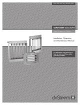
DIMENSIONS
Figure 8-1: Dimensions
Side View
A
K
H
R
S
B
Top View
L
J
Q
P
E
Front View
N
F
D
G
C
M
noitpircseD
001-STG
002-STG
)renrub-enO(
mm
003-STG
004-STG
)renrub-owT(
mm
AhtdiwdnatsroolF018018
BhtgnelllarevO031
15421
CrebmahcgnitaropavefothgieH038038
D
noitisopteltuomaetS
532503
E532532
FhtdiwllarevO536577
Gtenibaclortnocfothgie
H015015
HthgiehduorhS518518
J
noitisopeulF
512503
K031041
LretemaideulF)"5(521ND)"7(081ND
M)roolfmorfecnatsid(thgiehgeL04
3043
NhtdiwgeL074016
PevlavlliF5858
QtniopnoitcennoC5353
R
noitisopgulpnruteretasnednoC
536536
S585585
8

Cover 457 mm
Heat
exchanger
762 mm
Control
cabinet
914 mm
Burner
shroud
762 mm
OM-1081
INSTALLATION
Precautions
• Installation must conform to the requirements of the
authority having jurisdiction.
• Do not install in potentially explosive or flammable
atmospheres laden with grain dust, sawdust, or similar
airborne materials.
• Installation of humidifier in high humidity or salt water
atmospheres will cause accelerated corrosion, resulting
in a reduction of the normal life-span of the unit.
• To prevent premature heat exchanger failure, do not
locate ANY gas-fired unit in areas where chlorinated,
halogenated or acid vapors are present in the
atmosphere.
• Locate the humidifier in an area clear of combustible
materials, gasoline, and other flammable vapors and
liquids.
• With the exception of sealed combustion units, do
not locate units in tightly sealed rooms or small
compartments without provision for adequate
combustion air and venting. Room air combustion must
be supplied through a minimum of two permanent
openings in the wall, at least one near the bottom. The
openings should provide 6.50 cm
2
of free area per 300W
input rating of the unit, with a minimum of 650 cm
2
for
each opening. See table 14-1 and information on pages
14 and 15 for additional information.
• Remove all shipping brackets and materials before
operating the humidifier.
• Humidifier flue gases must be vented to the outside
atmosphere.
• Power supply disconnect switch must be in the off
position while making wiring connections to prevent
electrical shock and equipment damage. All units must
be wired in strict accordance with wiring diagram
furnished with this unit.
• Turn off all gas while installing the gas piping and
manual shut-off valve for the humidifier.
GTS clearance recommendations
Handling instructions:
• Keep unit upright during handling.
• Do not lift unit by control cabinet or shroud.
• Do not bend electrical conduit past 90°.
Required Clearance:
For recommended service and maintenance purposes
the following clearances should be maintained:
• Heat exchanger removal - front, 750 mm
• Burner shroud removal - front, 750 mm
• Control cabinet - right side, 915 mm
• Cover removal - top, 450 mm
• Distance from vent box to combustible
floor - 750 mm
• A minimum of 25 mm clearance is
recommended between hot surfaces and
combustible walls.
9

INSTALLATION
Locating the Humidifier
• Provide a level, solid foundation for the humidifier.
Locate the humidifier as near as possible to chimney or
outside wall so that the flue pipe from the humidifier is
short and direct. The location should also be such that
the gas ignition system components are protected from
water during humidifier operation and service.
• The humidifier should be installed in a location away
from drafts and properly protected. If installed in a
separate room, follow the instructions concerning
combustion and ventilation air.
• The humidifier should be located in an area where
leakage from the tank or its connections will not result
in damage to the adjacent structure or to lower floors of
the structure. When such locations cannot be avoided,
it is recommended that a suitable drain pan, adequately
drained, be installed under the humidifier. The pan must
not restrict combustion air flow.
• The humidifier must not be installed on carpeting,
tile, or other combustible material other than wood
flooring (indoor application only).
• Install humidifier so electrical components are
protected from water.
• The appliance must be kept free and clear of insulat-
ing materials when located in an insulated space.
Insulating material may be combustible. Inspection of
the appliance area must be performed when the appli-
ance is installed, or when insulation is added.
• Locate the humidifier in an area where operating
noise will not be objectionable.
• The VAPOR-LOGIC
®
3
keypad should be mounted in
an easily accessible location for the operator between
0.4 m and 1.6 m above the floor.
Important:
• Remove all shipping brackets and materials before
operating the humidifier.
• Humidifier flue gases must be vented to the outside
atmosphere.
• Power supply disconnect switch must be in the off
position while making connections to prevent electrical
shock and equipment damage. All units must be wired
in strict accordance with wiring diagram furnished with
this unit.
• Turn off all gas while installing the run-out and
manual shut-off valve for the humidifier.
Supply Water and Drain Overflow
Connections
IMPORTANT: The humidifier is shipped with the
automatic drain valve locked in the manual open
position. This position reduces the possibility of
damaging the valve seat from the heat of sweating the
drain connection during installation. After the drain
connection has been completed, the “manual open”
lever position must be reset to the auto position. Failure
to close the drain valve will not allow the tank to fill.
Regardless of the type of water used, the following
general instructions must be followed:
• Union connections must be made at the humidifier on
the cold water supply and drain/overflow lines.
• A shut-off valve should be provided in the supply
water line to isolate the humidifier from the water
system while servicing.
• If the water pressure is above 420 kPa and/or water
hammer would be objectionable, a pressure reducing
valve or shock arrester should be installed.
• A DN25 (1") opening is provided in the humidifier tank
to accommodate skim and/or overflow protection.
(Note: Follow local code requirements regarding size of
drain pipe.)
• Insulating unions or bushings must be used to make
connections between copper and other dissimilar metal
fittings, such as galvanized steel. These insulating
fittings are required to minimize electrolytic corrosion,
which results from the direct connection of dissimilar
metals in a water system.
• Before beginning ignition sequence of the humidifier
at a new installation, be sure the humidifier tank is full of
water and the water is free to flow into the tank.
10

INSTALLATION
Makeup Water Piping and Material
Minimum makeup water pressure must be 175 kPa.
When nonmetallic water piping is used, it must be rated
to withstand 100°C or greater temperature. If not, the
final three feet connected to the humidifier should be
metallic and should not be insulated.
As part of the fill valve assembly, the needle valve
restricts the rush of cold water entering the evaporating
chamber during the fill cycle. Adjusting the supply
water flow with the needle valve will reduce fill cycle
OM-737N
* Drain piping material must be suitable for 100°C water.
** Refer to local codes for drain pipe sizing and maximum temperature
requirements.
DI Water
noise from the collapsing steam head in the humidifier.
Adjusting the needle valve will also reduce the drop in
output during a fill cycle. Care must be taken to not
reduce the fill rate below the humidifier's capacity, as
this will cause a low-water shutdown.
Drain Piping and Material
If nonmetallic pipe or hose is used, it must be capable
of withstanding temperatures up to 100°C.
DN6 (¼") water supply line
175 kPa minimum
Steam outlet
SST manual
drain valve
Water skim/overflow outlet
Air gap
Open drain
**
Shroud
Float-operated low
water cutoff
Float-operated water
makeup valve
Flue connection
Drain piping
*
(by installer)
OM-736N
Standard Water
DN6 (¼") water supply line
175 kPa minimum
Steam outlet
Manual electric drain valve
Water skim/overflow outlet
Air gap
Open drain
**
Shroud
Three-probe level control
and low water cutoff
Solenoid water
makeup valve
Flue connection
Drain piping
* (by installer)
Redundant low water cutoff sensor
Condensate plug
11

INSTALLATION
Gas Piping Guidelines
CAUTION:
Gas pressure to humidifier controls must never
exceed 59 mbar. A DN6 (1/8") plugged tapping,
accessible for test gauge connection, must be
installed immediately upstream of the gas supply
connection to the appliance.
• After threading and reaming the ends, inspect piping
and remove loose dirt and chips.
• Support piping so that no strains are imposed on unit
or controls.
• Use two spanners when connecting piping to unit
controls.
• Provide a drip pocket before each unit and in the line
where low spots cannot be avoided.
• Supply to unit should be piped from top or side of gas
main to avoid trapping condensate.
• Piping subject to wide temperature variations should
be insulated.
• Pitch piping up toward unit at least 1.5mm per metre
of horizontal run.
• Compounds used on threaded joints of gas piping
must be resistant to the harmful action of liquefied
petroleum gases.
• Purge air before lighting unit by disconnecting piping
at gas control. In no case should line be purged into
heat exchanger.
• After installation, check field piping and humidifier gas
train for gas leaks.
• Do not use soap solution, or open flame on humidifier
gas train. A gas leak detector is recommended.
• Install a ground joint union and a manual shut-off
valve immediately upstream of the unit including a DN6
(1/8") plugged tapping accessible for test gauge connec-
tion. Pressure tappings for test gauges are located on
all gas valves.
• Allow at least 1.5 m of piping between any high
pressure regulator and unit pipe connection.
• Piping installation must be in accordance with local
codes. Do not use flexible connectors.
• Piping to units should conform with local and national
requirements for type and volume and gas handled, and
pressure drop allowed in the line. Refer to table 13-1,
and 13-2 to determine the volumetric flow rate for the
type of gas and size of unit to be installed. Using this
value and the length of pipe necessary, determine the
pipe diameter. Where several units are served by the
same main, the total capacity, gas flow (m
3
/h), and
length of main must be considered. Avoid pipe sizes
smaller than DN15 (1/2"). Table 13-1 allows for the
usual number of fittings at the stated pressure drop.
Table 13-2 should be used when the specific gravity of
the gas is other than 0.60 for natural gas.
Gas Leak Testing
• When leak testing the gas supply piping system, the
humidifier and its gas shut-off valve must be discon-
nected during any pressure in excess of 59 mbar. The
humidifier must be isolated from the gas supply piping
system by closing its field-installed manual shut-off
valve during any pressure not equal to 59 mbar.
• Check gas supply pressure with all burners running
at inlet pressure tap of combination gas control. The
recommended supply pressure is 17.5 mbar on natural
gas. The minimum supply pressure is 14.95 mbar for
natural gas.
Gas Piping
OM-1087
Gas supply line
Drip pocket
***
75 mm min.
Plugged DN6
(1/8") test gauge
connection***
Humidifier
shroud
To gas valve
Gas cock***
DN15 (½") pipe
DN25
(1") pipe
To gas valve
DN15/DN25 T-piece
(by DRI-STEEM)
OM-1086
Gas supply line
Drip pocket
***
75 mm min.
Plugged DN6
(1/8") test gauge
connection
***
Humidifier
shroud
To gas valve
Gas cock***
DN15 (½") piping
DN15 (½") union
by DRI-STEEM
12

Electrical Connections
CAUTION:
Do not connect aluminum wire between disconnect
switch and humidifier. Use only copper wire.
WARNING:
The cabinet must have an uninterrupted or unbroken
ground to minimize personal injury if an electrical fault
should occur. This may consist of electrical wire or
conduit approved for electrical ground when installed in
accordance with existing electrical codes. Do not use
gas piping as an electrical ground.
• GTS Humidifiers need to be supplied with 230-volt AC,
50-Hz, separately fused electrical service. The GTS
humidifier is equipped with a transformer to step down
the voltage to 24 VAC control voltage.
• When installed, the GTS humidifier must be electri-
cally grounded in accordance with local codes. The
electrical conductors shall be of the appropriate wire size
and rate for at least 105°C. All electrical components
and wiring must be protected from mechanical damage
and water. The control system requires an earth ground
for proper operation.
• The humidifier is adjusted for correct performance. Do
not alter throttle setting or restrict venturi opening.
• The current characteristics, and capacity requirements
should be checked against the nameplates. All wiring
must be in accordance with all governing codes, and
with GTS wiring diagram located inside the control
cabinet. See table 7-1 for information on the various
models.
• Refer to VAPOR-LOGIC
®
3
Installation, Operations, and
Maintenance Manual for additional information on the
specific controller furnished with this GTS humidifier.
INSTALLATION
htgneL
epiPfo
)sertem(
m(gnipiPniwolFsaG
3
)h/
.retawmm8foporderusserptA(
)06.0=ytivargcificepS
eziSepiPnorI
51ND
)"½(
02ND
)"¾(
52ND
)"1(
23ND
)"¼1(
04ND
)"
½1(
37.39.77.417.923.54
66.24.59.97.021.13
91.23.41.87.612.52
218.17.39.62.415.12
516.13.31.65.210.91
814.10.35.53.113.71
123.17.21.55.019.51
422
.15.28.49.90.51
721.14.25.41.99.31
031.12.22.46.80.31
Table 13-1: Gas pipe capacities for gas
pressures of 35 mbar or less
Table 13-2: Specific gravity conversion factors
Multiplying factor to be used with table 13-1 when the
specific gravity of gas is other than 0.60 (natural gas).
)52G,02G(saGlarutaN
cificepS
ytivarG
rotcaF
55.040.1
06.000.1
56.0269.0
13

riallA-ecapSdenifnoC
;gnidliubehtedisnimorf
kcirB.emarflanoitnevnoc
htiwnoitcurtsnocenotsro
naC(.noitartl
ifnilamron
htiwdesuylerarebylno
).stinutupniregral
mc22,sgninepoowT
2
rep
*.tupniWkrepgninepo
foaeraeerfmuminimehT
mc056signinepo
2
.
riallA-ecapSdenifnoC
gnidliubehtedistuomorf
.stcudriahguorht
,stcud2,sgninepoowT
mc11
2
repgnineporep
*.tupniWk
riallA-ecapSdenifnoC
,gnidliubehtedistuomorf
sgninepollawhguorht
).stcudon(ylno
mc5
.23,sgninepoowT
2
rep
*.tupniWkrepgninepo
llA-ecapSdenifnocnU
ehtedistuomorfria
.gnidliub
,ecapsdenifnocsaemaS
ehtedistuomorf
rialla
*.gnidliub
INSTALLATION
Combustion and Ventilation Air
The GTS supports both room air and sealed combus-
tion. Requirements and recommendations for each
follow.
Room Air Combustion
CAUTION:
Air for combustion must not be contaminated by
halogen compounds, which include fluorides,
chlorides, bromides and iodides. These elements
are found in aerosol sprays, detergents, bleaches,
cleaning solvents, salts, air fresheners, and other
household products.
CAUTION:
The operation of exhaust fans, kitchen ventilation
fans, clothes dryers, or fireplaces could create a
negative pressure condition at the humidifier.
Makeup air must be provided for the ventilation
devices, in addition to that required by the humidi-
fier. Units that may be operated in toxic environ-
ments should be equipped with sealed combustion
piping.
• All fuel burning equipment must be supplied with air
for combustion of the fuel. Sufficient air must be
provided to ensure there will not be a negative pressure
in the equipment room or space.
• Provisions for adequate combustion and ventilation
air must be provided.
• For proper and safe operation this appliance needs air
for combustion and ventilation. Do not block or
obstruct air openings on the appliance, spaces around
the appliance, or air openings communicating with the
appliance area.
• Do not block the flow of combustion and ventilation
air. To provide for necessary oxygen for proper combus-
tion, openings must be provided to allow outside air to
enter the space in which the heater is located. Enclosed
spaces, such as equipment rooms, must be vented at
the blower for combustion air. The size of air openings
must be based on all gas-burning equipment installed in
the space involved. Four types of locations, and the
requirements of each, are outlined in table 14-1.
Sealed Combustion
The GTS will support sealed combustion using DN80
(3") PVC or CPVC piping. When the GTS is ordered in a
sealed combustion configuration, DRI-STEEM will
provide a field connection point within the GTS shroud.
On the GTS-100 and GTS-200, there will be a single
point connection to the blower. On the GTS-300 and
GTS-400, there will be a single point connection to a
manifold.
Table 14-1: Location of Humidifier and Required Air
*Note: The minimum dimension of any opening is
75 mm x 75 mm.
When running PVC or CPVC piping for sealed combus-
tion, the maximum allowable distance to the outdoor air
source is 12 m with a 1.5 m equivalent length for elbows.
The outside air source may be either a final connection
outside the building or a connection to an outdoor air
plenum at atmospheric pressure within the building.
When the combustion air origination point is outside the
building, the opening shall be covered with a large mesh
screen to prevent the introduction of unwanted materials
without restricting airflow. The air intake point must be
located at least 3 m from the flue vent on horizontally
vented units.
Sealed combustion connection
GTS 1
burner
DN80 (3") PVC for
drawing combustion air
to blower
DN80 (3") PVC for
drawing combustion
air to blower
GTS 2
burner
14

INSTALLATION
• Do not insulate flue pipe exposed to outdoor weather
conditions (i.e. above roof lines).
• Installation of the flue pipe should be as direct as
possible, with a minimum number of turns or elbows.
• Rigidly support the flue pipe every 1.5 m or less with
hangers or straps to ensure that there will be no move-
ment after installation. The humidifier flue connection
should not be supporting the weight of the flue piping.
• No portion of the flue system shall extend into, or
pass through, any circulation air duct or plenum.
• The flue system shall terminate above the roof
surface and shall include an approved flue cap or roof
assembly, unless prohibited by local codes.
• This humidifier may share a common flue with other
listed gas-fired appliances. Total input rates of all
appliances will determine the flue size.
• All flue pipe passing through floors, ceilings, and walls
must be installed with the proper clearances from
combustible material, and be fire-stopped accordingly.
• In replacement installation, where an existing flue
system may be used, the flue system must be in-
spected for condition, size, type of flue material, and
height to meet the requirements in these instructions.
When connecting the humidifier to a gas flue or chim-
ney, the installations shall be in accordance with the
local building codes, and the flue manufacturer's instruc-
tions.
• For all applications, the horizontal length of the
flue and flue connector must not exceed the total
height of the flue system.
• Consult factory or an authorized factory distributor for
draught requirements in a fan-assisted system.
Note: GTS outdoor enclosures are always provided with
a sealed combustion connection.
Venting Guidelines (Flue Connection)
• The GTS
®
is a fan assisted Category II appliance.
• Maximum flue temperature is 238°C (or 214°C +
ambient).
• The purpose of the gas humidifier
flue is to completely
remove all products of combustion and ventilation gases
to the outside air.
• When connecting the humidifier to a gas flue or
chimney, the installation shall be in accordance with the
local building codes, and the flue manufacturer's
instructions.
• Do not reduce the flue diameter, and avoid short turns
in the flue piping. Use the same size flue as the flue
connection fitted to the humidifier. Maintain a minimum
upward slope of 20 mm per linear meter on all horizontal
runs. Maintain proper support of flue connections and
joints. Observe clearances (in accordance with appli-
cable codes) from all combustible materials, and obtain
an approved cap for the flue outlet. The bottom of the
cap must be one flue diameter above the top of the flue
outlet.
• Inspect for proper and tight construction. Any restric-
tions or obstructions must be removed. An existing
chimney may require cleaning.
• Chimney or flue must extend at least 1 m above its
passage through a roof and at least 600 mm above any
ridge within 3 m of the chimney. (Local codes apply.)
• This humidifier must not be connected to a chimney
flue servicing a separate appliance designed to burn
solid fuel.
• Never connect this humidifier to a chimney serving a
fireplace, unless the fireplace opening is permanently
sealed off.
• Venting into an unlined masonry or concrete chimney
is prohibited.
• If this humidifier is connected to a lined, masonry
chimney, the chimney must be sized and installed
accordingly.
• Insulation must be added to any flue connector which
will be exposed to ambient temperatures of 0°C or less,
especially any application using single-wall flue pipe as
a connector.
• Condensate must be removed via a drip T-connection
or the condensate plug provided on the flue box.
15

MOUNTING THE HUMIDIFIER
For proper operation of the electrode-probe, water-level
control and the skimmer system, the humidifier must be
mounted level left to right and front to rear.
Proper access, 450 mm minimum, for periodic removal
of the top cover is recommended. In most cases, scale
that forms on the heat exchanger continuously flakes off
as it forms and settles to the bottom.
Indoor Cover Mounting Option
The GTS indoor cover shall be shipped with the GTS
unit factory mounted in it. The unit shall only be moved
into place by lifting the unit from under its base frame.
The indoor cover can be mounted as is, or it can be
mounted on an optional adjustable leg assembly (see
adjustable leg assembly). All of the necessary plumbing
and electrical wires are to be run under the cover and
into the appropriate access locations. There are two
clearly marked removable access doors. One of them,
on the front of the unit, is to gain access to the water fill
connection, drain connection, gas connection, and the
flue box outlet. The other door, on the side of the unit, is
to gain access to the electrical sub panel, cleanout
plate, and the steam outlet connection.
The top of the indoor cover consists of two pieces,
which are removable. These two pieces may be re-
moved to gain further access to the flue box connection,
steam outlet connection, and the inspection cover. The
two pieces are removed by backing off the sheet metal
screws which secure it to the sides of the cover. To
reduce the risk of damage to the cover, reattach the two
pieces whenever the unit is in operation or when the unit
is being moved.
Floor Stand Mounting
The adjustable leg assembly, if ordered, will be
packaged separately from the GTS indoor cover. The
legs will raise the base of the unit off the floor from 380
mm to 610 mm. To ease installation; the leg assembly
should be assembled and the height adjusted prior to
mounting the unit on it. Hand tighten all nuts and bolts.
Do not make any electrical, gas or plumbing connec-
tions to the unit, nor fill the tank prior to setting it on the
legs. Place the leg assembly on a solid level surface
where the unit is to be mounted, and place the unit on it.
Once the unit has been placed on the legs; square and
level the assembly and then tighten the nuts and bolts
securely. Never move the assembly with the unit
mounted on it.
Control panel
access door
1194
mm
Side view indoor cover
Burner
and
piping
access
door
Front view indoor cover
adjustable
legs
380-610 mm
924 mm
Top view indoor cover
Steam
outlet
Flue
outlet
787
mm
Legs
Optional leg
assembly
Vent
3 Mounting
Holes
Support
Legs
16

STEAM SUPPLY CONNECTION METHODS
Vapor Hose Piping
When a vapor hose and stainless steel dispersion
tubes are used, they should be pitched back to the
humidifier. A minimum slope of 17 mm per meter with
no “low spots” is recommended. When this is not
possible due to duct elevation or an obstruction, alter-
nate arrangements may be used as shown in
Figures 19-3 and 19-4 at right.
Any condensate that forms in the vapor hose must be
removed. Preferably, it should be returned to an open
drain with a water seal of sufficient height to contain the
duct static pressure, as shown in Figure 19-3.
The condensate also can be returned to the GTS, as
shown in Figure 20-1 with an air vent. This method
requires a water seal and an air gap to prevent back
pressure from the GTS chamber. Excessive back
pressures imposed on the humidifier may lead to
dispersion tube(s) spitting, lost water seals, or leaking
gaskets. When the distance between the humidifier and
the dispersion device exceeds 3 m, consult factory for
special recommendations.
Figure 19-3: Piping method recommended when
obstruction prevents dispersion tube from being
continuously pitched back to humidifier
OM-749N
Obstruction
19 mm
tubing
Funnel or
floor drain*
10 cm min.
12.7 cm min.
Notes:
• The GTS typically requires multiple dispersion tubes.
* Refer to local codes for drain pipe size requirements.
GTS
Inline Tee
38 mm Dia. - Part # 162710
50 mm Dia. - Part # 162712
Figure 19-2: Steam Supply Using Pipe or Tubing
(Flange option available)
Pipe Insulation Recommended
OM-743N
Figure 19-1: Steam Supply Using Vapor Hose
Vapor hose. See Table 22-1 for sizing. (Pitch back min. 17 mm per meter
to humidifier with supports to prevent sagging.) Maximum length 3 m.
Humidifier must be mounted level.
Stainless steel dispersion tube in
middle of duct. Typically, GTS
®
requires
multiple dispersion tubes. See Table 22-1
on page 22 for capacities.
OM-733N
Figure 19-4: Piping method recommended when
humidifier must be mounted higher than the duct
OM-750N
GTS
Duct
Inline Tee
38 mm Dia. - Part # 162710
50 mm Dia. - Part # 162712
17

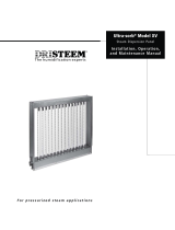
CONDENSATE RETURN PIPING
ULTRA-SORB
®
or
RAPID-SORB
®
125 mm approx. water seal
150 mm minimum
See Table 21-1
DN20 (3/4” BSP)
condensate return
GTS
®
Humidifier
13 mm air vent
Table 20-1
Figure 20-1: Condensate return to humidifier
OM-3010
reifidimuH
ledoM
emocrevootderiuqerthgieH
erusserplanretnireifidimuh
mm
001-STG003
002-STG003
003-STG054
004-STG0
54
18

* Refer to local codes for drain pipe
sizing and maximum temperature
requirements.
RAPID-SORB
®
ASSEMBLY AND INSTALLATION
Horizontal Duct Installation
1. Unpack shipment and verify receipt of all
RAPID-SORB
®
components with packing list. Report
any shortages to the DRI-STEEM factory immediately.
2. Provide necessary access in and around duct work.
3. Locate 25 mm X 38 mm stainless steel channel
inside the duct. Hang the channel from the top of the
duct, centered between duct side walls, with the two
mounting holes provided.
4. If hose cuffs are used, slide cuffs over the open end
of each tube. Install a pair of hose clamps on each tube.
5. Note direction of air flow within duct, then arrange
each dispersion tube so steam will blow perpendicular to
the air flow. Use the hex bolts provided to attach tubes
to overhead 25 mm X 38 mm channel. Do not secure. If
the header is outside the duct punch-out necessary
clearance holes in the base of the duct to slide disper-
sion tubes up from bottom.
6. Choose header location and refer to appropriate
section
a. For a Header Inside the Duct (See figure 21-1):
1. Punch or cut out necessary clearance holes for
RAPID-SORB header. Slide header into the
duct, position header and slide the dispersion
tube hose cuffs or slip couplings over the
header dispersion tube nipples.
2. Position the header so vertical dispersion tubes
are perpendicular to duct and pitch the header to
condensate drain. Secure header to the
mounting bracket. Use escutcheon plates to
secure header where it enters the duct.
3. Check that the dispersion tubes release steam
perpendicular to the air flow. Secure tubes to
the overhead channel. Secure the channel to
the duct, position hose cuffs or slip couplings
over tube and header tube nipples, and secure.
b. For a Header Outside the Duct (See figure 21-2):
1. Position header under dispersion tubes, then
slide hose cuffs or slip couplings over header
dispersion tube nipples.
2. Position the header so dispersion tubes are
perpendicular to duct and pitch the header to
condensate drain. Secure dispersion tubes in
place with the tube escutcheon plates provided.
3. Check the position of the tubes for steam
release perpendicular to the air flow. Secure
tubes to the overhead channel, and secure
channel to the duct. With header pitched to
condensate drain, slip hose cuffs or slip
couplings over tube nipples and secure.
4. Connect a condensate drain to the header,
provide the water trap as shown, and run to
open drain, sized according to governing codes.
5. Attach the header steam supply connector to
main header using the hose cuff and clamps
provided, but do not secure.
6. Route the necessary number of vapor hoses or
pipes from the humidifier tank, position
connector to accept the hoses or pipes and
secure.
Note: Refer to page 17 for vapor hose information on
routing and for alternate vapor hose installation
methods.
Figure 21-1: RAPID-SORB Unit
Header Inside Duct
Figure 21-2: RAPID-SORB Unit
Header Under Duct
25 mm x 38 mm
S.S.T. channel
Nut and
bolt
Duct or
casing
OM-101
OM-748N
Dispersion tube
Orificed
tubelets
Slip coupling
or hose cuff
Optional companion
flange or threaded
connection for hard piping
Condensate drain
(DN20)
Header
20 mm copper
air gap
*Open
drain
15 cm
min.
13 cm
min.
Pitch 1 cm per meter
Top of duct
or casing
Dispersion
tube
Mounting channel
Orificed
tubelets
Hex
head
bolt
View A-A
Slip coupling or hose cuff
GTS
humidifier
Header
*Open drain
Air gap
Condensate
drain, (DN20)
20 mm copper
Escutcheon
plate
Duct
25 mm x 38 mm
S.S.T. channel (by
DRI-STEEM)
* Refer to local codes for drain pipe sizing and maximum temperature
requirements.
Pitch 1 cm per meter
toward drain min.
Hose cuff
and clamps
15 cm
min.
13 cm
min.
19

RAPID-SORB
®
ASSEMBLY AND INSTALLATION
ULTRA-SORB
®
INSTALLATION
See the
ULTRA-SORB Installation Instructions and Maintenance Operation Manual.
Vertical Duct Installation
Install the RAPID-SORB with dispersion tubes and header pitched to condensate drain as shown in figures 22-2,
22-3, and 22-4. See “Instructions for Horizontal Duct” for additional information, as applicable.
Figure 22-4: Elevation View Tube
with Drain
Figure 22-2: Plan View
Steam
supply
1 cm per
metre pitch
minimum
Drain
125 mm min.
150 mm min.
Recommended 150 mm
per metre pitch
Figure 22-3: Elevation View Tube
without Drain
Recommended 2 cm per
metre pitch
Airflow
DN6 (1/4")
Condensate drain
125.mm
min.
150 mm
min.
DN20 (3/4")
coupling
130 mm min.
Open drain
Airflow
OM-700
Piping (by
others)
* Based on total pressure drop in
piping/hose of 1245 Pa.
** For developed length add 50% to
measured length for pipe fittings.
Note: To minimize loss of humidifier
capacity and efficiency, the tubing/
piping should be insulated.
Piping/Hose Sizing from the GTS
®
to a RAPID-SORB panel
Table 22-1: Maximum Steam Carrying Capacity*
esohropaV
sselniatsroreppoC
gnibutleets
.D.IesoH
**m3
htgneldepoleved
h/gk
.D.OgnibuT
**m6
htgneldepoleved
h/gk
)"½1(04ND86)"½1(04ND46
)"2(05ND311)"2(05ND59
----)"3(08ND681
----)"4(001ND813
----)"5(521ND095
----)"6(051ND359
20
/