Page is loading ...

Crestron QM-FBCC-1 & QM-WCC-1
QuickMedia
®
Computer Centers
Operations & Installation Guide

This document was prepared and written by the Technical Documentation department at:
Crestron Electronics, Inc.
15 Volvo Drive
Rockleigh, NJ 07647
1-888-CRESTRON
Regulatory Compliance
Federal Communications Commission (FCC) Compliance Statement
This Class B digital apparatus complies with Canadian ICES-003.
Cet appareil numérique de la classe B est conforme à la norme NMB-003 du Canada.
Industry Canada (IC) Compliance Statement
This device complies with part 15 of the FCC Rules. Operation is subject to the following conditions:
(1) This device may not cause harmful interference and (2) this device must accept any interference received,
including interference that may cause undesired operation.
CAUTION: Changes or modifications not expressly approved by the manufacturer responsible for compliance
could void the user’s authority to operate the equipment.
NOTE: This equipment has been tested and found to comply with the limits for a Class B digital device,
pursuant to part 15 of the FCC Rules. These limits are designed to provide reasonable protection against harmful
interference in a residential installation. This equipment generates, uses and can radiate radio frequency energy
and, if not installed and used in accordance with the instructions, may cause harmful interference to radio
communications. However, there is no guarantee that interference will not occur in a particular installation. If
this equipment does cause harmful interference to radio or television reception, which can be determined by
turning the equipment off and on, the user is encouraged to try to correct the interference by one or more of the
following measures:
Reorient or relocate the receiving antenna
Increase the separation between the equipment and receiver
Connect the equipment into an outlet on a circuit different from that to which the receiver is connected
Consult the dealer or an experienced radio/TV technician for help
As of the date of manufacture, the QM-FBCC/WCC-1 has been tested and found to comply with specifications
for CE marking and standards per EMC and Radiocommunications Compliance Labelling.
All brand names, product names and trademarks are the property of their respective owners.
©2010 Crestron Electronics, Inc.

Crestron QM-FBCC/WCC-1 QuickMedia
®
Computer Centers
Operations & Installation Guide – DOC. 6716B Contents i
Contents
QuickMedia
®
Computer Centers: QM-FBCC-1 & QM-WCC-1 1
Introduction ............................................................................................................................... 1
Features and Functions ................................................................................................ 1
Applications................................................................................................................. 4
Specifications .............................................................................................................. 5
Physical Description .................................................................................................... 8
Setup ........................................................................................................................................ 13
Network Wiring ......................................................................................................... 13
QuickMedia Wiring ................................................................................................... 13
Identity Code ............................................................................................................. 15
Installation ................................................................................................................. 16
Hardware Hookup ..................................................................................................... 19
Programming Software ............................................................................................................ 21
Earliest Version Software Requirements for the PC ......................................................... 21
Programming with Crestron SystemBuilder .............................................................. 21
Programming with SIMPL Windows ........................................................................ 21
Example Program ...................................................................................................... 23
Uploading and Upgrading ........................................................................................................ 24
Establishing Communication ..................................................................................... 24
Programs and Firmware ............................................................................................ 25
Program Checks ........................................................................................................ 25
QM Tools .................................................................................................................. 25
Problem Solving ...................................................................................................................... 26
Troubleshooting ......................................................................................................... 26
Check Network Wiring .............................................................................................. 27
Reference Documents ................................................................................................ 29
Further Inquiries ........................................................................................................ 29
Future Updates .......................................................................................................... 29
Return and Warranty Policies .................................................................................................. 30
Merchandise Returns / Repair Service ...................................................................... 30
CRESTRON Limited Warranty................................................................................. 30


Crestron QM-FBCC/WCC-1 QuickMedia
®
Computer Centers
Operations & Installation Guide – DOC. 6716B QuickMedia
®
: QM-FBCC/WCC-1 1
Single cable signal transmission up to 450 feet (137 meters)
DB15HD RGB computer input
Stereo audio input
Video input signal sensing
QuickMedia transport
Cresnet
®
communications
Low-cost, quick and easy installation
Performs Video signal format management via EDID
Easy setup using Creston SystemBuilder™ software
QM-FBCC-1:
Floor box mountable QuickMedia computer interface
Fits Hubbell SystemOne floor boxes and poke-throughs
Compatible with Hubbell Style Line
®
and Leviton decorator
style faceplate cut-outs
QuickMedia
®
Computer Centers:
QM-FBCC-1 & QM-WCC-1
Introduction
Crestron
®
MediaManager is a comprehensive family of affordable
products fusing high performance AV signal distribution, device control
and facility-wide system management. MediaManager simplifies the art
of Pro AV system design and installation with complete hardware,
software and low-cost wiring solutions. Whether installing a single
boardroom or a campus-wide network of AV systems, MediaManager
delivers power and value far beyond conventional products and designs.
Features and Functions
(Continued on following page)

QuickMedia
®
Computer Centers Crestron QM-FBCC/WCC-1
2 QuickMedia
®
: QM-FBCC/WCC-1 Operations & Installation Guide – DOC. 6716B
Features and Functions
(Continued)
The QM-FBCC-1 QuickMedia
®
Floor Box Computer Center is designed
for mounting in a variety of popular floor boxes and the QM-WCC-1
QuickMedia Wall Plate Computer Center provides a simple wall mount
computer interface solution for any MediaManager system, including
applications ranging from small conference rooms to large banquet halls
and auditoriums.
For simplicity within this guide, the term “QM-FBCC/WCC-1” is used
except where noted.
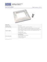
Floor Box Computer Interface (QM-FBCC-1 only)
The QM-FBCC-1 installs cleanly in a Hubbell SystemOne floor box or
poke-through using their Style Line
®
Sub-plate and Universal Cover. Its
slim dimensions and standard screw spacing may also make it suitable
for use with a variety of other floor box systems. An adhesive insert is
included to fit Hubbell Style Line and Leviton decorator style faceplate
cutouts.
Each QM-FBCC-1 provides a single RGB input with stereo audio to
accept a connection from a computer or other RGB source. Built-in
signal sensing can be utilized to trigger automatic input selection and
power control. Wiring for the QM-FBCC-1 is extremely simple requiring
just a single CresCAT
®
QM cable (sold separately).
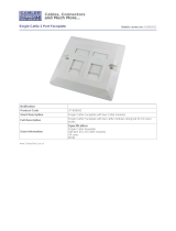
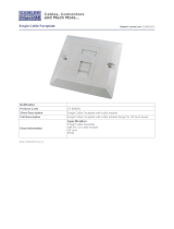
Wall Mount Computer Interface (QM-WCC-1 only)
The QM-WCC-1 installs cleanly in a standard electrical box using a
decorator style faceplate (not supplied). A single RGB input with stereo
audio is provided to accept a connection from a computer or other RGB
source.
QM-WCC-1:
Wall mount QuickMedia computer interface
Integrates with Crestron C2N-CBD and C2N-DB Series
Keypads
Installs alongside third-party LAN jacks and other devices
Available in white or black

Crestron QM-FBCC/WCC-1 QuickMedia
®
Computer Centers
Operations & Installation Guide – DOC. 6716B QuickMedia
®
: QM-FBCC/WCC-1 3
Connectivity for LAN and other signals can easily be added by ganging
the QM-WCC-1 together with other third-party wall plate devices. A
Crestron C2N-CDB or C2N-DB series keypad may also be installed for a
truly complete interface and control solution. Wiring for the QM-WCC-1
is extremely simple, requiring just a single CresCAT-QM cable (sold
separately).
Built-in signal sensing can be utilized to trigger automatic input selection
and power control.
QuickMedia
®
Transport
Using the revolutionary Crestron QuickMedia (QM) transport, input
signals are transmitted from the QM-FBCC/WCC-1 to any QuickMedia
receiver or distribution center over a single inexpensive CAT5e type
cable. Computer resolutions up to 1920 x 1200 pixels at 60 Hz are
supported over cable runs up to 450 feet (137 meters). Audio signals are
transmitted digitally with high performance 24-bit resolution.
QuickMedia dramatically simplifies system design and installation,
affording a higher level of performance at a lower overall cost.
NOTE: For QuickMedia wiring use CresCAT-QM, CresCAT-IM or
quality CAT5e/CAT6 cable with a delay skew of ≤ 15 ns per 328 feet
(100 meters); the maximum aggregate cable length and delay skew
between any QM transmitter (origination point) and QM receiver
(endpoint) is 450 feet (137 meters) and 22 ns; a maximum of two QM
midpoint devices may be inserted in a given QM signal path; exceptions
apply, refer to each respective product manual for details.
MediaManager System Integration
Whether using just one floor box or wall plate computer center or
several, complete system operation can be made transparent to the end
user with all signal routing occurring smoothly under the command of the
MediaManager control system. Complete MediaManager systems are
easy to design, program and adjust from start to finish using Crestron
SystemBuilder™ software.
EDID Format Management
The QM-FBCC/WCC-1 allows for management of the EDID (Extended
Display Identification Data) information sent to the connected source.
Using Crestron Toolbox™ software, the format and resolution

QuickMedia
®
Computer Centers Crestron QM-FBCC/WCC-1
4 QuickMedia
®
: QM-FBCC/WCC-1 Operations & Installation Guide – DOC. 6716B
capabilities of each device can be assessed and managed through the
QM-FBCC/WCC-1, ensuring reliable operation by instructing sources to
output only the resolutions and formats that can be handled by the
displays and system wiring.
Applications
The following diagram shows a QM-FBCC-1 and QM-WCC-1 in a
lecture hall application.
QM-FBCC-1 and QM-WCC-1 in a Lecture Hall Application

Crestron QM-FBCC/WCC-1 QuickMedia
®
Computer Centers
Operations & Installation Guide – DOC. 6716B QuickMedia
®
: QM-FBCC/WCC-1 5
For more information on this and other QM applications, refer to the
latest revision of the Crestron MediaManager Applications Guide
(Doc. 6244), which is available from the Crestron Web site
(www.crestron.com/manuals).
Specifications
Specifications for the QM-FBCC/WCC-1 are listed in the following
table.
QM-FBCC/WCC-1 Specifications
SPECIFICATION
DETAILS
Video
Signal Types
RGB
RGB Formats
RGBHV, RGBS or RGsB
Gain
0 dB (75 ohms terminated)
Maximum Resolution
1920 x 1200 @ 60 Hz (at unity
gain) with maximum cable length
of 450 feet (137 meters) and
maximum compensation at
receiver
Audio
A-D Conversion
24-bit, 48 kHz
Frequency Response
20 Hz to 20 kHz
Power Requirements
Cresnet Power Usage
4 Watts
(0.17 Amps @ 24 Volts DC)
Default Net ID
8E
Minimum 2-Series
Control System Update
File
1, 2
Version 3.155.1240 or later
Environmental
Temperature
41º to 104º F (5º to 40º C)
Humidity
10% to 90% RH (non-condensing)
Heat Dissipation
14 BTU/Hr
(Continued on following page)

QuickMedia
®
Computer Centers Crestron QM-FBCC/WCC-1
6 QuickMedia
®
: QM-FBCC/WCC-1 Operations & Installation Guide – DOC. 6716B
QM-FBCC/WCC-1 Specifications (Continued)
SPECIFICATION
DETAILS
Enclosure
QM-FBCC-1
Mountable on either side of a
Hubbell SystemOne floor box or
poke-through using Style Line
®
Sub-plate (S1SP) and Universal
Cover or any floor box with a
standard wall plate screw spacing
(3.81 inch, 97 mm), 2.1 inch (54
mm) high x 0.8 inch (21 mm) wide
minimum faceplate cut-out and 2.1
inch (54 mm) minimum depth
behind faceplate;
Included insert accommodates
Hubbell Style Line and Leviton
decorator style faceplate cut-outs
QM-WCC-1
Flush Wall Mount
1-gang mountable in a standard
electrical box, 2.1 inch (54 mm)
deep minimum;
Requires decorator style faceplate
(not included)
Rack Mount
Mountable to a single 19-inch EIA
rack rail
Dimensions
Height
QM-FBCC-1
QM-WCC-1
4.14 in (105 mm)
4.12 in (105 mm)
Width
QM-FBCC-1
QM-WCC-1
1.30 in (33 mm)
1.72 in (44 mm)
Depth
1.74 in (44 mm)
(Continued on following page)

Crestron QM-FBCC/WCC-1 QuickMedia
®
Computer Centers
Operations & Installation Guide – DOC. 6716B QuickMedia
®
: QM-FBCC/WCC-1 7
QM-FBCC/WCC-1 Specifications (Continued)
SPECIFICATION
DETAILS
Weight
QM-FBCC-1
6 oz (155 g)
QM-WCC-1
8 oz (210 g)
Available Models
QM-FBCC-1
QuickMedia Floor Box Computer
Center, Black
QM-WCC-1-B-T
QuickMedia Wall Plate Computer
Center, Single Input, Black
QM-WCC-1-W-T
QuickMedia Wall Plate Computer
Center, Single Input, White
Available Accessories
CresCAT-IM
iMedia Cable
CresCAT-QM
QuickMedia Cable
Cresnet
Cresnet Control Cable
1. The latest software versions can be obtained from the Crestron Web site. Refer to
the NOTE following these footnotes.
2. Crestron 2-Series control systems include the AV2 and PRO2. Consult the latest
Crestron Product Catalog for a complete list of 2-Series control systems.
NOTE: Crestron software and any files on the Web site are for
authorized Crestron dealers and Crestron Authorized Independent
Programmers (CAIP) only. New users may be required to register to
obtain access to certain areas of the site (including the FTP site).

QuickMedia
®
Computer Centers Crestron QM-FBCC/WCC-1
8 QuickMedia
®
: QM-FBCC/WCC-1 Operations & Installation Guide – DOC. 6716B
Physical Description
This section provides information on the connections, controls and
indicators available on your QM-FBCC/WCC-1.
QM-FBCC-1 Physical View
QM-WCC-1 Physical View

Crestron QM-FBCC/WCC-1 QuickMedia
®
Computer Centers
Operations & Installation Guide – DOC. 6716B QuickMedia
®
: QM-FBCC/WCC-1 9
QM-FBCC-1 Overall Dimensions (Front and Rear Views)
1
2
3
4
4.14 in
(105 mm)
1.30 in
(33 mm)
5
6
QM-FBCC-1 Overall Dimensions (Side and Bottom Views)
6
0.13 in
(3 mm)
1.55 in
(39 mm)
1.74 in
(44mm)
7

QuickMedia
®
Computer Centers Crestron QM-FBCC/WCC-1
10 QuickMedia
®
: QM-FBCC/WCC-1 Operations & Installation Guide – DOC. 6716B
QM-WCC-1 Overall Dimensions (Front and Rear Views)
5
6
1
2
3
4
1.72 in
(44 mm)
4.12 in
(105 mm)
QM-WCC-1 Overall Dimensions (Side and Bottom Views)
6
0.19 in
(5 mm)
1.50 in
(38 mm)
1.74 in
(44 mm)
7

Crestron QM-FBCC/WCC-1 QuickMedia
®
Computer Centers
Operations & Installation Guide – DOC. 6716B QuickMedia
®
: QM-FBCC/WCC-1 11
Connectors, Controls & Indicators
#
CONNECTORS
1
,
CONTROLS &
INDICATORS
DESCRIPTION
1
PWR LED
(1) Green LED, indicates 24
Volts DC power supplied from
Cresnet network
2
AUDIO
(1) 3.5 mm TRS mini phone
jack;
Unbalanced stereo line level
audio input;
Input impedance: 10 kΩ;
Maximum input level: 1 V
rms
3
NET LED
(1) Yellow LED, indicates
communication with Cresnet
system
4
PC
(1) DB15HD female;
RGB(VGA) input;
Formats: RGBHV, RGBS,
RGsB;
Input impedance: 75 Ω
Sync impedance: 1 kΩ
Maximum input: level: 1 V
p-p
Maximum sync level: 5 V
p-p
Signal sensing on H-SYNC only
5
NET
(1) 4-pin 3.5 mm detachable
terminal block;
Cresnet slave port;
Connects to Cresnet control
network via CresCAT-QM or
Cresnet cable
24: Power (24 Volts DC)
Y: Data
Z: Data
G: Ground
(Continued on following page)

QuickMedia
®
Computer Centers Crestron QM-FBCC/WCC-1
12 QuickMedia
®
: QM-FBCC/WCC-1 Operations & Installation Guide – DOC. 6716B
Connectors, Controls, & Indicators (Continued)
#
CONNECTORS
1
,
CONTROLS &
INDICATORS
DESCRIPTION
6
QM
2, 3
8
1
(1) 8-wire RJ-45 female,
QuickMedia output port;
Connects to QM input port of
any QuickMedia device via
CresCAT-QM or CresCAT-IM
cable
7
Grounding Wire
(1) Flying lead, grounding wire
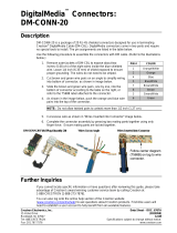
1. An interface connector for the NET port is provided with the unit.
2. For QuickMedia wiring, use CresCAT-QM, CresCAT-IM or quality
CAT5e/CAT6 cable with a delay skew of ≤ 15 ns per 328 feet (100 meters); the
maximum aggregate cable length and delay skew between any QM transmitter
(origination point) and QM receiver (endpoint) is 450 feet (137 meters) and 22 ns;
a maximum of two QM midpoint devices may be inserted in a given QM signal
path; exceptions apply, refer to each respective product manual for details.
3. The eight-pin RJ-45 QuickMedia transport port accepts CAT5E/CAT6 carrying
audio, video and microphone signals. The QM input port conforms to the 568B
wiring standard. Refer to the following table for connector pinouts.
RJ-45 PIN
NUMBER
WIRE COLORS
(EIA 568B)
QM
ASSIGNMENT:
RGB
QM ASSIGNMENT:
COMPOSITE, S-VIDEO,
COMPONENT AND
AUDIO
1
WHITE/ORANGE
- RGB RED
- CHROMINANCE (- P
r
)
2
ORANGE
+ RGB RED
+ CHROMINANCE (+ P
r
)
3
WHITE/GREEN
- RGB GREEN
- LUMINANCE (- Y)
4
BLUE
+ DIGITAL AUDIO
+ DIGITAL AUDIO
5
WHITE/BLUE
- DIGITAL AUDIO
- DIGITAL AUDIO
6
GREEN
+ RGB GREEN
+ LUMINANCE (+ Y)
7
WHITE/BROWN
- RGB BLUE
- COMPOSITE (- P
b
)
8
BROWN
+ RGB BLUE
+ COMPOSITE (+ P
b
)

Crestron QM-FBCC/WCC-1 QuickMedia
®
Computer Centers
Operations & Installation Guide – DOC. 6716B QuickMedia
®
: QM-FBCC/WCC-1 13
Setup
Network Wiring
When wiring the Cresnet
®
network, consider the following:
Use Crestron Certified Wire.
Use Crestron power supplies for Crestron equipment.
Provide sufficient power to the system.
CAUTION: Insufficient power can lead to unpredictable results
or damage to the equipment. Please use the Crestron Power
Calculator to help calculate how much power is needed for the
system (www.crestron.com/calculators).
For networks with 20 or more devices, use a Cresnet Hub/Repeater
(CNXHUB) to maintain signal quality.
For more details, refer to “Check Network Wiring” which starts on page
27.
QuickMedia Wiring
The Crestron QuickMedia cable (sold under the name “CresCAT-QM”)
contains one CAT5E cable and one Cresnet cable in Siamese jackets.
Installation of any QM device is as simple as installing CresCAT-QM
wires from the output of one device to the input of another. Installations
are flexible, affordable and fast. For more information, refer to the latest
revision of the Crestron MediaManager Applications Guide (Doc. 6244),
which is available from the Crestron Web site.

QuickMedia
®
Computer Centers Crestron QM-FBCC/WCC-1
14 QuickMedia
®
: QM-FBCC/WCC-1 Operations & Installation Guide – DOC. 6716B
CresCAT-QM Cable
CresCAT-QM
Cable
NOTE: Do not untwist the two wires in a single pair for more than 1/3-
1/2” (8–12 mm) when making a connection. The twists are critical to
canceling out interference between the wires.
The aggregate cable length of a signal path originating at a
QM-FBCC/WCC-1 and terminating at a QM receiver must not exceed
450 feet (137 meters). Video signals may experience a loss of quality
over very long lengths of cable. This phenomenon is due to the added
resistance and capacitance of longer cable lengths and is not peculiar to
either Crestron and/or QuickMedia systems. To ensure sufficient
bandwidth, the maximum aggregate cable length should not exceed 450
feet. The use of lower-resolution signals may allow increased cable
length but must be tested by the installer with the sources to be used. The
QM pin assignment is based on the EIA/TIA 568B RJ-45 Jack standard.
NOTE: When using CresCAT-QM wiring, four additional wires are
included for making Cresnet connections.
When connecting multiple QM devices, the route between a QM
origination point (transmitter) and a QM endpoint (receiver) cannot have

Crestron QM-FBCC/WCC-1 QuickMedia
®
Computer Centers
Operations & Installation Guide – DOC. 6716B QuickMedia
®
: QM-FBCC/WCC-1 15
more than two midpoints (e.g. QM-MD7x2 or other QM switchers).
Refer to the following diagram when configuring a QM network.
NOTE: The aggregate length from transmitter to receiver cannot have a
delay skew of more than 22 ns.
QM Network Topology
Identity Code
NOTE: This device does not support TSID.
The Net ID of the QM-FBCC/WCC-1 has been factory set to 8E. The
Net IDs of multiple QM-FBCC/WCC-1 devices in the same system must
be unique. Net IDs are changed from a personal computer (PC) via
Crestron Toolbox™ (refer to “Establishing Communication” on page 24).
When setting the Net ID, consider the following:
The Net ID of each unit must match an ID code specified in the
SIMPL™ Windows program.
Each network device must have a unique Net ID.
For more details, refer to the Crestron Toolbox help file.

QuickMedia
®
Computer Centers Crestron QM-FBCC/WCC-1
16 QuickMedia
®
: QM-FBCC/WCC-1 Operations & Installation Guide – DOC. 6716B
Installation
The QM-FBCC/WCC-1 should be used in a well-ventilated area. The
venting holes should not be obstructed under any circumstances.
To prevent overheating, do not operate this product in an area that
exceeds the environmental temperature range listed in the table of
specifications.
The following tools and accessories are required for installation of a
QM-FBCC/WCC-1:
Hubbell
®
SystemOne
®
floor box S1SP plate (for QM-FBCC-1,
not supplied)
Standard 1-gang electrical box (for QM-WCC-1, not supplied)
Decorator style or equivalent wall plate (for QM-WCC-1, not
supplied)
Flat head screwdriver (not supplied)
Two #06-32 x 1” screws (included)
Insert, black or white (included)
After Cresnet and QM wiring has been installed and verified, use the
following procedure to install the QM-FBCC/WCC-1.
1. Turn system power OFF.
2. Connect the Cresnet and QM cables to the QM-FBCC/WCC-1’s
Cresnet and QM ports, respectively.
3. Attach the QM-FBCC/WCC-1 to the floor box or electrical box
using the two supplied #06-32 x 1” screws.
CAUTION: Excess wire that is pinched between the
QM-FBCC/WCC-1 and the floor box or electrical box could short out.
Make sure all excess wire is completely inside the floor box or electrical
box and not between the box and the QM-FBCC/WCC-1.
4. For the QM-WCC-1, attach the wall plate using the screws that
came with the wall plate.
5. Remove the backing, which covers the adhesive, on the insert and
attach the insert to the QM-FBCC/WCC-1, as shown in the
illustrations on the following pages.
6. Turn system power ON.
/