
Enclose this document with the operating instructions of the
machine.
Supplement to operating
instructions
Document number: 150001776_00_en
Version: 02/11/2021
Rotary rakes
Software version: D2515020138300003
Error messages and information messages

Table of contents
2
Rotary rakes
Supplement to operating instructions 150001776_00_en
1 Information on this document .................................................................................................. 3
1.1 Validity ......................................................................................................................................... 3
1.2 Re-ordering.................................................................................................................................. 3
1.3 Applicable documents.................................................................................................................. 3
2 Safety .......................................................................................................................................... 4
2.1 Meaning of the supplement to the operating instructions ............................................................ 4
3 Error messages.......................................................................................................................... 5
3.1 Possible error types (FMI)............................................................................................................ 5
3.2 Error list........................................................................................................................................ 6
4 Information messages............................................................................................................. 20
4.1 Information messages ............................................................................................................... 20
Index.......................................................................................................................................... 23

Information on this document 1
Validity 1.1
Rotary rakes
Supplement to operating instructions 150001776_00_en 3
1 Information on this document
1.1 Validity
This document is valid for:
KS403-42 (Swadro TC 1370)
1.2 Re-ordering
You can request a replacement document if this document became completely or partly
unusable, or if you need it in a different language. Please specify the document number shown
on the cover page in your order. Alternatively, you can download the document online from
KRONE MEDIA https://media.mykrone.green.
1.3 Applicable documents
To ensure that the machine is used safely and as intended, observe the following further
applicable documents.
• Operating instructions of the respective machine

2 Safety
2.1 Meaning of the supplement to the operating instructions
4
Rotary rakes
Supplement to operating instructions 150001776_00_en
2 Safety
WARNING
Risk of injury due to non-observance of relevant safety instructions
If the relevant safety instructions are not observed, persons may be seriously injured or killed.
In order to avoid accidents, the relevant safety instructions in the operating instructions
must be read and observed.
WARNING
Risk of injury due to non-observance of safety routines
If the relevant safety routines are not observed, persons may be seriously injured or killed.
In order to avoid accidents, the safety routines in the operating instructions must be read
and observed.
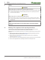
INFO
Depending on the machine type, the basic safety instructions can be found in the chapter
“Safety”, “Basic Safety Instructions” or in the chapter “Safety” of the machine operating
instructions.
2.1 Meaning of the supplement to the operating instructions
The supplement to the operating instructions is an important document and a part of the
machine. It is aimed at the user and contains safety-relevant information.
If the supplement to the operating instructions is not observed, people may be seriously injured
or killed.
Read in full and observe the “Safety” chapter of the corresponding operating instructions
before using the machine for the first time,see Page3.
Before working, also read and observe the respective sections of the corresponding
operating instructions,see Page3.
Keep the supplement to the operating instructions ready to hand for the user of the machine.
Hand over the supplement to the operating instructions to subsequent users.

Error messages 3
Possible error types (FMI) 3.1
Rotary rakes
Supplement to operating instructions 150001776_00_en 5
3 Error messages
WARNING
Risk of injury to persons and damage to machines if error messages are ignored
If error messages are ignored and the fault is not rectified, there is a risk of injury to persons
and/or severe damage to the machine.
Eliminate the disturbance when an error message is displayed, see Page6.
If the fault cannot be rectified, contact KRONE service partner.
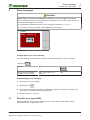
CAN1
KMC - 520192- 19
EQG000-034
Configuration of an error message
The error message is configured according to the following sample: e.g. error message
"520192-19
CAN1
"
520192 19
CAN1
SPN (Suspect Parameter
Number) = error number
FMI = type of error, see
Page5
Icon
Acknowledging error message
Note down the error message.
Briefly press on .
ÆThe acoustic signal stops and the error display is no longer indicated. If the fault occurs
again, the error message will be displayed again.
Rectify the error, see Page6.
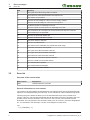
3.1 Possible error types (FMI)
There are different types of errors which are shown under the term FMI (Failure Mode
Identification) with an appropriate code.

3 Error messages
3.2 Error list
6
Rotary rakes
Supplement to operating instructions 150001776_00_en
FMI Meaning
0 The upper limit value was greatly exceeded.
1 The lower limit value was far below the required one.
2 The data is not permitted.
3 There is an overvoltage or a short circuit to supply voltage.
4 There is an undervoltage or a short circuit to ground.
5 A cable is broken or amperage is too low.
6 There is a short circuit to ground or amperage is too low.
7 The mechanics do not respond or the expected result was not achieved.
8 The frequency is not permitted.
9 There is an abnormal update rate.
10 There is an abnormal rate of change.
11 The error cause is unknown.
12 There is an internal error.
13 The values of the calibration are outside the value range.
14 Particular instructions are required.
15 The upper limit value has been reached.
16 The upper limit value has been exceeded.
17 The lower limit value has been reached.
18 The lower limit value has not been reached.
19 There is a CAN communication failure.
20 The data deviates upwards.
21 The data deviates downwards.
31 The condition has been fulfilled.
3.2 Error list
Overview of the control units
Abbreviation Explanation
KMC KRONE Machine Controller
General information on error causes
The sequence of the possible causes listed here was selected such that the easiest tests with
regard to accessibility/handling are listed first. This is intended to make troubleshooting easier.
Following the given references takes you to the individual test steps of the possible error
causes. If the error has not been eliminated after all test steps have been completed, the next
possible cause must be checked or the next error in the error list of the terminal must be
eliminated. The components to be checked in detail, such as contacts, connector designations,
etc., are not listed in the test steps. Use the circuit diagram to locate them.
>>>
2en_Fehlerliste [}7]

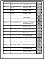
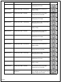
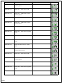
Error list
Software version: D2515020138500003_500,
D2515020142000003_500
Control unit: KMC

Page 1
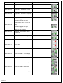
Error number Error text Description Figure
KMC-520192-19 CAN1 - CAN disturbance between
control units
There is a CAN disturbance between
control units on CAN 1.
KMC-520193-19 CAN2 - CAN disturbance between
control units
There is a CAN disturbance between
control units on CAN 2.
KMC-520194-19 CAN3 - CAN disturbance between
control units
There is a CAN disturbance between
control units on CAN 3.
KMC-520195-19 CAN4 - CAN disturbance between
control units
There is a CAN disturbance between
control units on CAN 4.
KMC-520198-12 Control unit - Internal Error An internal error in the control unit
which was actuated by defective
software or hardware.
KMC-520232-12 Vehicle identification number -
Internal Error
Vehicle identification number has not
been initialised.
KMC-520234-31 System check with KMC failed With the KMC the cross-controller
adjustment of system-relevant
machine data has failed.
KMC-521100-3 Voltage group UB1 - Overvoltage The input voltage of the corresponding
voltage group is too high.
KMC-521100-4 Voltage group UB1 - Undervoltage The input voltage of the corresponding
voltage group is too low.
KMC-521100-5 Voltage group UB1 - Ground fault A ground fault has occurred on the
supply voltage.
KMC-521100-6 Voltage group UB1 - Overload The maximum load on the supply
voltage has been exceeded.
KMC-521101-3 Voltage group UB2 - Overvoltage The input voltage of the corresponding
voltage group is too high.
KMC-521101-4 Voltage group UB2 - Undervoltage The input voltage of the corresponding
voltage group is too low.
KMC-521101-5 Voltage group UB2 - Ground fault The maximum load on the supply
voltage has been exceeded.
KMC-521101-6 Voltage group UB2 - Overload The maximum load on the supply
voltage has been exceeded.
KMC-521102-3 Voltage group UB3 - Overvoltage The input voltage of the corresponding
voltage group is too high.

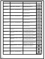
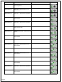
Page 2
Error number Error text Description Figure
KMC-521102-4 Voltage group UB3 - Undervoltage The input voltage of the corresponding
voltage group is too low.
KMC-521102-5 Voltage group UB3 - Ground fault A ground fault has occurred on the
supply voltage.
KMC-521102-6 Voltage group UB3 - Overload The maximum load on the supply
voltage has been exceeded.
KMC-521103-3 Voltage group UB4 - Overvoltage The input voltage of the corresponding
voltage group is too high.
KMC-521103-4 Voltage group UB4 - Undervoltage The input voltage of the corresponding
voltage group is too low.
KMC-521103-5 Voltage group UB4 - Ground fault A ground fault has occurred on the
supply voltage.
KMC-521103-6 Voltage group UB4 - Overload The maximum load on the supply
voltage has been exceeded.
KMC-521104-3 Voltage group UB5 - Overvoltage The input voltage of the corresponding
voltage group is too high.
KMC-521104-4 Voltage group UB5 - Undervoltage The input voltage of the corresponding
voltage group is too low.
KMC-521104-5 Voltage group UB5 - Ground fault A ground fault has occurred on the
supply voltage.
KMC-521104-6 Voltage group UB5 - Overload The maximum load on the supply
voltage has been exceeded.
KMC-521105-3 Voltage group UB6 - Overvoltage The input voltage of the corresponding
voltage group is too high.
KMC-521105-4 Voltage group UB6 - Undervoltage The input voltage of the corresponding
voltage group is too low.
KMC-521105-5 Voltage group UB6 - Ground fault A ground fault has occurred on the
supply voltage.
KMC-521105-6 Voltage group UB6 - Overload The maximum load on the supply
voltage has been exceeded.
KMC-521106-11 Supply voltage sensors - General
disturbance
The voltage has been switched off due
to an overload or a short circuit on the
supply voltage of the sensors.

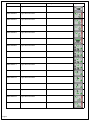
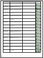
Page 3
Error number Error text Description Figure
KMC-521107-3 Supply voltage - Overvoltage The power supply on the UE
connection is too high.
KMC-521107-4 Supply voltage - Undervoltage The power supply on the UE
connection is too low.
KMC-521108-11 Control unit - General disturbance The voltage group relay UB1 has not
passed the self-test.
KMC-521109-11 Control unit - General disturbance The voltage group relay UB2 has not
passed the self-test.
KMC-521110-11 Control unit - General disturbance The voltage group relay UB3 has not
passed the self-test.
KMC-521111-11 Control unit - General disturbance The voltage group relay UB4 has not
passed the self-test.
KMC-521112-11 Control unit - General disturbance The voltage group relay UB5 has not
passed the self-test.
KMC-521113-11 Control unit - General disturbance The voltage group relay UB6 has not
passed the self-test.
KMC-521114-11 Sensor supply voltage U1 - General
disturbance
The voltage group Uext1 for supplying
the sensors is defective, for example
due to overload or short circuit.
KMC-521115-11 Sensor supply voltage U2 - General
disturbance
The voltage group Uext2 for supplying
the sensors is defective, for example
due to overload or short circuit.
KMC-521116-11 Sensor supply voltage U3 - General
disturbance
The voltage group Uext3 for supplying
the sensors is defective, for example
due to overload or short circuit.
KMC-521117-11 Sensor supply voltage U4 - General
disturbance
The voltage group Uext4 for supplying
the sensors is defective, for example
due to overload or short circuit.
KMC-521118-11 Voltage group relay UB2 - General
disturbance
Platform error only for BiG X: A
disturbance has been detected at the
intake/header. The voltage group relay
UB2 was therefore switched off.
KMC-521320-2 Machine configuration - Logic error
electronics
Configuration of the machine is not
compatible with the hardware.
KMC-521350-11 Control unit - General disturbance
KMC-521351-11 Control unit - General disturbance

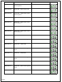
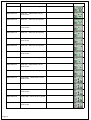
Page 4
Error number Error text Description Figure
KMC-522001-2 Logic error electronics
KMC-522002-7 Logic fault mechanics
KMC-522003-7 Logic fault mechanics
KMC-522004-7 Logic fault mechanics
KMC-522005-7 Logic fault mechanics
KMC-522006-7 Logic fault mechanics
KMC-522008-7 Logic fault mechanics
KMC-522009-7 Logic fault mechanics
KMC-522010-7 Logic fault mechanics
KMC-522011-7 Logic fault mechanics
KMC-522012-7 Logic fault mechanics
KMC-522013-7 Logic fault mechanics
KMC-522014-7 Logic fault mechanics
KMC-522015-7 Logic fault mechanics
KMC-522016-7 Logic fault mechanics
KMC-522017-7 Logic fault mechanics

Page 5
Error number Error text Description Figure
KMC-522018-7 Logic fault mechanics
KMC-522019-7 Logic fault mechanics
KMC-522020-7 Logic fault mechanics
KMC-522021-7 Logic fault mechanics
KMC-522022-7 Logic fault mechanics
KMC-522023-16 Upper limit value exceeded The universal shaft is rotating faster
than permitted.
KMC-522079-7 Logic fault mechanics
KMC-522101-3 Sensor B01 - Cable break
KMC-522101-4 Sensor B01 - Short circuit to ground
or UB
KMC-522102-3 Sensor B02 - Cable break
KMC-522102-4 Sensor B02 - Short circuit to ground
or UB
KMC-522103-3 Sensor B03 - Cable break
KMC-522103-4 Sensor B03 - Short circuit to ground
or UB
KMC-522104-3 Sensor B04 - Cable break
KMC-522104-4 Sensor B04 - Short circuit to ground
or UB
KMC-522105-3 Sensor B05 - Short circuit to UB

Page 6
Error number Error text Description Figure
KMC-522105-4 Sensor B05 - Cable break or short
circuit to ground
KMC-522106-3 Sensor B06 - Short circuit to UB
KMC-522106-4 Sensor B06 - Cable break or short
circuit to ground
KMC-522107-3 Sensor B07 - Short circuit to UB
KMC-522107-4 Sensor B07 - Cable break or short
circuit to ground
KMC-522108-3 Sensor B08 - Short circuit to UB
KMC-522108-4 Sensor B08 - Cable break or short
circuit to ground
KMC-522109-3 Sensor B09 - Cable break
KMC-522109-4 Sensor B09 - Short circuit to ground
or UB
KMC-522110-3 Sensor B10 - Cable break
KMC-522110-4 Sensor B10 - Short circuit to ground
or UB
KMC-522111-3 Sensor B11 - Cable break
KMC-522111-4 Sensor B11 - Short circuit to ground
or UB
KMC-522112-3 Sensor B12 - Cable break
KMC-522112-4 Sensor B12 - Short circuit to ground
or UB
KMC-522113-3 Sensor B13 - Short circuit to UB

Page 7
Error number Error text Description Figure
KMC-522113-4 Sensor B13 - Cable break or short
circuit to ground
KMC-522114-3 Sensor B14 - Short circuit to UB
KMC-522114-4 Sensor B14 - Cable break or short
circuit to ground
KMC-522115-3 Sensor B15 - Short circuit to UB
KMC-522115-4 Sensor B15 - Cable break or short
circuit to ground
KMC-522116-3 Sensor B16 - Cable break
KMC-522116-4 Sensor B16 - Short circuit to ground
or UB
KMC-522117-3 Sensor B17 - Cable break
KMC-522117-4 Sensor B17 - Short circuit to ground
or UB
KMC-522118-3 Sensor B18 wheel sensor - Cable
break
KMC-522118-4 Sensor B18 wheel sensor - Short
circuit to ground or UB
KMC-522119-3 Sensor B19 - Short circuit to UB
KMC-522119-4 Sensor B19 - Cable break or short
circuit to ground
KMC-522120-3 Sensor B20 - Cable break
KMC-522120-4 Sensor B20 - Short circuit to ground
or UB
KMC-522121-3 Sensor B21 - Short circuit to UB

Page 8
Error number Error text Description Figure
KMC-522121-4 Sensor B21 - Cable break or short
circuit to ground
KMC-522301-3 Valve Q01 - Cable break or short
circuit to UB
KMC-522301-6 Valve Q01 - Short circuit to ground
KMC-522302-3 Valve Q02 - Cable break or short
circuit to UB
KMC-522302-6 Valve Q02 - Short circuit to ground
KMC-522303-3 Valve Q03 Pilot valve - Cable break or
short circuit to UB
KMC-522303-6 Valve Q03 Pilot valve - Short circuit to
ground
KMC-522304-3 Valve Q04 - Cable break or short
circuit to UB
KMC-522304-6 Valve Q04 - Short circuit to ground
KMC-522305-3 Valve Q05 - Cable break or short
circuit to UB
KMC-522305-6 Valve Q05 - Short circuit to ground
KMC-522306-3 Valve Q06 - Cable break or short
circuit to UB
KMC-522306-6 Valve Q06 - Short circuit to ground
KMC-522308-3 Valve Q09 - Cable break or short
circuit to UB
KMC-522308-6 Valve Q09 - Short circuit to ground
KMC-522309-3 Valve Q10 - Cable break or short
circuit to UB

Page 9
Error number Error text Description Figure
KMC-522309-6 Valve Q10 - Short circuit to ground
KMC-522310-3 Valve Q07 - Cable break or short
circuit to UB
KMC-522310-6 Valve Q07 - Short circuit to ground
KMC-522311-3 Valve Q08 - Cable break or short
circuit to UB
KMC-522311-6 Valve Q08 - Short circuit to ground
KMC-522312-3 Valve Q13 - Cable break or short
circuit to UB
KMC-522312-6 Valve Q13 - Short circuit to ground
KMC-522313-3 Valve Q14 - Cable break or short
circuit to UB
KMC-522313-6 Valve Q14 - Short circuit to ground
KMC-522314-3 Valve Q15 - Cable break or short
circuit to UB
KMC-522314-6 Valve Q15 - Short circuit to ground
KMC-522315-3 Valve Q16 - Cable break or short
circuit to UB
KMC-522315-6 Valve Q16 - Short circuit to ground
KMC-522317-3 Valve Q12 - Cable break or short
circuit to UB
KMC-522317-6 Valve Q12 - Short circuit to ground
KMC-522318-3 Valve Q11 - Cable break or short
circuit to UB

Page 10
Error number Error text Description Figure
KMC-522318-6 Valve Q11 - Short circuit to ground
KMC-522319-3 Valve Q21 - Cable break or short
circuit to UB
KMC-522319-6 Valve Q21 - Short circuit to ground
KMC-522331-3 Valve Q17 - Cable break or short
circuit to UB
KMC-522331-6 Valve Q17 - Short circuit to ground
KMC-522332-3 Valve Q18 - Cable break or short
circuit to UB
KMC-522332-6 Valve Q18 - Short circuit to ground
KMC-522333-3 Valve Q19 - Cable break or short
circuit to UB
KMC-522333-6 Valve Q19 - Short circuit to ground
KMC-522334-3 Valve Q20 - Cable break or short
circuit to UB
KMC-522334-6 Valve Q20 - Short circuit to ground
KMC-522341-3 Engine M01 - Cable break or short
circuit to UB
KMC-522341-6 Engine M01 - Short circuit to ground
KMC-522342-3 Engine M02 - Cable break or short
circuit to UB
KMC-522342-6 Engine M02 - Short circuit to ground
KMC-522343-3 Engine M03 - Cable break or short
circuit to UB

Page 11
Error number Error text Description Figure
KMC-522343-6 Engine M03 - Short circuit to ground
KMC-522344-3 Engine M04 - Cable break or short
circuit to UB
KMC-522344-6 Engine M04 - Short circuit to ground
KMC-522351-3 Lamp
- E01 Working light front left
- E02 Working light front right
- E03
- Cable break or short circuit to UB
KMC-522351-6 Lamp
- E01 Working light front left
- E02 Working light front right
- E03
- Short circuit to ground
KMC-522354-3 Valve Q22 - Cable break or short
circuit to UB
KMC-522354-6 Valve Q22 - Short circuit to ground
KMC-522510-19 ISB - Malfunction
KMC-522511-12 Internal Error
KMC-522540-19 Control A30 KMB 1 - Malfunction
KMC-522541-4 Control A30 KMB 1 - Undervoltage
KMC-522542-12 Control A30 KMB 1 - Internal Error
KMC-522543-3 Control A30 KMB 1 - Overvoltage
KMC-522545-19 Control A31 KMB 2 - Malfunction
KMC-522546-4 Control A31 KMB 2 - Undervoltage

Page 12
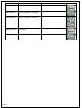
Error number Error text Description Figure
KMC-522547-12 Control A31 KMB 2 - Internal Error
KMC-522548-3 Control A31 KMB 2 - Overvoltage
KMC-522560-19 Control A31 KMB 2 - Malfunction
KMC-522561-4 Undervoltage
KMC-522562-12 Internal Error
KMC-522565-3 Overvoltage

4 Information messages
4.1 Information messages
20
Rotary rakes
Supplement to operating instructions 150001776_00_en
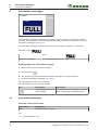
4 Information messages
FULL
I - 2001
EQ001-223
An information message is indicated in the display to ensure smooth running of the machine
functions. At the same time, an audio signal will be heard (continuous horn signal). For a list of
information messages see Page20.
The information message is structured according to the following sample: e.g. information
message "I-2001
FULL
"
I 2001
FULL
Information message Information message number Icon
Acknowledging the information message
Make a note of the information message.
Briefly press on .
ÆThe acoustic signal stops and the information message is no longer indicated.
Check the information message, see Page20.
The following key function can be selected:
The following key functions can be selected:
Icon Designation Explanation
Acknowledging the inform-
ation message
If the disturbance occurs again, the inform-
ation message will be displayed again.
4.1 Information messages
Overview of the control units
Abbreviation Explanation
KMC KRONE Machine Controller
>>>
2en_Infomeldungen [}21]
Page is loading ...
Page is loading ...
Page is loading ...
Page is loading ...
-
 1
1
-
 2
2
-
 3
3
-
 4
4
-
 5
5
-
 6
6
-
 7
7
-
 8
8
-
 9
9
-
 10
10
-
 11
11
-
 12
12
-
 13
13
-
 14
14
-
 15
15
-
 16
16
-
 17
17
-
 18
18
-
 19
19
-
 20
20
-
 21
21
-
 22
22
-
 23
23
-
 24
24


Krone EzBA Software KS403-42 Operating instructions
- Type
- Operating instructions
- This manual is also suitable for
Ask a question and I''ll find the answer in the document
Finding information in a document is now easier with AI
Related papers
-
Krone Messages - Parameters Operating instructions
-
Krone EzBA Meldungen – Parameter Operating instructions
-
-
-
-
-
-
-
-
Other documents
-
KMC Controls WinControl XL Software Manual
-
KMC BAC-5801/5802 Installation guide
-
-
Kenwood TK-190 User manual
-
-
-
Magtek ExpressCard 1000 Operating instructions
-
Lennox KMC BACnet Module Kits (16X70, 16X71, 16X72, and 17A08) Installation guide
-
Moxa EDS-518A-MM-ST-T Datasheet
-