Page is loading ...

Doc. no.: 9.17.079 rev. E Date: 04-07-2019
ATTENTION
Please read this document carefully before installing and operating the product.
Not following the guidelines could result in personal injury and/or damage to the equipment.
Vapor Delivery Module
Instruction Manual

Bronkhorst®
Instruction Manual Vapor Delivery Module 9.17.079E2
Copyright
© 2019 Bronkhorst High-Tech B.V.
All rights reserved. No part of this publication may be reproduced, distributed, or transmitted in any form or by any means,
without the prior written permission of the publisher.
Disclaimer
This document has been reviewed and is believed to be accurate. Bronkhorst High-Tech B.V. does not assume liability for
errors, inaccuracies or absence of information. The material in this document merely serves information and illustration
purposes; no rights can be derived from its contents.
Bronkhorst High-Tech B.V. reserves the right to modify or improve its products and documentation without informing
anyone. The information contained in this document is subject to change without notice. Device specifications and the
contents of the package may deviate from what is stated in this document.
Symbols in this document
Important information. Disregarding this information could increase the risk of damage to the equipment, or the risk of
personal injuries.
Helpful information. This information will facilitate the use of the instrument and/or contribute to its optimal
performance.
Additional information available on the internet or from your Bronkhorst representative.
Receipt of equipment
Check the outside packaging box for damage incurred during shipment. If the box is damaged, then the local carrier must
be notified at once regarding his liability, if so required. At the same time a report should be submitted to your Bronkhorst
representative.
Carefully remove the equipment from the box. Verify that the contents of the package was not damaged during shipment.
Should the equipment be damaged, then the local carrier must be notified at once regarding his liability, if so required. At
the same time a report should be submitted to your Bronkhorst representative.
·Check the packing list to ensure that you received all of the items included in the scope of delivery
·Do not discard spare or replacement parts with the packaging material
Refer to Removal and return instructions about return shipment procedures.
Equipment storage
The equipment should be stored in its original package in a cupboard warehouse or similar. Care should be taken not to
subject the equipment to excessive temperatures or humidity.

Bronkhorst®
Instruction Manual Vapor Delivery Module9.17.079E 3
Warranty
Bronkhorst® products are warranted against defects in material and workmanship for a period of three years from the date
of shipment, provided they are used in accordance with the ordering specifications and not subject to abuse or physical
damage. Products that do not operate properly during this period may be repaired or replaced at no charge. Repairs are
normally warranted for one year or the balance of the original warranty, whichever is the longer.
See also section 9 (Guarantee) of the Conditions of sales:
www.bronkhorst.com/about/conditions-of-sales/
The warranty includes all initial and latent defects, random failures, and indeterminable internal causes.
It excludes failures and damage caused by the customer, such as contamination, improper electrical hook-up, physical shock
etc.
Re-conditioning of products primarily returned for warranty service that is partly or wholly judged non-warranty may be
charged for.
Bronkhorst High-Tech B.V. or affiliated company prepays outgoing freight charges when any part of the service is
performed under warranty, unless otherwise agreed upon beforehand, however, if the product has been returned collect to
our factory or service center, these costs are added to the repair invoice. Import and/or export charges, foreign shipping
methods/carriers are paid by the customer.
General safety precautions
This product is intended for use by qualified personnel who recognize shock hazards and are familiar with the safety
precautions required to avoid possible injury. Read the operating information carefully before using the product.
Before operating, make sure the line cord is connected to a properly grounded power receptacle. Inspect the connecting
cables for cracks or breaks before each use.
The equipment and accessories must be used in accordance with their specifications and operating instructions, otherwise
the safety of the equipment may be impaired.
If required, replace fuses with the same type and rating for continued protection against fire hazard.
Opening the equipment is not allowed. There are no user serviceable parts inside. In case of a defect please return the
equipment to Bronkhorst High-Tech B.V.
One or more warning signs may be present on different parts of the product. These signs have the following meaning:
Consult the instruction manual for handling instructions
Surface may get hot during operation
Shock hazard; electrical parts inside
To maintain protection from electric shock and fire, replacement components must be obtained from Bronkhorst. Standard
fuses, with applicable national safety approvals, may be used if the rating and type are the same. Other components that are
not safety related may be obtained from other suppliers, as long as they are equivalent to the original component. Selected
parts should be obtained only through Bronkhorst, to maintain accuracy and functionality of the product. If you are unsure
about the relevance of a replacement component, contact your Bronkhorst representative for information.

Bronkhorst®
Instruction Manual Vapor Delivery Module 9.17.079E4

Bronkhorst®
Instruction Manual Vapor Delivery Module9.17.079E 5
Table of contents
. . . . . . . . . . . . . . . . . . . . . . . . . . . . . . . . . . . . . . . . . . . . . . . . . . . . . . . . . . . . . . . . . . . . . . . . . . . . . . . . . . . . . . . . . . . . . . . . . . . . . . . . . . . . 7
Introduction 1
. . . . . . . . . . . . . . . . . . . . . . . . . . . . . . . . . . . . . . . . . . . . . . . . . . . . . . . . . . . . . . . . . . . . . . . . . . . . . . . . . . . . . . . . . . . . . . . . . . . . . . . . . . . . 71.1 Scope of this manual
. . . . . . . . . . . . . . . . . . . . . . . . . . . . . . . . . . . . . . . . . . . . . . . . . . . . . . . . . . . . . . . . . . . . . . . . . . . . . . . . . . . . . . . . . . . . . . . . . . . . . . . . . . . . 71.2 Intended use
. . . . . . . . . . . . . . . . . . . . . . . . . . . . . . . . . . . . . . . . . . . . . . . . . . . . . . . . . . . . . . . . . . . . . . . . . . . . . . . . . . . . . . . . . . . . . . . . . . . . . . . . . . . . 71.3 Other documents
. . . . . . . . . . . . . . . . . . . . . . . . . . . . . . . . . . . . . . . . . . . . . . . . . . . . . . . . . . . . . . . . . . . . . . . . . . . . . . . . . . . . . . . . . . . . . . . . . . . . . . . . . . . . 9
Starting up 2
. . . . . . . . . . . . . . . . . . . . . . . . . . . . . . . . . . . . . . . . . . . . . . . . . . . . . . . . . . . . . . . . . . . . . . . . . . . . . . . . . . . . . . . . . . . . . . . . . . . . . . . . . . . . 92.1 Functional properties
. . . . . . . . . . . . . . . . . . . . . . . . . . . . . . . . . . . . . . . . . . . . . . . . . . . . . . . . . . . . . . . . . . . . . . . . . . . . . . . . . . . . . . . . . . . . . . . . . . . . . . . . . . . . 92.2 Rated pressure test inspection
. . . . . . . . . . . . . . . . . . . . . . . . . . . . . . . . . . . . . . . . . . . . . . . . . . . . . . . . . . . . . . . . . . . . . . . . . . . . . . . . . . . . . . . . . . . . . . . . . . . . . . . . . . . . 92.3 Install module
. . . . . . . . . . . . . . . . . . . . . . . . . . . . . . . . . . . . . . . . . . . . . . . . . . . . . . . . . . . . . . . . . . . . . . . . . . . . . . . . . . . . . . . . . . . . . . . . . . . . . . . . . . . . 92.4 Model key
. . . . . . . . . . . . . . . . . . . . . . . . . . . . . . . . . . . . . . . . . . . . . . . . . . . . . . . . . . . . . . . . . . . . . . . . . . . . . . . . . . . . . . . . . . . . . . . . . . . . . . . . . . . . 10
Technical specifications 3
. . . . . . . . . . . . . . . . . . . . . . . . . . . . . . . . . . . . . . . . . . . . . . . . . . . . . . . . . . . . . . . . . . . . . . . . . . . . . . . . . . . . . . . . . . . . . . . . . . . . . . . . . . . . 103.1 Physical dimensions
. . . . . . . . . . . . . . . . . . . . . . . . . . . . . . . . . . . . . . . . . . . . . . . . . . . . . . . . . . . . . . . . . . . . . . . . . . . . . . . . . . . . . . . . . . . . . . . . . . . . . . . . . . . . 103.2 Ambient conditions
. . . . . . . . . . . . . . . . . . . . . . . . . . . . . . . . . . . . . . . . . . . . . . . . . . . . . . . . . . . . . . . . . . . . . . . . . . . . . . . . . . . . . . . . . . . . . . . . . . . . . . . . . . . . 103.3 Ingress protection class
. . . . . . . . . . . . . . . . . . . . . . . . . . . . . . . . . . . . . . . . . . . . . . . . . . . . . . . . . . . . . . . . . . . . . . . . . . . . . . . . . . . . . . . . . . . . . . . . . . . . . . . . . . . . 103.4 Fluid connections
. . . . . . . . . . . . . . . . . . . . . . . . . . . . . . . . . . . . . . . . . . . . . . . . . . . . . . . . . . . . . . . . . . . . . . . . . . . . . . . . . . . . . . . . . . . . . . . . . . . . . . . . . . . . 10Flow ranges of used components 3.4.1
. . . . . . . . . . . . . . . . . . . . . . . . . . . . . . . . . . . . . . . . . . . . . . . . . . . . . . . . . . . . . . . . . . . . . . . . . . . . . . . . . . . . . . . . . . . . . . . . . . . . . . . . . . . . 10Capacity 3.4.2
. . . . . . . . . . . . . . . . . . . . . . . . . . . . . . . . . . . . . . . . . . . . . . . . . . . . . . . . . . . . . . . . . . . . . . . . . . . . . . . . . . . . . . . . . . . . . . . . . . . . . . . . . . . . 10Pressure rating 3.4.3
. . . . . . . . . . . . . . . . . . . . . . . . . . . . . . . . . . . . . . . . . . . . . . . . . . . . . . . . . . . . . . . . . . . . . . . . . . . . . . . . . . . . . . . . . . . . . . . . . . . . . . . . . . . . 113.5 Piping
. . . . . . . . . . . . . . . . . . . . . . . . . . . . . . . . . . . . . . . . . . . . . . . . . . . . . . . . . . . . . . . . . . . . . . . . . . . . . . . . . . . . . . . . . . . . . . . . . . . . . . . . . . . . 113.6 Electrical connections
. . . . . . . . . . . . . . . . . . . . . . . . . . . . . . . . . . . . . . . . . . . . . . . . . . . . . . . . . . . . . . . . . . . . . . . . . . . . . . . . . . . . . . . . . . . . . . . . . . . . . . . . . . . . 11Mains 3.6.1
. . . . . . . . . . . . . . . . . . . . . . . . . . . . . . . . . . . . . . . . . . . . . . . . . . . . . . . . . . . . . . . . . . . . . . . . . . . . . . . . . . . . . . . . . . . . . . . . . . . . . . . . . . . . 11Tracing 3.6.2
. . . . . . . . . . . . . . . . . . . . . . . . . . . . . . . . . . . . . . . . . . . . . . . . . . . . . . . . . . . . . . . . . . . . . . . . . . . . . . . . . . . . . . . . . . . . . . . . . . . . . . . . . . . . 12Pt100 tracing sensor 3.6.3
. . . . . . . . . . . . . . . . . . . . . . . . . . . . . . . . . . . . . . . . . . . . . . . . . . . . . . . . . . . . . . . . . . . . . . . . . . . . . . . . . . . . . . . . . . . . . . . . . . . . . . . . . . . . 12Communication 3.6.4
. . . . . . . . . . . . . . . . . . . . . . . . . . . . . . . . . . . . . . . . . . . . . . . . . . . . . . . . . . . . . . . . . . . . . . . . . . . . . . . . . . . . . . . . . . . . . . . . . . . . . . . . . . . . 12RS232 / ProPar 3.6.4.1
. . . . . . . . . . . . . . . . . . . . . . . . . . . . . . . . . . . . . . . . . . . . . . . . . . . . . . . . . . . . . . . . . . . . . . . . . . . . . . . . . . . . . . . . . . . . . . . . . . . . . . . . . . . . 12FLOW-BUS 3.6.4.2
. . . . . . . . . . . . . . . . . . . . . . . . . . . . . . . . . . . . . . . . . . . . . . . . . . . . . . . . . . . . . . . . . . . . . . . . . . . . . . . . . . . . . . . . . . . . . . . . . . . . . . . . . . . . 12PROFIBUS 3.6.4.3
. . . . . . . . . . . . . . . . . . . . . . . . . . . . . . . . . . . . . . . . . . . . . . . . . . . . . . . . . . . . . . . . . . . . . . . . . . . . . . . . . . . . . . . . . . . . . . . . . . . . . . . . . . . . 12PROFINET 3.6.4.4
. . . . . . . . . . . . . . . . . . . . . . . . . . . . . . . . . . . . . . . . . . . . . . . . . . . . . . . . . . . . . . . . . . . . . . . . . . . . . . . . . . . . . . . . . . . . . . . . . . . . . . . . . . . . 133.7 Connectors (hook-up diagram)
. . . . . . . . . . . . . . . . . . . . . . . . . . . . . . . . . . . . . . . . . . . . . . . . . . . . . . . . . . . . . . . . . . . . . . . . . . . . . . . . . . . . . . . . . . . . . . . . . . . . . . . . . . . . 15
Installation 4
. . . . . . . . . . . . . . . . . . . . . . . . . . . . . . . . . . . . . . . . . . . . . . . . . . . . . . . . . . . . . . . . . . . . . . . . . . . . . . . . . . . . . . . . . . . . . . . . . . . . . . . . . . . . 154.1 Mounting
. . . . . . . . . . . . . . . . . . . . . . . . . . . . . . . . . . . . . . . . . . . . . . . . . . . . . . . . . . . . . . . . . . . . . . . . . . . . . . . . . . . . . . . . . . . . . . . . . . . . . . . . . . . . 154.2 Fluid connections
. . . . . . . . . . . . . . . . . . . . . . . . . . . . . . . . . . . . . . . . . . . . . . . . . . . . . . . . . . . . . . . . . . . . . . . . . . . . . . . . . . . . . . . . . . . . . . . . . . . . . . . . . . . . 154.3 Supply pressure
. . . . . . . . . . . . . . . . . . . . . . . . . . . . . . . . . . . . . . . . . . . . . . . . . . . . . . . . . . . . . . . . . . . . . . . . . . . . . . . . . . . . . . . . . . . . . . . . . . . . . . . . . . . . 154.4 Leak check
. . . . . . . . . . . . . . . . . . . . . . . . . . . . . . . . . . . . . . . . . . . . . . . . . . . . . . . . . . . . . . . . . . . . . . . . . . . . . . . . . . . . . . . . . . . . . . . . . . . . . . . . . . . . 154.5 Seals
. . . . . . . . . . . . . . . . . . . . . . . . . . . . . . . . . . . . . . . . . . . . . . . . . . . . . . . . . . . . . . . . . . . . . . . . . . . . . . . . . . . . . . . . . . . . . . . . . . . . . . . . . . . . 164.6 Purging and filling
. . . . . . . . . . . . . . . . . . . . . . . . . . . . . . . . . . . . . . . . . . . . . . . . . . . . . . . . . . . . . . . . . . . . . . . . . . . . . . . . . . . . . . . . . . . . . . . . . . . . . . . . . . . . 16Starting up without using vacuum 4.6.1
. . . . . . . . . . . . . . . . . . . . . . . . . . . . . . . . . . . . . . . . . . . . . . . . . . . . . . . . . . . . . . . . . . . . . . . . . . . . . . . . . . . . . . . . . . . . . . . . . . . . . . . . . . . . 16Filling system 4.6.1.1
. . . . . . . . . . . . . . . . . . . . . . . . . . . . . . . . . . . . . . . . . . . . . . . . . . . . . . . . . . . . . . . . . . . . . . . . . . . . . . . . . . . . . . . . . . . . . . . . . . . . . . . . . . . . 17Starting process 4.6.1.2
. . . . . . . . . . . . . . . . . . . . . . . . . . . . . . . . . . . . . . . . . . . . . . . . . . . . . . . . . . . . . . . . . . . . . . . . . . . . . . . . . . . . . . . . . . . . . . . . . . . . . . . . . . . . 17Stopping process 4.6.1.3
. . . . . . . . . . . . . . . . . . . . . . . . . . . . . . . . . . . . . . . . . . . . . . . . . . . . . . . . . . . . . . . . . . . . . . . . . . . . . . . . . . . . . . . . . . . . . . . . . . . . . . . . . . . . 17Leaving system overnight 4.6.1.4
. . . . . . . . . . . . . . . . . . . . . . . . . . . . . . . . . . . . . . . . . . . . . . . . . . . . . . . . . . . . . . . . . . . . . . . . . . . . . . . . . . . . . . . . . . . . . . . . . . . . . . . . . . . . 17Emptying and purging system 4.6.1.5
. . . . . . . . . . . . . . . . . . . . . . . . . . . . . . . . . . . . . . . . . . . . . . . . . . . . . . . . . . . . . . . . . . . . . . . . . . . . . . . . . . . . . . . . . . . . . . . . . . . . . . . . . . . . 18Starting up using vacuum 4.6.2
. . . . . . . . . . . . . . . . . . . . . . . . . . . . . . . . . . . . . . . . . . . . . . . . . . . . . . . . . . . . . . . . . . . . . . . . . . . . . . . . . . . . . . . . . . . . . . . . . . . . . . . . . . . . 18Filling system 4.6.2.1
. . . . . . . . . . . . . . . . . . . . . . . . . . . . . . . . . . . . . . . . . . . . . . . . . . . . . . . . . . . . . . . . . . . . . . . . . . . . . . . . . . . . . . . . . . . . . . . . . . . . . . . . . . . . 18Starting process 4.6.2.2
. . . . . . . . . . . . . . . . . . . . . . . . . . . . . . . . . . . . . . . . . . . . . . . . . . . . . . . . . . . . . . . . . . . . . . . . . . . . . . . . . . . . . . . . . . . . . . . . . . . . . . . . . . . . 19Stopping process 4.6.2.3
. . . . . . . . . . . . . . . . . . . . . . . . . . . . . . . . . . . . . . . . . . . . . . . . . . . . . . . . . . . . . . . . . . . . . . . . . . . . . . . . . . . . . . . . . . . . . . . . . . . . . . . . . . . . 19Leaving system overnight 4.6.2.4

Bronkhorst®
Instruction Manual Vapor Delivery Module 9.17.079E6
. . . . . . . . . . . . . . . . . . . . . . . . . . . . . . . . . . . . . . . . . . . . . . . . . . . . . . . . . . . . . . . . . . . . . . . . . . . . . . . . . . . . . . . . . . . . . . . . . . . . . . . . . . . . 19Emptying and purging system 4.6.2.5
. . . . . . . . . . . . . . . . . . . . . . . . . . . . . . . . . . . . . . . . . . . . . . . . . . . . . . . . . . . . . . . . . . . . . . . . . . . . . . . . . . . . . . . . . . . . . . . . . . . . . . . . . . . . 20
Operation 5
. . . . . . . . . . . . . . . . . . . . . . . . . . . . . . . . . . . . . . . . . . . . . . . . . . . . . . . . . . . . . . . . . . . . . . . . . . . . . . . . . . . . . . . . . . . . . . . . . . . . . . . . . . . . 205.1 Powering up
. . . . . . . . . . . . . . . . . . . . . . . . . . . . . . . . . . . . . . . . . . . . . . . . . . . . . . . . . . . . . . . . . . . . . . . . . . . . . . . . . . . . . . . . . . . . . . . . . . . . . . . . . . . . 205.2 User interface
. . . . . . . . . . . . . . . . . . . . . . . . . . . . . . . . . . . . . . . . . . . . . . . . . . . . . . . . . . . . . . . . . . . . . . . . . . . . . . . . . . . . . . . . . . . . . . . . . . . . . . . . . . . . 20Buttons 5.2.1
. . . . . . . . . . . . . . . . . . . . . . . . . . . . . . . . . . . . . . . . . . . . . . . . . . . . . . . . . . . . . . . . . . . . . . . . . . . . . . . . . . . . . . . . . . . . . . . . . . . . . . . . . . . . 20Display 5.2.2
. . . . . . . . . . . . . . . . . . . . . . . . . . . . . . . . . . . . . . . . . . . . . . . . . . . . . . . . . . . . . . . . . . . . . . . . . . . . . . . . . . . . . . . . . . . . . . . . . . . . . . . . . . . . 21Select instrument 5.2.3
. . . . . . . . . . . . . . . . . . . . . . . . . . . . . . . . . . . . . . . . . . . . . . . . . . . . . . . . . . . . . . . . . . . . . . . . . . . . . . . . . . . . . . . . . . . . . . . . . . . . . . . . . . . . 22Temperature and flow setpoints 5.2.4
. . . . . . . . . . . . . . . . . . . . . . . . . . . . . . . . . . . . . . . . . . . . . . . . . . . . . . . . . . . . . . . . . . . . . . . . . . . . . . . . . . . . . . . . . . . . . . . . . . . . . . . . . . . . 225.3 Operational settings
. . . . . . . . . . . . . . . . . . . . . . . . . . . . . . . . . . . . . . . . . . . . . . . . . . . . . . . . . . . . . . . . . . . . . . . . . . . . . . . . . . . . . . . . . . . . . . . . . . . . . . . . . . . . 23Operation example 5.3.1
. . . . . . . . . . . . . . . . . . . . . . . . . . . . . . . . . . . . . . . . . . . . . . . . . . . . . . . . . . . . . . . . . . . . . . . . . . . . . . . . . . . . . . . . . . . . . . . . . . . . . . . . . . . . 24Vapor pressure of water 5.3.2
. . . . . . . . . . . . . . . . . . . . . . . . . . . . . . . . . . . . . . . . . . . . . . . . . . . . . . . . . . . . . . . . . . . . . . . . . . . . . . . . . . . . . . . . . . . . . . . . . . . . . . . . . . . . 25
Troubleshooting and service 6
. . . . . . . . . . . . . . . . . . . . . . . . . . . . . . . . . . . . . . . . . . . . . . . . . . . . . . . . . . . . . . . . . . . . . . . . . . . . . . . . . . . . . . . . . . . . . . . . . . . . . . . . . . . . 256.1 Common issues
. . . . . . . . . . . . . . . . . . . . . . . . . . . . . . . . . . . . . . . . . . . . . . . . . . . . . . . . . . . . . . . . . . . . . . . . . . . . . . . . . . . . . . . . . . . . . . . . . . . . . . . . . . . . 266.2 Maintenance
. . . . . . . . . . . . . . . . . . . . . . . . . . . . . . . . . . . . . . . . . . . . . . . . . . . . . . . . . . . . . . . . . . . . . . . . . . . . . . . . . . . . . . . . . . . . . . . . . . . . . . . . . . . . 266.3 Service
. . . . . . . . . . . . . . . . . . . . . . . . . . . . . . . . . . . . . . . . . . . . . . . . . . . . . . . . . . . . . . . . . . . . . . . . . . . . . . . . . . . . . . . . . . . . . . . . . . . . . . . . . . . . 27
Removal and return instructions 7

Bronkhorst®
Instruction Manual Vapor Delivery Module9.17.079E 7
1Introduction
1.1 Scope of this manual
This manual contains general product information, installation and operating instructions and troubleshooting tips for the
Vapor Delivery Module (VDM).
1.2 Intended use
The VDM is a compact integrated system to realize mass flow control of a vapor. The VDM is intended to generate a
predefined vapor flow, accruing from an accurately controlled liquid mass flow injected into an accurately controlled carrier
gas flow with subsequent evaporation inside a temperature controlled chamber.
The wetted materials incorporated in the VDM are compatible with media and conditions (e.g. pressure, temperature) as
specified at ordering time. If you are planning to use the product (including any third party components supplied by
Bronkhorst, such as pumps or valves) with other media and/or other conditions, always check the wetted materials
(including seals) for compatibility. See the technical specifications of the product and consult third party documentation (if
applicable) to check the incorporated materials.
Responsibility for the use of the equipment with regard to suitability, intended use, cleaning and corrosion resistance of the
applied materials against the processed media lies solely with the end user.
Where appropriate, this document recommends or prescribes safety measures to be taken with respect to media usage or
working with the described equipment under the specified conditions. The end user is responsible for taking the necessary
safety precautions and proper use of appropriate (personal) protective equipment, even if such is not explicitly
recommended or required in this document.
The end user is considered to be familiar with the necessary safety precautions, and to comply with the appropriate
protective measures as described in the Material Safety Data Sheets of the media to be used in the system (if applicable).
Bronkhorst High-Tech B.V. cannot be held liable for any damage resulting from improper or unsafe use, use for other than
the intended purpose or use with other media and/or under other conditions than specified on the purchase order.
1.3 Other documents
Manuals and guides for digital instruments are modular. General instructions give information about the functioning and
installation of instruments. Operational instructions explain the use of the digital instruments features and parameters.
Fieldbus specific information explains the installation and use of the fieldbus installed on the instrument.
The following documents contain information for basic and advanced operation, more detailed product information and
troubleshooting tips:
·Instruction manual FLOW-BUS interface (document nr. 9.17.024)
·Instruction manual PROFIBUS-DP slave interface (document nr. 9.17.025)
·Instruction manual RS232 interface with FLOW-BUS protocol (document nr. 9.17.027)
·Instruction manual E-8000 Readout and Control System (document nr. 9.17.076)
·Instruction manual PROFINET interface (document nr. 9.17.095)

Bronkhorst®
Instruction Manual Vapor Delivery Module 9.17.079E8
For RS232 or FLOW-BUS operation the following (free) Bronkhorst® software is available:
·FlowDDE
Interface between digital instruments and Windows software
·FlowView
Operating Bronkhorst digital instruments
·Flowfix
Fieldbus connection of digital instruments
·FlowPlot
Monitoring and optimizing digital instrument parameters
Manuals and software tooling can be found at
www.bronkhorst.com/downloads

Bronkhorst®
Instruction Manual Vapor Delivery Module9.17.079E 9
2Starting up
2.1 Functional properties
Before installing the VDM, check if the functional properties match your requirements:
·Model key
·Pressure rate
·Temperature (ambient)
·Power supply
·Power consumption
2.2 Rated pressure test inspection
Bronkhorst® instruments are pressure tested to at least 1.5 times the specified working process
conditions and outboard leak tested to at least 2 * 10-9 mbar l/s Helium. The tested pressure is specified
on the instrument with a red label.
·Before installation, make sure that the tested pressure is in accordance with the safety factor of your application.
·If the pressure test label is missing or if the specified pressure is insufficient, the instrument must not be used and should
be returned to the factory.
·The maximum operating pressure must never exceed the tested pressure.
·Disassembling the instrument and/or replacing parts of it will invalidate the pressure test specification.
2.3 Install module
See section Installation for detailed installation instructions.
Before switching on power, please check if all external electrical and communication (if necessary) connections are properly
connected.
2.4 Model key

Bronkhorst®
Instruction Manual Vapor Delivery Module 9.17.079E10
3Technical specifications
3.1 Physical dimensions
For overall dimensions please consult supplied dimensional drawing 7.05.901. This document is available on
www.bronkhorst.com/downloads or can be obtained by contacting our local sales & service representatives
3.2 Ambient conditions
·Ambient temperature : 5°C - 40°C.
·Relative humidity : Maximum relative humidity 80%, for temperatures up to 31°C decreasing linearly
to 50% relative humidity at 40°C.
·Height altitude : Up to 2000 m.
3.3 Ingress protection class
IP20, according IEC standard 60529.
3.4 Fluid connections
The VDM gas and liquid supply are equipped with compression type or face-seal-fittings. Normally these fittings are BSP
parallel threads types which have to be used in combination with elastomeric O-rings to seal to the VDM. Occasionally
fittings are orbital welded to the VDM.
For leak tight installation of compression type fittings be sure that the tube is inserted to the shoulder in the fitting body
and that no dirt or dust is present on tube, ferrules or fittings.
For exact information on the fitting, please contact Swagelok for further instructions or documentation.
Always check your system for leaks, before applying fluid pressure. Especially if toxic, explosive or other dangerous fluids are
used.
3.4.1 Flow ranges of used components
Model
Heater
model
Thermal
power
Max. capacity*
Max temp.
SW-
10n
W-100A
10 W
1…30 g/h liquid
0.05…4 ln/min gas
200°C
SW-
20n
W-200A
100 W
10…120 g/h liquid
0.2…10 ln/min gas
200°C
*) Depending on liquid and process pressure; table based on water at 1 atmosphere.
For other liquids or pressure conditions please consult the manufacturer or your local sales representative.
3.4.2 Capacity
Capacity SW-100 Vaporizer
Capacity SW-200 Vaporizer
3.4.3 Pressure rating
The maximum specified operating pressure is indicated on the VDM as described in section 2.2.
·To prevent liquid from flowing into the gas flow controller, make sure that the liquid pressure never exceeds
the gas pressure

Bronkhorst®
Instruction Manual Vapor Delivery Module9.17.079E 11
·Advised maximum pressure difference between inlet and outlet is 10 bar (d)
3.5 Piping
For optimal performance of the system it is recommend to have at least 10 pipe diameters distance between the angle and
the equipment inlets. The purge is rarely used in production environments, except for installation.
Be sure that piping is absolutely clean!
CAUTION - DO NOT install small diameter piping on high flow rates.
CAUTION - DO NOT mount abrupt angles directly to the inlet or outlet, especially for high flow rates.
3.6 Electrical connections
3.6.1 Mains
Model
Power
supply
(Vac)
Maximum power
(tracing included)
Fuse primary heater
Fuse secondary
heater
Fuse
main
SW-10n-n-50-a-
nn-a
110 … 120
250VA 50-60 Hz
T2A I2t >30A
Littelfuse 0213002.MXP*
T4A
T2A
SW-10n-n-51-a-
nn-a
110 … 120
550VA 50-60 Hz
T2A I2t >30A
Littelfuse 0213002.MXP*
T4A
T2A
SW-20n-n-50-a-
nn-a
110 … 120
250VA 50-60 Hz
T2A I2t >30A
Littelfuse 0213002.MXP*
T4A
T2A
SW-20n-n-51-a-
nn-a
110 … 120
550VA 50-60 Hz
T2A I2t >30A
Littelfuse 0213002.MXP*
T4A
T2A
SW-10n-n-30-a-
nn-a
220 … 240
250VA 50-60 Hz
T1A I2t >10A
Littelfuse 0213001.MXP*
T4A
T1A
SW-10n-n-31-a-
nn-a
220 … 240
550VA 50-60 Hz
T1A I2t >10A
Littelfuse 0213001.MXP*
T4A
T1A
SW-20n-n-30-a-
nn-a
220 … 240
250VA 50-60 Hz
T1A I2t >10A
Littelfuse 0213001.MXP*
T4A
T1A
SW-20n-n-31-a-
nn-a
220 … 240
550VA 50-60 Hz
T1A I2t >10A
Littelfuse 0213001.MXP*
T4A
T1A
* Littelfuse or equivalent
For mains connection, use appropriate cabling with IEC 60320-1/C19 connector:
·Power cable with Euro Plug (EU) – Schurter #6051.2043 (art.nr.1.15.242)
·Power cable with Switzerland Plug (CH) (art.nr.1.15.243)
·Power cable with North America Plug (USA) – Schurter #6051.2041 (art.nr.1.15.244)
·Power cable with United Kingdom Plug (UK) – Schurter #6051.2048 (art.nr.1.15.245)
3.6.2 Tracing
Optionally, the VDM can be provided with a trace temperature control. In this case, the VDM Series is equipped with a
tracing output IEC 60320-2-2 / C13 female connector. This connector is intended for connecting tracing tape, which is not
supplied. The voltage at this tracing output is equal to the supply voltage of the VDM.
For tracing connection, use appropriate cabling with IEC 60320-2-2/C14 plug (art.nr. 1.09.594). Make sure cabling is double
isolated.
The table below shows the maximum tracing power and the fuse amperage for the various models.
Model
Power supply (Vac)
Maximum tracing power
Fuse tracing heater
SW-10n-n-51-a-
nn-a
110 … 120
300 VA 50-60 Hz
T2,5A

Bronkhorst®
Instruction Manual Vapor Delivery Module 9.17.079E12
Model
Power supply (Vac)
Maximum tracing power
Fuse tracing heater
SW-20n-n-51-a-
nn-a
110 … 120
300 VA 50-60 Hz
T2,5A
SW-10n-n-31-a-
nn-a
220 … 240
300 VA 50-60 Hz
T1,25A
SW-20n-n-31-a-
nn-a
220 … 240
300 VA 50-60 Hz
T1,25A
3.6.3 Pt100 tracing sensor
Optionally, the VDM can be provided with a trace temperature control. In this case, the VDM Series is equipped with a Pt100
inlet 4-pin M12 A-coded male connector. This connector is intended for connecting a two, three or four-wire Pt100.
Measurement current through the sensor is 0,5 mA.
For Pt100 connection, use appropriate cabling with M12 4-pin female connector (art.nr. 1.09.593).
Make sure that the temperature sensor is properly mounted with the tracing wire, otherwise no temperature control is
possible and hazardous situations may occur.
3.6.4 Communication
3.6.4.1 RS232 / ProPar
For further instructions about the RS232 interface see manual 9.17.027 'Manual RS232 interface with FLOW-BUS protocol
for digital instruments'. This manual is available at the download section of our website:
www.bronkhorst.com/downloads
3.6.4.2 FLOW-BUS
For further instructions about the FLOW-BUS interface see manual 9.17.024 'Manual FLOW-BUS interface for digital
instruments'. This manual is available at the download section of our website: www.bronkhorst.com/downloads
3.6.4.3 PROFIBUS
For further instructions about the PROFIBUS interface see manual 9.17.025 'Manual PROFIBUS-DP slave interface for
digital instruments'. This manual is available at the download section of our website:
www.bronkhorst.com/downloads
3.6.4.4 PROFINET
For further instructions about the PROFINET interface see manual 9.17.095 'Manual PROFINET interface for digital
instruments'. This manual is available at the download section of our website: www.bronkhorst.com/downloads

Bronkhorst®
Instruction Manual Vapor Delivery Module9.17.079E 13
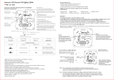
3.7 Connectors (hook-up diagram)

Bronkhorst®
Instruction Manual Vapor Delivery Module 9.17.079E14

Bronkhorst®
Instruction Manual Vapor Delivery Module9.17.079E 15
4Installation
4.1 Mounting
The mounting position of the equipment is upright. Please take attention:
·Avoid installation in close proximity of mechanic vibration and/or heat sources.
·Avoid contact between hot surfaces of the enclosure with electrical cables and fluid hoses/pipes.
·Ventilation requires a minimum distance of 100 mm space from each side to a wall.
·Make use of the protective earth pin (see Connectors (hook-up diagram), connector 3) for grounding the connected
tubing. Use an appropriate cable.
·Mount the equipment in such a way, that cables and mains switches can easily be reached and disconnected.
4.2 Fluid connections
For exact information on the fittings, please contact Swagelok for further instructions or documentation.
Please be aware when using Oxygen (O2) that the fittings mounted in the gas line should be absolutely oxygen clean.
4.3 Supply pressure
Do not apply pressure until electrical connections are made. When applying pressure to the system, make sure that the
pressure is increased gradually and avoid pressure shocks in the system.
4.4 Leak check
Check the fluid system for leaks before applying pressure, especially when using hazardous media (e.g. toxic or flammable).
4.5 Seals
Bronkhorst has gathered a material compatibility chart from a number of sources believed to be reliable. However, it is a
general guide only. Operating conditions may substantially change the accuracy of this guide. Therefore there is no liability
for damages accruing from the use of this guide. The customer’s application will demand its own specific design or test
evaluation for optimum reliability. So check order documentation if the used seals are correct for the process.

Bronkhorst®
Instruction Manual Vapor Delivery Module 9.17.079E16
4.6 Purging and filling
4.6.1 Starting up without using vacuum
4.6.1.1 Filling system
Procedure
Actions
A1
Purge all lines
·Close V2, V3 and V7
·Open V1, V4, V5 and V6
·Give setpoint 100% to MFC
·Give setpoint 0% to LFC
·Purge for a long time.
A2
Setup carrier gas supply
·Close V4
·Open V3
A3
Fill the system with liquid.
·Close V1
·Open V2 briefly; allow mixing valve VDM to fill.
·Wait until all gas bubbles left the system via Purge out
and V5, then close V5.
Make sure that the carrier gas is always flowing when
the liquid flow is on. It is preferred to always have gas
flowing in the carrier gas line when the system is filled
with liquid.
A4
The system is now ready for use.

Bronkhorst®
Instruction Manual Vapor Delivery Module9.17.079E 17
4.6.1.2 Starting process
Procedure
Actions
B1
Set the heater at right temperature
·Give set point to the heater; wait until the
temperature is stabilized
B2
Start gas flow
·Give setpoint to MFC
Make sure that the carrier gas is always flowing when
the liquid flow is on. Preferably, let always gas flow in
the carrier gas line when the system is filled with liquid.
B3
Start liquid flow
·Give setpoint LFC, wait until stabilization
Close supply pressure of the liquid vessel during the
process. The pressure controller of the inert gas supply
can influence the stability of the liquid flow controller.
B4
Connect process
·Open V7, close V6
4.6.1.3 Stopping process
Procedure
Actions
C1
Disconnect process
·Open V6, close V7
C2
Stop liquid flow
·Give setpoint = 0 to LFC
C3
Optional: Stop gas flow
·Give setpoint = 0 to MFC
Make sure that the carrier gas is always flowing when
the liquid flow is on. Preferably, let always gas flow in
the carrier gas line when the system is filled with liquid.
4.6.1.4 Leaving system overnight
Procedure
Actions
D1
Relieve the supply pressure from the liquid- and
carrier gas lines
·Close V2 and V3
4.6.1.5 Emptying and purging system
Procedure (1,2)
Actions
E1
Relieve the supply pressure from the liquid- and
carrier gas lines
·Close V2 and V3
E2
Purge liquid out of lines
·Open V1 and V5
E3
Purge lines with inert gas
·Open V4, V6
·Close V7
·Give setpoint to MFC
E4
Optional: purge with inert liquid
Connect inert liquid to inert gas supply, proceed from E2
E5
Optional: alter E3 and E4 for a few times
(1) If the liquid is reactive or aggressive, be sure to remove air (and water vapor) carefully, before introducing liquid in the
system.
(2) If the liquid is reactive, aggressive, poisonous, toxic, or flammable, beware that the system is purged fully (preferably with
inert liquid, E3, E4, E5) before opening the system.
·In case of non-pure liquids, place a filter upstream the liquid flow controller.
·Mount the VDM upright.

Bronkhorst®
Instruction Manual Vapor Delivery Module 9.17.079E18
4.6.2 Starting up using vacuum
4.6.2.1 Filling system
Procedure
Actions
A1
Evacuate the lines “Vacuum”
·Start pumps
A2
Evacuate all lines
·Close: V1, V2, V3, V4, and V6
·Make sure that “waste” and “process” are vacuum
·Connect inert gas on carrier gas inle.
·Open : V5 and V8
·Give setpoint to gas and liquid control (the control
valves of the LFC and MFC open)
·Pump for a long time
·Remark: if the system is not completely dry follow
procedure of E3, E4, (E5)
A3
Purge line between inert gas source and valve V1
·Open valve V1 briefly for some seconds.
A4
Purge line between process gas source and gas
MFC
·Give setpoint = 0 to LFM (mix valve closes)
·Open valve V3 briefly for some seconds
A5
Pump down liquid supply
·Open V2 for some time
·Close V2
A6
Setup carrier gas
·Close V8
·Open V3
A7
Fill the system with liquid
·Close V1
·Open B2 briefly; allow mixing valve VDM to fill
·Close V5
Make sure that the carrier gas is always flowing when
the liquid flow is on. Preferably, let always gas flow in
the carrier gas line when the system is filled with liquid.
A8
Optional: degassing mixing valve
·Open V5, a needle valve will be best, to avoid too
much liquid be pumped away
A9
The system is now ready for use
4.6.2.2 Starting process
Procedure
Actions
B1
Set the heater at right temperature
·Give setpoint to the heater, wait until temperature is
reached
B2
Start gas flow
·Give setpoint to MFC
Make sure that the carrier gas is always flowing when
the liquid flow is on. Preferably, let always gas flow in
the carrier gas line when the system is filled with liquid.
B3
Start liquid flow
·Give setpoint LFC, wait until stabilization
Close supply pressure of the liquid vessel during the
process. The pressure controller of the inert gas supply
can influence the stability of the liquid flow controller.
B4
Connect process
·Open V7, close V6

Bronkhorst®
Instruction Manual Vapor Delivery Module9.17.079E 19
4.6.2.3 Stopping process
Procedure
Actions
C1
Disconnect process
·Open V6, close V7
C2
Stop liquid flow
·Give setpoint = 0 to LFC
C3
Optional: Stop gas flow
·Give setpoint = 0 to MFC
Make sure that the carrier gas is always flowing when
the liquid flow is on. Preferably, let always gas flow in
the carrier gas line when the system is filled with liquid.
4.6.2.4 Leaving system overnight
Procedure
Actions
D1
Relieve the supply pressure from the liquid- and
carrier gas lines
·Close V2
·Open V8 for some seconds
4.6.2.5 Emptying and purging system
Procedure (1,2)
Actions
E1
Relieve the supply pressure from the liquid- and
carrier gas lines
·Close V2 and V3
E2
Purge liquid out of lines
·Open V1 and V4
E3
Purge lines with inert gas
·Open V4 and V6
·Close V7
·Give setpoint to MFC
E4
Evacuate liquid lines (cont.)
·Close V1
·Open V8
E5
Optional: repeat last two steps for a few times
(1) If the liquid is reactive or aggressive, be sure to remove air (and water vapor) carefully, before introducing liquid in the
system.
(2) If the liquid is reactive, aggressive, poisonous, toxic, or flammable, beware that the system is purged fully (preferably with
inert liquid, E3, E4, E5) before opening the system.
·In case of non-pure liquids, place a filter upstream the liquid flow controller.
·Mount the VDM upright.

Bronkhorst®
Instruction Manual Vapor Delivery Module 9.17.079E20
5Operation
5.1 Powering up
Before switching on the power, be sure that:
·System is checked for leakage of gases and liquids
·All connections have been made
·Flow-set points are zero
·No liquid has been spilled into the equipment
Switch on and then:
·Allow 30 minutes (from switching on) to warm up (common for thermal flow controllers)
·Wait until temperatures setpoints are reached. When the LED indicators turn blue, temperature
setpoints are reached.
·Make sure that the carrier gas is always flowing before the liquid flow setpoint is applied.
5.2 User interface
5.2.1 Buttons
The buttons have the following functions:
- Enter selected menu
- Enter edit mode
- Confirm selection/changes
- Menu selection up
- Select information field
- Next character in edit mode
- Up in table
- Menu selection down
- Select information field
- Previous character in edit mode
- Down in table
- Return to previous screen
- Undo, cancel and exit edit mode
- Switch content in the 'Custom readout 2' field
Top line
Custom readout 1
Measure readout
Custom readout 2
5.2.2 Display
The display is divided into 4 areas, ‘Measure readout’,
‘Custom readout 1’, ‘Custom readout 2’ and the 'Top line'.
The information in these areas can be configured by the
user.
If an area contains a parameter which can be set or reset
by the operator, you can press or to select this
parameter. Press to enter the edit mode or press to
return to the ‘Measure readout’ screen .
If ‘Custom readout 1’ is disabled, you can only
switch between ‘Measure readout’ and ‘Custom
readout 2’.
/