Page is loading ...

Assembly Instructions
IF2035-PROFINET
Intended Use
The IF2035-PROFINET interface module is designed for use in industrial and laboratory applications.
It is used to convert the internal MICRO-EPSILON sensor protocol (RS485, RS422) to Profinet.
The interface module must only be operated within the limits specified in the technical data.
The interface module must be used in such a way that no persons are endangered or machines and
other material goods are damaged in the event of malfunction or total failure of the sensor/controller.
Take additional precautions for safety and damage prevention in case of safety-related applications.
Warnings
Connect the power supply and the display/output device according to the safety regulations for
electrical equipment.
> Risk of injury
> Damage to or destruction of the interface module
The supply voltage must not exceed the specified limits.
> Damage to or destruction of the interface module
Avoid shocks and impacts to the interface module.
> Damage to or destruction of the interface module
Proper Environment
Protection class: IP 20
Operating temperature: 0 ... +50 °C (+32 ... 122 °F)
Storage temperature: -20 ... +70 °C (-4 ... +158 °F)
Humidity: 5 - 95% (non-condensing)
Ambient pressure: Atmospheric pressure
Connection Options
C-Box Analog
IFD242x, IFD246x
ILD1x20
ILD1750
ILD19x0
ILD2300
ILR2250
IMS54xx, IMS56xx
MFA-7/14/21/28
ODC2520
SC2471-x/RS422/OE
Sensor/
Controller
PC/SC2520-x
CAB-M12-8P-St-ge
PC2250-x
SC2471-x/RS422/OE
PC2300-x/OE
RS485 RS422
DT6120
INC5701
SCAC3/6
PCx/8-M12
Sensor/
Controller
PC1900-x/OE
MSC7xxx PC7400-6/4
DTD PC5/5-IWT
CableCable
Direct or PCF1420-x/I/U
PC1700-x/OE
Direct
The length of the cable between IF2035-PROFINET and sensor/controller is 10 m at most. Because of
the PCx/8-M12 cable, the sensor supply for INC5701 sensors is possible only via the IF2035-PROF-
INET.
Standard Cabeling
During cabling, channel 0 of the IO controller is connected to the input port of the first IO device
(slave device). The output port of the first slave device is connected to the input port of the next
slave device, etc. The output port of the last slave device and channel 1 of the master device remain
unused.
Adapter 1 Adapter 2 Adapter n
Scanner
Redundancy
You achieve greater failsafe network performance if you implement an additional redundant connec-
tion (MRP = Media Redundancy Protocol) between the output port of the last slave device and chan-
nel 1 of the IO controller. IF2030 can participate in an MRP ring as a client; however, it cannot manage
the ring. To achieve ring functionality, all participants must be configured as ring participants.
X9771467-A012103MSC
MICRO-EPSILON MESSTECHNIK GmbH & Co. KG
Koenigbacher Str. 15 • 94496 Ortenburg
e-mail [email protected]
www.micro-epsilon.com
Your local contact: www.micro-epsilon.com/contact/worldwide/
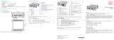
Installation and Assembly
i Ensure careful handling during installation and operation.
22.6
99
107
113.7 (4.476)
TS35
Top-hat rail
4.236 max
4.197 min
.904 max
.878 min
3.913 max
3.881 min
Dimensions in mm
(inches, rounded off)
Pin Assignment
Supply Voltage
The supply voltage is daisy-chained from the supply
port (terminal 1) to the sensor port (terminal 2), i.e., the
supply voltage must match that of the sensor. Positive
voltage must be between 9 V and 36 V.
Connect the inputs V+ and on terminal 1 to a
voltage supply. Maximum cable length 3 m.
MICRO-EPSILON recommends using the optionally
available power supply PS2020.
230 VAC PE
N L
Cable Termination at Interface
i Ensure correct cable termination for an RS485 bus or RS422 bus! The IF2035-PROFINET
works as a master for both interfaces; internally, a 120 Ohm terminating resistor has already
been permanently incorporated. The IF2035-PROFINET should be at the bus start.
A
B
IF2035
RS485
Slave n
Slave n-1
n = max. 16 Slaves
120
Ohm
120
Ohm
RS422
RX+
RX -
IF2035 Slave 1
120
Ohm
120
Ohm
TX -
TX+
120
Ohm
120
Ohm
A B S S
T RRT
M1M2V
M1M2V
Terminal 1 Terminal
Terminal 2 Terminal 4 Terminal 2 Terminal 4
V+ Supply voltage 1 T+ RS422 Tx+
Ground for supply voltage T- RS422 Tx-
M1 Multifunction input 1 R+ RS422 Rx+
M2 Multifunction input 2 R- RS422 Rx-
Terminal 1 connections daisy-chained Ground 2 e.g., for RS422 shield connection
Terminal 1 Terminal 3
V+ Supply voltage 1 A RS485 A
Ground for supply voltage B RS485 B
M1 Multifunction input 1 S+ Synchronization output +
M2 Multifunction input 2 S- Synchronization output -
Terminal 2 connections daisy-chained Ground 2 e.g., for RS485 shield connection
1) If the distance between IF2035-PROFINET and the
sensor/controller is long, a separate supply for the
sensor/controller may be advisable.
2) Internally connected to supply ground

Quick Guide
GSDML File
The GSDML file contains information about a PROFINET device. This file is needed for the
PROFINET controller and must be integrated into the corresponding configuration software.
The current version is available at:
https://www.micro-epsilon.de/download/software/IF2035-GSDML-XML.zip
Import the GSDML file. To do so, in the Extras > Manage device description
files (DDF) menu, select the path for the file <GSDML-V2.43-MICRO-EPSILON-IF-
2035PNET-xxx.xml>.
Click the Install button.
IP Address, Network Name
The IF2035-PROFINET has no IP address and no network name by default. These settings must be
made in the PLC programming environment (e.g. TIA Portal or PRONETA).
In program examples the parameters baud rate, input width, sensor interface, minimum cycle time
are set appropriately. The current version is available at:
https://www.micro-epsilon.de/download/software/IF203x-PNET-standard-example-library.zip
Example: Configuring the Sensor Interface
1
2
3
4
5
Module integration with the TIA Portal software
Parameter Section/Description
1 Number of data bytes, see Data Format section
2 Baud rate
3 Minimum cycle time, see Data Format section
4 Sensor interface, see Configuring the Sensor Interface section
5 Init CFG, see IP Address section, network name
i Please note the instructions for applying a project, see the Completion, Applying a Project sec-
tion.
Configuring the Sensor Interface
Only sensors (controllers) that support the ME sensor protocol can be connected via RS485/RS422,
see Connection Options section.
Protocol Sensor/controller
0: ME-Bus + RS485 DT6120
INC5701
MSC7401/MSC7x02/DTD
2: MEO-ASCII + RS422 C-Box analog
IFD242x/IFD246x
ILD1220/ILD1320/ILD1420/ ILD1750/ILD1900/ILD2300
IMS54xx/IMS56xx
MFA-7/14/21/28
ODC2250
3: MEO-ASCII + RS422 - 32 bit ILR2250, IMC5xx0
Baud Rate
The baud rate at the sensor/controller and in the hardware configuration of the IF2035-PROFINET
must match. There is no automatic baud rate matching between IF2035-EtherCAT and the connect-
ed sensor (controller). Details about the default baud rate can be found in the individual operating
instructions of the respective sensor/controller.
Data Format
All configuration parameters and data are transmitted from the IF2035 in Little Endian format. The
IF2035 converts a sensor-specific protocol into a uniform 4-byte data format.
No. of data bytes Sensor/controller Minimum Cycle Time
16 byte DT6120 0
ILD1220/ILD1320/ILD1420/ ILD1750/ILD1900/
ILD2300 0
ILR2250 50 ms
IMC5xx0 0
MSC7401/DTD 2 ms
ODC2520 0
32 byte C-Box analog 0
MSC7x02 2 ms
INC5701 0
IFC242x 0
You can find more information about the sensor in the operating instruc-
tions. They are available online at:
www.micro-epsilon.de/download/manuals/man--IF2035-PROFINET--en.pdf
Completion, Transferring a Project
After setting all parameters, the configuration must be transferred once to the module via the
Initial configuration sequence.
Proceed as follows:
Set the Init CFG (5) to Enabled.
Transfer the project to the controller and the IF2035/PROFINET
Set the Init CFG (5) to Disabled.
/