Page is loading ...

PC1700-X
ILD1750
PC2300-X/SUB-D + PC2300-0,5/Y
ILD2300
ODC2500
PS2020
230 VAC
PE
N L
PS2020
X = Cable length in m
SCD2500-X/RS422
PC/SC2520-3
ODC2520
CAB-M9-5P-St-ge; 2m-PVC-RS422 ACS7000
PC2300-X/OE
ILD2300
PCF1420-X/I
ILD1420
PCF1420-X/IF2008 ILD1420
IF2004/USB-Y
PC1700-X/IF2008 ILD1750
PC2300-X/IF2008 ILD2300
SCD2004-3/Trigger
PC/SC2520-3/IF2008 ODC2520
SCD2500-X/IF2008 ODC2500
SC2471-X/IF2008 IFC24x1, IFC2422
CAB-M9...RS422;Sub-D ACS7000
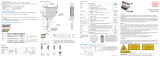
Fig. 1 Connections front side Fig. 2 Connections rear side
Connect the converter to a power supply, for example PS2020.
Connect the converter to a free USB interface to start the driver installation. You will find the driver on the delivered CD.
i
Use the optional available Y-adapter cable IF2008-Y when using 3 or 4 sensors on the 15-pin. Sub-D-connectors.
RS422 Connections to 6-pin. Terminal
Pin Assignment ILD1420
PCF1420-X/I
ILD1750
PC1700-X
ILD2300
PC2300/OE
PC2300-0,5/Y
ODC2520
PC/SC2520-x
ODC 2500
SCD2500-x/
RS422
ACS7000
CAB-M9-5P-
St-ge
Serial numbers up to 000253
1 Converter TxD- green gray blue
2 Converter TxD+ yellow yellow red
3 Converter RxD+ pink brown violet
4 Converter RxD- gray green black
Serial number from 000300
1 Converter TxD- yellow yellow red green green brown
2 Converter TxD+ green gray blue brown yellow white
3 Converter RxD+ gray green black gray white yellow
4 Converter RxD- pink brown violet yellow brown green
RS422 Connections to 15-pin. Sub-D, Sensor 1/2 and 3/4
Pin Assignment Pin Assignment
1 Sensor 1/3 Tx- 11 Sensor 2/4 Tx-
2 Sensor 1/3 Tx+ 12 Sensor 2/4 Tx+
3 Sensor 1/3 Rx- 13 Sensor 2/4 Rx-
4 Sensor 1/3 Rx+ 14 Sensor 2/4 Rx+
5 GND 15 GND
6 Sensor 1/3 TRG+ 8 Sensor 2/4 TRG+
7 Sensor 1/3 TRG- 9 Sensor 2/4 TRG-
10 +24 V
2
10 +24 V
2
2) Power supply +24 V via power connections, see Fig. 1.
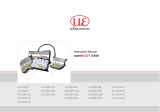
Assembly Instructions IF2004/USB
4-Channel RS422/USB Converter
Measurement assembly for sensors of ILD1420 / 1750 / 2300 - of confocalDT IFD2421 / 2422 / 2451 / 2461 / 2471 -
of optoCONTROL ODC2500 / 2520 / 2600 - of colorCONTROL ACS7000
Trigger Inputs
Pin 1 Trigger IN 1
1
2
7
6
5
4
3
Pin 2 Trigger IN 2
Pin 3 Trigger IN 3
Pin 4 Trigger IN 4
Pin 5 Trigger OUT 1
Pin 6 Trigger OUT 2
Pin 7 GND
7-pin. subminiature male cable connector,
Company Binder, series 712, view: solder pin side male
cable connector
Unpacking
1 Converter IF2004/USB
1 USB cable
1 CD with driver, instruction manual

*X9771304-A08*
X9771304-A081049SWE
MICRO-EPSILON MESSTECHNIK
GmbH & Co. KG
Königbacher Str. 15 · 94496 Ortenburg
www.micro-epsilon.com
Installation USB Driver
Insert the installation CD-ROM in the CD-ROM-drive.
Connect the sensor to the USB converter. Connect the USB
converter to a free USB port on a PC / notebook.
Connect the converter to a power supply.
The driver installation starts automatically. Depending on the
operating system the latest driver from the Internet or driver CD is
used.
Windows 7
If you use a PC with Internet access, connect the converter to a
free USB port. Windows 7 looks automatically for the latest driver
version and installs the driver.
Manual Installation of Driver
You can also install the driver manually if the driver is not installed
automatically.
Install the driver as follows:
Load the CD in to the CD-ROM drives.
Connect the sensor/controller with the USB converter.
Connect the USB converter cable with a free USB port.
Connect the converter with a power supply.
Start the device manger, see Fig. 3, menu Start > Con-
trol Panel > Device Manager.
Right-click the entry USB Serial Port and choose Up-
date Driver Software ...
Fig. 3 View on Device Manager
Choose the path for the driver by means of Browse ...
Click on the button Next.
The routine now starts the installation of the driver.
Click on the button Close, to finish installation.
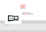
Supply Voltage
Nominal value: 24 V DC
Only turn on the power supply after wiring has been completed.
Connect the 24VDC and GND inputs at the converter with a
24 V voltage supply.
24 V DC
i
Use the supply voltage for
measurement instruments
only and not for drive
units or similar sources of
pulse interference at the
same time. MICRO-EPSI-
LON recommends using
an optional available
power supply unit PS2020
for the converter.
Fig. 4 Connector power supply
Trigger Inputs
Pin Belegung
1 Trigger IN 1
1
2
7
6
5
4
3
2 Trigger IN 2
3 Trigger IN 3
4 Trigger IN 4
5 Trigger OUT 1
6 Trigger OUT 2
7 GND
7-pin. subminiature cable connector, Fa. Binder, series 712,
view on solder pin side
/