Page is loading ...

NYC-LC1
Page 1 of 4
Beghelli U.S.A., 3810 Executive Way, Miramar, Florida, Tel: (954) 442-6600
04/25/22
When using electrical equipment, basic safety precautions should always be followed including:
1. Disconnect power before performing work on electrical equipment.
2. Do not use outdoors.
3. Do not let power cords touch hot surfaces and do not mount near gas or electric heaters.
4. Use caution when servicing batteries. Battery acid can cause burns to skin and eyes. If acid is
spilled on skin or eyes, flush with fresh water and contact a physician immediately.
5. Equipment should be mounted in locations and at heights where unauthorized personnel will
not readily subject it to tampering.
6. The use of accessory equipment not recommended by Beghelli Inc., may cause an unsafe
condition, and will void the unit’s warranty.
7. Do not use this equipment for other than its intended purpose.
8. Servicing of this equipment should be performed by a qualified service personnel.
9. Disconnect AC power supply before servicing.
10. Unpack and check for concealed transit damage.
11. Report any transit damage to delivering carrier and file claim.
12. SAVE THESE INSTRUCTIONS!
Fixtures must be wired in accordance with National electrical code and all applicable local codes.
Proper grounding is required for safety.
This product must be installed in accordance with the applicable installation code by a qualified
electrician who is familiar with the construction and operation of the product and the hazards
involved.
IMPORTANT SAFEGUARDS
Read & Follow All Safety Instructions
INSTALLATION INSTRUCTIONS

NYC-LC1
Page 2 of 4
Beghelli U.S.A., 3810 Executive Way, Miramar, Florida, Tel: (954) 442-6600
04/25/22
WARNING: MAKE SURE THAT POWER IS OFF BEFORE MAKING ANY ELECTRICAL
CONNECTIONS!
WIRING INSTRUCTIONS
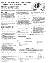
1. Make sure that all wires are carefully tucked away from the cavity behind the plastic inset.
2. Plug the mating connector of the battery to the PC board.
3. Unused wires must be capped using enclosed wire nuts.
WHITE:
BLACK:
RED/ORANGE:
GREEN:
Return for 120VAC or 277VAC wiring
Hot lead for 120VAC wiring
Hot lead for 277VAC wiring
Equipment ground
AC Only Battery Backup/SDT Dual Circuit Unit
FLUSH MOUNTING
1. Remove face plate cover by pulling equally at the outer rim of the
face plate on two opposite sides. Remove ground wire from face
plate (Figure F).
2. Remove the center KO and also required KOs that will match the
junction box.
3. Route the wires through the center knock-out. Make electrical
connections inside the junction box as described in the electrical
connection section of this instruction sheet. Push wires back
against the back of the sign to minimize any of the wires
interfering with the illumination of the letters.
4. Now mount the sign to the J-Box.
5. Remove the proper chevron(s) from the EXIT legend(s) if
necessary. Re-attach the ground wire to the face plate (Figure F).
6. Attach battery jumper wire (where applicable) to PC board and
replace face plate back on unit to complete installation.
FIGURE F

NYC-LC1
Page 3 of 4
Beghelli U.S.A., 3810 Executive Way, Miramar, Florida, Tel: (954) 442-6600
04/25/22
CANOPY MOUNTING (Top or Side-end mount)
1. Remove face plate cover by pulling equally at the outer rim of the
face plate on two opposite sides. Remove ground wire from face
plate (Figure F).
2. Pop out the plastic mounting hole cover on the top or the side of
the sign. Place one of the nuts from threaded stem rod in the slot
inside the housing just inside of the unit (Figure A).
3. Feed the AC supply and ground wire through the nut & hole and
out of the sign housing (Figure B).
4. Secure the canopy J-Box cover to the mount area of the exit sign
by inserting it and shifting it over to align the hole.
5. Feed AC supply wires and ground wire through threaded stem
and screw stem into nut inside unit. Screw the remaining nut
for the threaded stem onto the stem and tighten securely to
complete the mounting of the canopy to the exit sign (Figure C).
6. Determine the position the exit needs to be mounted (the way
the face needs to be pointed). Use the included round J-Box
mounting plate and small #8-32 screws to accomplish (Figure D).
7. Make connection with the AC supply wires in the J-Box as
described in the electrical connection section of this instruction.
8. Now mount the sign to the J-Box plate with the (2) #8-32 screws
provided and tighten securely (Figure E).
9. Remove the proper chevron(s) from the EXIT legend(s) if
necessary. Re-attach the ground wire to the face plate (Figure F).
10. Attach battery jumper wire (where applicable) to PC board and
replace face plate back on unit to complete installation.
FIGURE A
FIGURE B
FIGURE CFIGURE D
FIGURE E
FIGURE F

NYC-LC1
Page 4 of 4
Beghelli U.S.A., 3810 Executive Way, Miramar, Florida, Tel: (954) 442-6600
04/25/22
SELF-DIAGNOSTICS TEST (Autotest)
1. Introduction
Once the unit is properly installed according to the Installation instruction sheet and AC power is supplied, the
EXIT will come ON. The dual-color LED indicator will also come ON, automatically initiating the self-diagnostic
test function. The LED indicator points out the current unit status. A STEADY GREEN on the LED indicator a
normal service; BLINKING GREEN indicates that the unit is in testing mode; GREEN/RED FLASHING indicates
that the battery is charging; RED (STEADY and BLINKING) would indicate a fault or a service alert. Refer to
section 3 – Fault Indication for more details. The LED indicator would be OFF when the unit is in Emergency
mode.
3. Fault Indication
FAULT DESCRIPTION LED INDICATION
Battery disconnection STEADY Red
Battery recharge failure FLASHING Red
Battery failure Red BLINKING ‘2’ times
LED failure Red BLINKING ‘3’ times
* A battery recharge failure is more likely seen after a monthly or annual auto-discharge.
** A battery failure is more likely seen when the unit goes into a monthly/annual discharge test and/or fails to
run the LED strip for the designated amount of time in Test/Emergency mode.
4. Manual Testing
This unit also provides for manual testing by pushing the test switch in a specific pattern. The different patterns
and the resulting tests are listed in the table below.
ACTION REACTION AND LED INDICATION
Push test button Once (within 2 seconds) 30-second test: FLASHING Green
Push test button Twice (within 2 seconds) 30-minute test; Green BLINKING ‘2’ times
Push test button Thrice (within 2 seconds) 90-minute test; Green BLINKING ‘3’ times
Push and Hold test button (for 3-5 seconds) Interruption
Push and Hold test button (for more than 6 seconds) System reset
2. Self-Diagnostic Service
The self-diagnostic function is factory preset without any field adjustment. The automatic self-diagnostic feature
serves the following tests:
a. On-line real time monitoring of battery and LED(s): Identifies battery charging, disconnection and failure
along with LED failures.
b. Self-testing and a 30-second discharge once every 30 days (conforming to NFPA code requirements), after
AC power has been supplied for a minimum of 24 hours.
c. Self-testing and a 30-minute discharge once every 180 days, after AC power has been supplied for a
minimum of 24 hours.
d. Self-testing and a 90-minute discharge once every 365 days (conforming to NFPA code requirements), after
AC power has been supplied for a minimum of 24 hours
5. Operation
During an electrical power failure, the LED strip will transfer into Emergency mode and stay LIT for a minimum
of 90 minutes. To test this unit, the battery needs to be charged initially for 2 hours before depressing the test
switch (to do manual test). On pressing the test switch, the LED strip will transfer to a SIMULATED emergency
mode with the LED indicator FLASHING/BLINKING green. The LEDs will turn OFF after 30 seconds/30
minutes/90 minutes respectively.
/