Page is loading ...

TM
1
Universal Power Supply
Installation Instructions
Document Number 9000-A2-GN21-00
September 1997
The universal power supply is only installed on a 1-slot access unit, and is intended for
international markets.
Package Contents
The shipping box contains a desktop (in-line) power transformer, with an attached cord
and ferrite choke, for connecting to the access unit; no other items are included. You
must purchase the power cord separately.
Before You Begin
Make sure you have:
A 1-slot assembled access unit.
A dedicated, grounded power outlet that is protected by a circuit breaker within
6 feet of the access unit.
A clean, well-lit, and ventilated site that is free from environmental extremes.
One or two feet of clearance for cable connections.
A power cord (ordered separately).

2
Refer to the following table to verify that you have the appropriate power cord for the
wall-plug standard in your country.
Country Plug Standard Part Number Power Cord Description
United
Kingdom
BS1363 125-0075-0031 IEC 320-to-BS1363 – 2.5M
Continental
Europe, the
Netherlands
and India
CEE-7/7 125-0074-0031 IEC 320-to-CEE-7/7 – 2M
South Korea NEMA 5-15P 125-0007-0031 IEC 320-to-NEMA 5-15P –
2.3M
Call your sales or service representative to order the appropriate cable.
Technical Specifications
Specification Criteria
Power
Input
Output
100 – 240 Vac, 50/60 Hz, 0.7A
12 Vdc, 2.5A, 1.0A minimum
Power Consumption and Dissipation 9.7 watts, 0.143 amps at 120 Vac
9.6 watts, 0.125 amps at 240 Vac

3
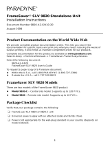
Installing the Power Supply and Cord
1. Insert the power supply’s 4-prong plug into the POWER jack.
When inserting the plug at the rear of the access unit, align the plug with the notch
above the POWER jack. Make sure the locking tab snaps securely into the jack.
97-15452
POWER
PORT 1
PORT 2
COM NET BKP
Power Supply/Cord
Grounded
Power Outlet
DSX-1
Locking
Tab
POWER
COM
OK
ALM
2. Insert the 3-prong socket end of the power cord into the power supply’s receptacle.
3. Insert the plug end of the power cord into the grounded power outlet.
Verification Check
Did any LEDs light?
If yes, the access unit has power and is operational.
If no, refer to
Troubleshooting
on the next page.

4
Troubleshooting
Symptom Possible Cause Solutions
No power, or none of the
system LEDs are lit.
Power cord is not securely
plugged into the wall power
outlet or the universal
power supply.
Check that the power cord
is securely attached at both
ends.
Universal power supply is
not securely connected to
the power cord, or to the
rear panel connector.
Check that the universal
power supply is securely
attached at both ends.
Wall receptacle has no
power.
1. Check the wall
receptacle power by
plugging in some
equipment that is known
to be working.
2. Check the circuit
breaker.
LED is burned out. Run the Lamp Test. If the
LED in question does not
flash with the other LEDs:
1. Check the async
terminal-to-COM port
connection.
2. Contact your sales or
service representative.
Power supply is defective. Contact your sales or
service representative.
Refer to Chapter 5,
Maintenance and Troubleshooting
, in the
FrameSaver 9620
User’s Guide
(Document No. 9621-A2-GB20) or Chapter 5,
Troubleshooting and
Maintenance,
in the
Frame Relay Access Unit, Model 9620/9621, Technical Reference
(Document No. 9621-A2-GH30) for additional troubleshooting information.
Removing a Power Cord
When disconnecting a power cord/supply from an installed access unit:
1. Disconnect the power cord plug from the power outlet first.
2. Then, depress the locking tab of the 4-prong plug from the rear of the access unit to
disconnect the power supply.
*9000–A2–GN21–00*
/