Page is loading ...

TM
1
FrameSaver SLV NNI
Installation Instructions
Document Number 9024-A2-GN11-01
September 1998
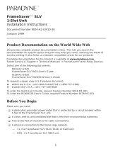
If you ordered a wall mounting kit (Feature No. 9001-F1-891) for your 1-slot
FrameSaver SLV (service level verifier) NNI (network-to-network interface) unit, install
the wall mounting before you start installing the unit.
Contact your sales representative to order this feature.
Before You Begin
Make sure you have:
A dedicated, grounded power outlet that is protected by a circuit breaker within
6 feet of the FrameSaver SLV NNI unit.
A clean, well-lit, and ventilated site that is free from environmental extremes.
One to two feet of clearance for cable connections.
A physical T1 connection to the frame relay network.
An async (asynchronous) terminal or PC (personal computer) to set up the
FrameSaver NNI unit.
Node IP Addresses and Subnet Masks. See your network administrator for this
information.
The DLCI (data link connection identifier) for each end of the PVC (permanent
virtual circuit), provided when the frame relay service was purchased.
A frame relay switch that supports V.35.

2
Worksheets
It is recommended that you complete configuration worksheets before you begin, with
changes from the default (factory-set) settings and information to be entered clearly
marked (e.g., the node’s IP address). Having completed worksheets before installation
is begun speeds setup time.
Worksheets are provided in Appendix B of the
FrameSaver SLV NNI Supplement
.
NOTE:
It is important that you follow the instructions for installing the FrameSaver NNI unit
as they are presented if you are to have a quick and trouble-free installation. Do
not install your cables until instructed to do so.
Package Checklist
Verify that your package contains the following:
1-Slot FrameSaver SLV NNI unit
Power cord with desktop 120 Vac power transformer
Universal power supply with an attached cable and ferrite choke
RJ48C (T1) modular cable for U.S. network access (20 feet – 6.1 meters)
FrameSaver SLV
9x24
User’s Guide
(Document No. 9024-A2-GB20)
The User’s Guide and the Adobe Acrobat Reader are provided on diskettes. A PC
running Microsoft Windows 3.1 or higher is required to view or print the document.
FrameSaver SLV NNI Supplement
(Document No. 9024-A2-GB40)
Warranty card
Training reply card
Additional cables may need to be ordered. See
Cables You May Need to Order
on
page 3 when ordering cables.

3
Cables You May Need to Order
FrameSaver SLV NNI units have native interfaces so cables can be purchased
anywhere, with the following exceptions.
If connecting to a . . . Order a . . .
Model/Feature/
Part Number
T1 Line interface/connector
(
For use in Canada
)
T1 line interface cable,
RJ48C-to-CA81A
3100-F1-510
LAN Customer converter with a DB25
plug on one end and an 8-pin
modular jack on the other end, with
a custom 8-conductor cable and
LAN adapter
3100-F2-910
External Device
(e.g., a modem)
Standard EIA-232-D crossover
cable
9008-F1-550
Contact your sales representative to order cables.
Safety Instructions
Please read the EMI Warnings and Important Safety Instructions in the
FrameSaver
SLV 9x24 User’s Guide
.

4
Installing the Power Supply and Cord
1. Insert the 4-prong plug into the POWER jack.
When inserting the plug at the rear of the FrameSaver NNI unit, align the plug with
the notch above the POWER jack. Make sure the locking tab snaps securely into
the jack.
POWER
COM
NETWORK
DSX-1
98-16122
Power Supply/Cord
Grounded
Power Outlet
Locking
Ta b
POWER
COM
OK
ALM
2. Insert the socket end of the power cord into the power supply’s receptacle.
3. Plug the power cord into the grounded power outlet.
Verification Check:
Did any LEDs light?
If yes, the FrameSaver NNI unit has power and is operational.
If no, refer to
Troubleshooting Power and COM Port Connections
on page 6.

5
Connecting the COM Port to an Async Terminal
The FrameSaver NNI unit must first be directly connected to a VT100-compatible
terminal, or a PC or async terminal providing VT100 terminal emulation to set up
access and management of the unit.
1. Configure the async or VT100-compatible terminal to be compatible with the
FrameSaver NNI unit:
— COM Port in use by your PC: COM1 or COM2.
— COM Port Baud Rate set to 19.2 kbps.
— Character length set to 8 data bits.
— Parity set to none.
— Stop bit set to 1.
— Flow Control set to None.
2. Insert the DB25 end of the EIA-232 cable into the FrameSaver NNI unit’s COM
port.
98-15824
POWER
COM
NETWORK
DSX-1
To Connect to a PC
or Async Terminal
COM
Port
(FrameSaver 9124
Shown)
3. Insert the other end of the cable into the VT100-compatible terminal.
4. Tighten the screws on each side of the connector to secure them.
5. Press Enter on the keyboard (or Return, depending upon your keyboard) to display
the Main Menu.
Verification Check:
Did the Main Menu appear?
If yes, you are ready to continue with the installation.
If no,
— Recheck terminal and FrameSaver NNI unit compatibility (see settings in
Step 1).
— Did you press the Enter key on your keyboard?
See
Troubleshooting Power and COM Port Connections
on page 6 for other
possible causes. See
Chapter 13,
Troubleshooting
, in the User’s Guide for
additional explanations.

6
Troubleshooting Power and COM Port Connections
Symptom Possible Cause Solutions
No power, or none
of the system LEDs
are lit.
Power cord is not
securely plugged into the
wall power outlet or the
universal power supply.
Check that the power cord is
securely attached at both ends.
Wall receptacle has no
power.
1. Check the wall receptacle power
by plugging in some equipment
that is known to be working.
2. Check the circuit breaker.
Power supply is
defective.
Contact your sales or service
representative for replacement of
the power supply.
An LED is not lit. LED is burned out. Run the Lamp Test. If the LED in
question does not flash with the
other LEDs, contact your sales or
service representative.
Power-Up Self-Test
fails. The Alarm
LED is on after
power-up, but the
OK LED is not.
The FrameSaver NNI
unit has detected an
internal hardware failure.
1. Reset the FrameSaver NNI unit
and try again.
2. Contact your service
representative.
Cannot access the
FrameSaver NNI
unit or the user
interface.
Login or password is
incorrect, COM port is
misconfigured, or access
to the FrameSaver NNI
unit is misconfigured.
1. Reset the FrameSaver NNI unit
(see Chapter 12,
Operation and
Maintenance
, of the User’s
Guide).
2. Contact your service
representative.

7
A Quick Guide to Configuration
The FrameSaver NNI unit should operate using the default (factory-set) configuration
options, with exception to the changes specified in these installation instructions. Refer
to the following table for help navigating the menus.
Press the . . . To . . .
Esc key Go back one screen or menu level. To see a visual
representation of the menu levels, see Menu Hierarchy in
the
FrameSaver SLV NNI Supplement.
Tab key, or
Up (↑) and
Down (↓) arrow keys
Move the cursor from one menu item to the next.
Enter or Return key Complete the menu or option selection.
Spacebar Display the next available setting when changing a
configuration option. All the available settings for an
option appears at the bottom of the screen.
As an example, follow these steps to go to the Configuration Edit/Display menu so you
can start setting up the unit:
1. From the Main Menu, press the down arrow or Tab key twice so the cursor is on
Configuration.
2. Press Enter to display the Configuration menu. The Load Configuration From
menu appears.
3. Press Enter to select Current Configuration, where the cursor is already
positioned. The Configuration Edit/Display menu appears.
This sequence of steps would be shown as the menu selection sequence:
Main Menu
→
Configuration
→
Load Configuration From:
→
Current Configuration
In the sections that follow, only the minimum option changes required are included so
you will have a quick and trouble-free installation.
In addition, each section identifies the worksheet you would be using if you were
provided a specified configuration, or when changing or recording configuration
changes from the default settings.*
*Worksheets are provided in Appendix B,
Configuration Worksheets
, of the NNI Supplement.

8
Installing and Setting Up the FrameSaver NNI
To complete the installation, you must:
Configure SNMP management.
Connect to the network.
Configure SNMP trap managers.
Configure a Management PVC to the NOC
Connect to the IEC/IXC.
NOTES:
Follow these instructions as they are presented. Installation time will be increased
if you connect the cables first.
Even though a DSX-1 interface is provided, it is not used in this release.
Verifying that Self-Test Passed
Before starting to configure the FrameSaver NNI unit, confirm that the unit passed the
self-test.
1. Follow this menu selection sequence from the Main Menu, pressing Enter after
each selection:
Main Menu
→
Status
→
System and Test Status
2. Check the Self-Test Results column (in the center of the System and Test Status
screen).
— If Passed appears, the FrameSaver NNI unit successfully completed the
self-test.
— If any failure messages appear, reset the unit by disconnecting, then
reconnecting the power cord. The unit will perform the self-test again. If the
failure reappears, call your service representative for assistance. You may
need to return the unit to the factory.

9
Setting Up SNMP Management
Worksheet:
Communication Protocol Options, then
Worksheet:
General SNMP Management Options
See
Configuring the Communication Protocol
and
Configuring SNMP Management
in Chapter 9,
Configuration Options
, of the User’s Guide to read about the configuration
options identified in the following procedure.
To set up SNMP management:
1. Select Communication Protocol configuration options from the Configuration
Edit/Display menu.
Configuration
→
Current Configuration
→
Management and Communication
→
Communication Protocol
2. Minimally, enter the following options:
— Node IP Address
— Node Subnet Mask
3. Press Esc once to return to the Management and Communication menu.
4. Select General SNMP Management and press Enter.
5. Minimally, set Name 1 Access to Read/Write.
6. Press Ctrl-a to move the cursor to the bottom of the screen, type s (S
ave), and
press Enter. The Save Configuration To: prompt appears.
7. Select Current Configuration and press Enter.
8. Press Esc three times to return to the Main Menu.

10
Connecting to the Network
1. Insert the 8-pin connector of the RJ48C network cable into the network interface.
2. Insert the other end of the cable into the RJ48C (T1) modular jack.
POWER
COM
NETWORK
DSX-1
98-1612
0
RJ48C
Jack
NOTE:
After connecting the network cable, wait a few minutes to allow
Auto-Configuration time to discover DLCIs.
Verification Check:
1. Check the Network LEDs. Is the Sig (signal) LED on, and are the OOF (out of
frame) and ALM (alarm) LEDs off?
— If yes, the network interface is set up correctly and is operational.
— If no, check that both ends of the network cable are properly seated.
2. Check Health and Status messages in the left column of the System and Test
Status screen to see the LMI status, to verify that LMI is up.
Main Menu
→
Status
→
System and Test Status
— If LMI Down, Network appears for more than three minutes, or if any other
network-related status message appears, refer to the status information in
Chapter 11,
Displaying System Information
, of the User’s Guide for possible
reasons for the messages and what can be done to resolve the problem.
Proceed to
Entering Trap Managers
on page 11.

11
Entering Trap Managers
Worksheet:
SNMP Traps Options
Now that the FrameSaver NNI unit is connected to the network, SNMP Trap Managers
can be configured.
To enter SNMP managers:
1. Select SNMP Traps configuration options.
Main Menu
→
Configuration
→
Current Configuration
→
Management and Communication
→
SNMP Traps
2. Minimally, enter at least one trap manager – the central site’s NMS trap manager:
— SNMP Traps set to Enable
— Number of Trap Managers
— NMS
n
IP Address (
n
being the first, second, third, etc. trap manager entered)
3. Press Ctrl-a to move the cursor to the bottom of the screen.
4. Type s (S
ave) and press Enter. The Save Configuration To: prompt appears.
5. Select Current Configuration and press Enter.
6. Press Esc three times to return to the Main Menu.
Helpful Hint:
You can press Ctrl-a, type m and press Enter to return to the M
ain Menu, or
you can press the Esc key until the Main Menu appears.
Proceed to
Setting Up a Management PVC to the NOC
on page 12.

12
Setting Up a Management PVC to the NOC
Management between the FrameSaver NNI unit and the service provider’s network
operations or control center (NOC or NCC) needs to be set up. A non-multiplexed DLCI
must be configured to carry management data between the FrameSaver NNI unit and
the NOC console.
To set up NOC management:
1. Select DLCI Records on the network interface:
Configuration Edit/Display
→
Network
→
DLCI Records
2. Type o (Modify) and press Enter. The Modify DLCI Record for DLCI Number?
prompt will appear.
3. Select the DLCI that will be used
by pressing the spacebar until the correct DLCI
number appears, then press Enter.
4. With the cursor on the DLCI Type field, press the spacebar to change the DLCI
Type from Multiplexed to Standard.
The Delete EDLCI Connections and Make it a Mgmt Only PVC? prompt
appears.
5. Type y for yes and press Enter.
PVC connections for the selected DLCI are broken, the Port-1 DLCI mapped to
this network DLCI and the embedded management DLCI (EDLCI) are deleted, and
the selected DLCI will be reconfigured as a management PVC.
Proceed to
Verifying the End-to-End Path
on page 13.

13
Verifying the End-to-End Path
After installation of an FrameSaver NNI unit, run an IP Ping test to ping the NMS at the
central site and verify that the entire path from the remote unit to the NMS is
functioning. To run the IP Ping test, NMS trap managers must have been configured for
the remote unit. One of those trap managers must be the NOC NMS.
If trap managers were not configured, proceed to
Troubleshooting the Network
Connection
on page 14 and run a Connectivity test.
1. Select the IP Ping test.
Main Menu
→
Test
→
IP Ping
2. Enter the IP Address of the device being pinged, then select Start.
NOTE:
When running tests, the cursor is positioned over the Start command.
Press Enter to start the test. Stop is displayed while the test is running.
Press Enter again to issue the Stop command.
— While the test is running, In Progress . . . is displayed in the Status field.
— When the test is finished, Alive. Latency =
nn
ms should appear as the
Status (
nn
being the amount of time the test took in milliseconds).
If any other message is displayed, additional testing will be required. See
Device
Messages
in Chapter 11,
Displaying System Information
, for information about IP
Ping-related messages.
Proceed to
Connecting to the IEC/IXC
on page 15.

14
Troubleshooting the Network Connection
1. Check the Network LMI Reported DLCIs screen to verify that the DLCI status
is Active.
Main Menu
→
Status
→
LMI Reported DLCIs
2. If two FrameSaver NNI units are located in your network, run a Connectivity test
between them.
Main Menu
→
Test
→
Network PVC Tests
→
Interior Connectivity
— If RndTrip Time (ms) appears, along with the number of milliseconds it took
to receive a response, the FrameSaver NNI unit at the other end is connected
and operational. Go to Step 3.
— If a response is not received within 5 seconds and No Response is reported,
refer to
Frame Relay PVC Problems
in Chapter 13,
Troubleshooting
, of the
User’s Guide.
3. Put one FrameSaver NNI unit into PVC Loopback, taking frames from the PVC
and looping them back.
Main Menu
→
Test
→
Network PVC Tests
→
Interior PVC Loopback
4. On the other FrameSaver NNI unit, send a pattern over the network interface and
monitor it.
Main Menu
→
Test
→
Network PVC Tests
→
Interior Send Pattern
→
Start
Interior Monitor Pattern
→
Start
— If there are few or no errors, the unit at the remote end is connected and
operational.
— If 5 packets out of 25 are missing or out of sequence and Out of Sync is
reported, refer to the
Device Messages
in Chapter 13,
Troubleshooting
, of the
User’s Guide for additional information.
See Chapter 11,
Displaying System Information
, of the User’s Guide for additional
message information. See Chapter 13 of the User’s Guide and Chapter 4 of the
NNI Supplement,
Troubleshooting
, for additional troubleshooting information.
Proceed to
Connecting to the IEC/IXC
on page 15.

15
Connecting to the IEC/IXC
1. Connect one end of the V.35 cable to Port 1.
2. Plug the other end of the cable into the IEC/IXC equipment.
3. Tighten the screws on each side of the connector to secure it.
POWER
COM
NETWORK
DSX-1
98-16121
IEC/IXC
Verification Check:
1. Is the Port OK LED on?
— If yes, the port is set up correctly and is operational.
— If no, check that both ends of the V.35 cable are properly seated and secured.
2. Check Health and Status messages in the left column of the System and Test
Status screen for messages.
Main Menu
→
Status
→
System and Test Status
— If System Operational appears, the Port-1 interface is set up correctly and
is operational.
— If System Operational does not appear, refer to the status information in
Chapter 11,
Displaying System Information
, of the User’s Guide.
NOTE:
When any error conditions are detected, a status message will appear along
the bottom right corner of the screen.

16
Check that Data is Being Received
1. Press Esc until you return to the Main Menu.
2. Select Performance Statistics, and select an interface’s frame relay statistics
(e.g., Network Frame Relay).
Main Menu
→
Status
→
Performance Statistics
→
Network Frame Relay
Reminder:
You can save keystrokes by using the up (↑ ) and down (↓) keys to scroll
through menu selections on the screen, from first-to-last menu selections, or
last-to-first.
3. Verify that the Frames Received and Characters Received counts under the
Frame Relay Link statistics are incrementing, and there are no errors under the
Frame Relay LMI statistics. Type r for R
efresh and press Enter to update the
counts that are displayed.
— If data is being received, the counters increment when the screens is
R
efreshed.
— If data is not being received, recheck the cable connections and replace or
repair a damaged cable. Recheck LMI status; you may need to contact your
service provider. Next, check SLV statistics.
4. Repeat steps 2 and 3 for the other interface (e.g., Port-1 Frame Relay).
See Chapter 11,
Displaying System Information
, of the User’s Guide for additional
status information. See Chapter 13,
Troubleshooting
, for additional troubleshooting
information.

17
Check FrameSaver NNI Connections
Check the SLV statistics to verify that the FrameSaver NNI unit is keeping statistics
between itself and another FrameSaver NNI unit, and between itself and the endpoint
unit.
1. Press Esc to return to the Performance Statistics menu.
2. Select Port-1 SLV, and verify that the two FrameSaver NNI units on each side of
the IEC/IXC are communicating and collecting data.
The Interior column should show the other FrameSaver NNI unit’s DLCI number
and IP address, and statistics should be showing a count instead of Unknown.
— If yes, both FrameSaver NNI units are installed and operational.
— If no, check that FrameSaver NNI unit at the other end is installed.
The Exterior column, for DLCIs that terminate in the FrameSaver NNI unit, should
show the endpoint unit’s DLCI number and IP address, and statistics should be
showing a count instead of Unknown.
— If yes, the FrameSaver NNI and endpoint units are set up correctly and are
operational.
— If no, recheck the cable connections, and replace or repair a damaged cable.
Check that the endpoint unit is installed.
3. Press the spacebar to cycle through the DLCIs passing through the FrameSaver
NNI unit. All the appropriate DLCIs should appear at the bottom of the screen and
in the Far End DLCI field. Do this for both the Interior and Exterior statistics.
— If yes, the units and their DLCIs are operational.
— If no, check the DLCI’s status.
See Chapter 11,
Displaying System Information
, of the User’s Guide for additional
status information. See Chapter 4,
Troubleshooting
, of the NNI Supplement for
additional troubleshooting information.
Check PVC Connections
Check PVC connections to verify that all PVCs, including management PVCs, are
configured, and to see whether the PVC is active or not.
1. Press Esc twice to return to the Status menu.
2. Verify that each PVC is active.
— If active, the FrameSaver NNI unit should be passing data.
— If not active, no data traffic can be carried by the PVC. If the PVC is configured
correctly, the circuit may be down.
See Chapter 11,
Displaying System Information
, of the User’s Guide for additional
status information. See Chapter 13,
Troubleshooting
, for additional troubleshooting
information.

18
Technical Specifications
Specification Criteria
Weight 2.59 lbs. (1.18 kg)
Power Consumption
and Dissipation
Built-in power cord
Power consumption
Normal service
voltage ranges
120 Vac power supply:
NEMA 5-15P plug
9.5 watts, 0.140 mA at 120 Vac
Average power 9.5 watts
120 Vac12 Vac, 60 Hz 3
Physical Environment
Operating temperature
Storage temperature
Relative humidity
Shock and vibration
32°F to 122°F (0°C to 50°C)
–4°F to 158°F (–20°C to 70°C)
5% to 85% (noncondensing)
Withstands normal shipping and handling
Approvals
FCC Part 15
FCC Part 68
Industry Canada
Safety
Class A digital device
Refer to the equipment’s label for the
Registration Number.
Refer to the equipment’s label for the
Certification Number.
Refer to the equipment’s label for safety
information.
COM Port/Interface –
Communications/Management
Standard
Data rates
25-position (DB25) connector
EIA-232/ITU, V.24 (ISO 2110)
9.6, 14.4, 19.2, 28.8, 38.4, 57.6, and 115.2 kbps

19
Specification Criteria
T1 Network Interface
Data rates
Services supported
Physical interface (USA)
Physical interface (Canada)
Framing format
Coding format
Line Build-Out (LBO)
ANSI PRM
Bit stuffing
Yellow alarm generation
8-position modular unkeyed USOC jack
Up to 1.536 Mbps
Fractional T1 service, frame relay service
RJ48C
CA81A using adapter cable
D4, ESF
AMI, B8ZS
0.0 dB, –7.5 dB, –15 dB, –22.5 dB
Selectable
FCC Part 68, AT&T TR 62411
Selectable
Port 1 –
DTE Synchronous Data Ports
Standard
Data rates
34-position V.35 connector
V.35/ITU (ISO 2593)
All fractional T1 rates; automatically set to the
network rate
Pin Assignments
Since FrameSaver SLV NNIs have standard connectors, there is no need to order, buy,
or make special cables. You can use any standard straight-through cable for each
interface. However, interface and cable pin assignments are available in Appendix G,
Cables, Connectors, and Pin Assignments
, of the User’s Guide.

20
Warranty, Sales, and Service Information
Contact your local sales representative, service representative, or distributor directly for
any help needed. For additional information concerning warranty, sales, service, repair,
installation, documentation, training, distributor locations, or Paradyne worldwide office
locations, use one of the following methods:
Via the Internet: Visit the Paradyne World Wide Web site at
http://www.paradyne.com
Via Telephone: Call our automated call system to receive current information via
fax or to speak with a company representative.
— Within the U.S.A., call 1-800-870-2221
— Outside the U.S.A., call 1-727-530-2340
Document Feedback
We welcome your comments and suggestions about this document. Please mail them
to Technical Publications, Paradyne Corporation, 8545 126th Ave. N., Largo, FL 33773,
or send e-mail to [email protected]. Include the number and title of this
document in your correspondence. Please include your name and phone number if you
are willing to provide additional clarification.
*9024–A2–GN11–01*
Copyright 1998 Paradyne Corporation
/