Page is loading ...

1
FrameSaver
®
ISDN Dial Backup Module (DBM)
Installation Instructions
Document Number 9000-A2-GN19-80
Feature Number 9098-F1-870 (BRI) and 9098-F1-875 (PRI)
January 2001
Use these instructions for FrameSaver models 9120, 9620, 9191, 9192, and 9195, and
for a 9126 or 9128 with a Current Software Revision of 1.2.x, or lower.
To determine a FrameSaver SLV 9126’s or 9128’s (NAM’s) software revision,
select
Main Menu
→
Status
→
Identity.
Product Documentation Online
Complete documentation for this product is available at
www.paradyne.com
. Select
Library
→
Technical Manuals
→
FrameSaver Frame Relay Devices.
Select one of the following documents:
9121-A2-GH30
FrameSaver
9120
Technical Reference
9621-A2-GH30
FrameSaver
9620
Technical Reference
9128-A2-GB20
FrameSaver SLV 9126/9128
User's Guide
9191-A2-GB20
FrameSaver SLV Multiservices Access Unit, Models 9191, 9192, and 9195,
User’sGuide
To order a paper copy of a Paradyne document:
Within the U.S.A., call 1-800-PARADYNE (1-800-727-2396)
Outside the U.S.A., call 1-727-530-8623

2
Before You Begin
Make sure you have:
❑
One of the following ISDN services ordered and installed
— BRI Service: Capability Package B for 1B-channel service, or Capability
Package I for 2B-channel support, NI-1 (supporting up to two B-channels)
— PRI Service: PRI, NI-2, AT&T 4ESS, or AT&T 5ESS custom (supporting up to
23 B-channels), with Circuit-Switched Data capability.
❑
One of the following ISDN cables (20 feet – 6.1 meters).
— BRI: RJ49C ISDN-U cable if a FrameSaver 9126 with an ISDN BRI DBM.
— PRI: RJ48C cable if a FrameSaver 9128 with an ISDN PRI DBM.
❑
Configuration information for the FrameSaver unit and the DBM.
— Local phone number for the DBM.
— SPIDs (service profile IDs) for a BRI DBM.
— Outbound Phone Number for the calling unit.
— CNIS (calling number identification service) and Inbound Calling IDs for the
answering unit.
❑
Tools :
— 1-Slot unit: Small flat-blade screwdriver and small Phillips screwdriver.
— Multislot unit: Phillips screwdriver.
Package Checklist
Verify that your package contains the following:
❑
Dial Backup Module (DBM)
❑
Three standoff posts
❑
Six washers
❑
Six Phillips-head screws
Safety Instructions
Please read the Important Safety Instructions that come with the FrameSaver unit.
Before upgrading a NAM with the DBM feature, or replacing either, locate or record the
FrameSaver unit’s configuration options, or transfer the configuration using the FTP (file
transfer protocol) feature (refer to the User’s Guide or Technical Reference). This may be
useful when setting up again, verifying operation, or troubleshooting.

3
HANDLING PRECAUTIONS FOR STATIC-SENSITIVE DEVICES
This product is designed to protect sensitive components from
damage due to electrostatic discharge (ESD) during normal
operation. When performing installation procedures,
however, take proper static control precautions to
prevent damage to equipment. If you are not sure
of the proper static control precautions, contact
your nearest sales or service representative.
Removing the NAM from Its Housing
Select the appropriate procedure for removing the NAM from its housing. See
Removing
the NAM from a Multislot Housing
on page 4 if the NAM is in a multislot housing.
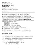
Removing the NAM from a 1-Slot Housing
1.
Disconnect the power cord/transformer, first from the power outlet, then from the
rear of the FrameSaver unit.
2.
Disconnect the other cables.
3.
Using a small flat-blade
screwdriver, gently pry open
the housing at each of the four
connecting tab points.
Be careful not to damage the
housing (using a screwdriver
that is too big could damage
the housing.)
4.
Remove the cover and lift
the NAM and its integrated
I/O card/backplane (rear
panel) from the base.
5.
Lay the NAM on an
electrostatic discharge-
protective work surface,
component side up, with
the card connectors on the
left-hand side.
!
98-15043a
98-15044a
Integrated
I/O Card/Backplane
NAM
Base

4
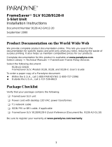
Removing the NAM from a Multislot Housing
The illustration shows the 14-slot access carrier as the housing.
1.
Unscrew the captive screws from
the ejector latches on front of the
carrier.
2.
Press open the ejector latches to
disengage the card.
3.
Supporting the card by its edges,
pull straight out until the card clears
the carrier.
4.
Lay the NAM on an electrostatic
discharge-protective work surface,
component side up, with the card
connectors on the left-hand side.
Proceed to
Removing a DBM
on page 5 if transferring a DBM to another NAM or
replacing a DBM. Otherwise, proceed to
Installing a DBM
on page 6.
98-16209
Ejector
Latches
Front View

5
Removing a DBM
1.
Remove the screws and washers from the three standoff posts that hold the DBM to
the NAM, and set them aside.
2.
Turn the NAM over and remove the screws and washers on the underside of the
NAM, and set the standoff posts, screws, and washers aside.
3.
Turn the NAM over again so the DBM is on top.
4.
Work the DBM away from the NAM by very carefully and gently pulling and rocking
the DBM connectors away from the NAM connectors. Work first from one side, then
the other until the DBM is free.
Be careful not to bend any pins.
98-15228a
Connectors
DBM
Pins
Standoff
Posts
Screws/Washers
Screws/Washers

6
Installing a DBM
Refer to the illustration in
Removing a DBM
on page 5 when following this procedure.
1.
Remove the DBM, standoff posts, screws and washers from the shipping box.
2.
Position a standoff post at one of the three holes in the NAM, put a screw through a
washer, insert the screw from the underside of the NAM, and tighten the screw to
hold the standoff post in place.
3.
Install the other standoff post(s) in the same way.
4.
Hold the DBM, pin side down, so the two sets of pins are aligned with their
respective connectors. Carefully match the pins to the holes of the two connectors.
5.
Press the pins and connectors together until both pin sets are firmly seated.
Be careful not to force or bend any pins.
6.
Insert the remaining screws and washers into the standoff post holes on the DBM,
and tighten.
Reinstalling the NAM
Select the appropriate procedure for reinstalling the NAM in its housing.
Reinstalling the NAM in a 1-Slot Housing
Refer to the illustrations in
Removing the NAM from a 1-Slot Housing
on page 3, if
necessary.
1.
Reinstall the NAM in its housing, snapping the cover and base together at each of
the four connecting tab points.
2.
Reconnect the cables.
Reinstalling the NAM in a Multislot Housing
Refer to the illustration in
Removing the NAM from a Multislot Housing
on page 4, if
necessary.
1.
Align the NAM with the upper and lower tracks of the slot.
2.
Slide forward until the NAM seats. Be careful not to force or bend any pins.
3.
Close both the upper and lower ejector latches on the carrier to lock in place, then
tighten the captive screws.
Installing the ISDN Cable
Select the appropriate procedure for the DBM being installed.

7
Installing a BRI Cable
1.
Insert the 8-pin connector on the ISDN-U cable into the DBM interface
(or BKP interface on a FrameSaver 9620).
2.
Insert the other end of the cable into the ISDN service RJ49C jack.
3.
Reconnect the power cord, first to the rear of the FrameSaver unit, then to the
power outlet.
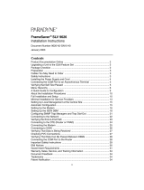
Installing a PRI Cable
1.
Insert the 8-pin connector on the
ISDN cable into the DBM interface.
2.
Insert the other end of the cable
into the ISDN service RJ48C jack.
98-16237
(FrameSaver 9126
Shown)
POWER
COM
DBM
DSX-1
MDM
NET
DSX
RJ49C
Jack
N
E
T
1
D
B
M
M
D
M
D
S
X
SINGLE
T1 NAM
RJ48C
Jack
NET 1
98-16206
RJ11C
Jack
DBM
MDM

8
Setting Up the DBM
Once the DBM is installed, it must be set up for dial backup. Another DBM must be
installed at the far end before backup can take place.
The DBM at one end of the link must be set up to place a call when there is a failure and
the other DBM must be configured to answer the call. The recommended method is for
remote sites to place the calls (usually with BRI DBMs) and for the central site to answer
calls (usually with a PRI DBM).
The following guidelines apply.
Central site configuration guidelines:
— Configure a Link Profile for each remote site.
— Configure the unit to answer calls from the remote sites.
— Leave Automatic Backup Configuration disabled.
— Manually create alternate DLCIs on the ISDN Backup Link.
— Manually specify ISDN DLCIs as alternate DLCIs for the PVC Connection after
the primary DLCIs have been automatically discovered from the primary
network Link LMI or manually configured.
Remote site configuration guidelines:
— Configure a Link Profile for the central site in the first link profile, called
HQ_Site. This ensures that a backup DLCI will be created automatically on the
backup link for each DLCI discovered on the network interface using the central
site’s link profile.
— Configure the unit to originate calls to the central site if a PRI DBM is installed.
A BRI DBM is already configured to originate calls.
— Enable the Automatic Backup Configuration feature if the unit has a PRI DBM.
A BRI DBM already has this feature enabled.
To set up the DBM for dial backup:
1.
Configure the DBM interface.
Main Menu
→
Configuration
→
ISDN
→
Physical
2.
Minimally, set the following configuration options:
— Interface Status is set to Enable.
— Originate or Answer is set to Answer for a central site, and set to Originate for a
remote site.
— Local Phone Number 1 is entered, plus the following:
FrameSaver Unit with BRI FrameSaver Unit with PRI
Configure the B-channels:
Service Profile ID1 (SPID)
Local Phone Number 1
Service Profile ID2 (SPID)
Local Phone Number 2
Configure T1 physical characteristics to
match the service provider’s settings.
Local Phone Number

9
3.
S
ave the configuration and return to the ISDN menu.
4.
Select Link Profiles, then type
n
(New) and press Enter.
5.
Set up the ISDN Link Profiles.
— Name for the destination entered (e.g., Tampa). The default setting is HQ_Site.
— Link Status is set to Auto.
— Phone numbers entered:
NOTE:
Remember to include local dial-out numbers (i.e., 9, then the number).
6.
If configuring a central site unit proceed to Step 11.
If configuring a remote site unit, proceed to Step 11.
7.
S
ave the configuration and return to the ISDN menu.
8.
Select DLCI Records, New, and press Enter. Minimally, configure the following
options to create DLCI records for the link:
— DLCI number
— DLCI Type is set to Multiplexed if a multiplexed DLCI is being backed up.
9.
S
ave the configuration and return to the Configuration Edit/Display menu.
10.
Select PVC Connections, then N
ew. Minimally, configure the following options to
create a PVC connection to be backed up.
— Alternate Destination Link name entered (e.g., Tampa). See the ISDN Link
Profile Name.
— Alternate Destination DLCI.
— Alternate Destination EDLCI if a multiplexed DLCI.
11.
S
ave the configuration and return to the Configuration Edit/Display menu.
12.
Select Auto Backup Criteria.
13.
Enable Auto Backup.
Originating FrameSaver Unit Answering FrameSaver Unit
Outbound Phone number. Valid
characters can include:
Numbers (0–9)
Special characters * and #
Spaces
Parentheses ( )
Inbound Calling ID1 and ID2. These are
the phone numbers of units that calls will
be accepted from.
Valid characters can include:
Numbers (0–9)

10
14.
Specify When Auto Backup Allowed – Always or Restrict. If Restrict is selected,
specify the days and hours of the week during which automatic backup can take
place.
15.
Save the change and return to the Configuration Edit/Display menu.
See
Setting Up An ISDN DBM for Dial Backup
in
Setup
of the User’s Guide for additional
information.
Verification Checklist
❑
Verify the ISDN lines by checking the DBM Interface Status.
Main Menu
→
Status
→
DBM Interface Status
— If Line Status displays Active, the ISDN line is operational.
— If Line Status displays an invalid (Inv) status (e.g., Inv SPID), verify that you
entered ISDN physical options correctly.
❑
Check backup setup.
— Disconnect the network cable at the remote site.
— Check the status of the FrameSaver unit:
Main Menu
→
Status
→
System and Test Status
→
Health and Status column
— Wait as the originating DBM places the backup call. The originating unit BKP
LED starts blinking.
When the answering FrameSaver unit receives the call, its BKP LED starts
blinking, and the
ISDN Active
message appears.
The BKP LEDs of both units stop blinking and remain on when the connection
is made, and the
Backup Active
message appears.
❑
Verify that data is passing between DBMs by selecting a backup link.
Main Menu
→
Status
→
Performance Statistics
→
Frame Relay
If data is being passed, Frames/Characters Sent and Received (Frame Relay Link)
and Status Msg Received (Frame Relay LMI) increment each time the screen is
R
efreshed.
A PVC Connectivity test can also be run if the ISDN DLCI is multiplexed.
Main Menu
→
Te s t
→
ISDN PVC Tests
→
[DLCI Number]
→
Connectivity
→
Start
See the User’s Guide or Technical Reference for additional information.

11
Setting Up Automatic Backup Configuration
Only applicable to a FrameSaver SLV 9191/9192/9195, the Automatic Backup
Configuration feature is used to automatically create alternate DLCI records and PVC
connections on the ISDN DBM (backup) interface when there is a failure of the primary
link or DLCI, or LMI is Inactive. This feature should be disabled for the central site unit,
but enabled for the remote unit.
Automatic backup can be changed at any time via the Auto Backup Criteria configuration
options. Specific days and times that backup will be allowed can also be specified. The
following table describes what happens when Auto Backup is enabled or disabled.
See
Changing the Automatic Backup Configuration
in
Setup
and
Configuring Auto
Backup Criteria
in
Configuration Options
of the User’s Guide for more information.
Auto Backup Description
Enable Auto-configuration of backup is enabled and traffic is
rerouted to the backup (alternate) interface when a failure
occurs.
The FrameSaver unit automatically enables the Alternate
Link configuration option and creates an Alternate DLCI
and EDLCI, and traffic is rerouted over the backup
interface.
Disable
(Default)
Auto-configuration of backup is disabled and traffic is not
rerouted to the backup interface.

12
Faceplate LEDs
The FrameSaver unit’s faceplate includes LEDs (light-emitting diodes) that provide
status on the FrameSaver unit and its interfaces. In addition, it provides backup status
for FrameSaver units equipped with an ISDN DBM.
See the BKP (backup) and ALM (alarm) LEDs when verifying DBM setup and operation.
For additional LED information, see the User’s Guide.
Label Indication Color What It Means
OK Power and
Operational
Status
Green ON – FrameSaver unit has power and is
operational.
OFF – FrameSaver unit is in a power-on
self-test, or there is a failure.
ALM Operational
Alarm (Fail)
Red ON – FrameSaver unit has just been reset,
or an error or fault has been detected.
OFF – No failures have been detected.
TST Test Mode Yellow ON – Loopback or test pattern in progress,
initiated locally, remotely, or from the
network.
OFF – No tests are active.
BKP* Backup Yellow ON – FrameSaver unit is in Backup mode;
that is, the backup link has been established,
and backup is in progress through the
specified Alternate Destination Link.
OFF – FrameSaver unit is not in Backup
mode.
Blinking ON and OFF (Rate: 1 Hz) –
Alternate Destination Link is being
established, but no data has been passed.
* When an ISDN BRI DBM is installed, if the OK LED comes on during power
recycling, then goes off, the ISDN BRI DBM may have failed.

13
Technical Specifications
Specification Criteria
ISDN BRI DBM
ISDN BRI DBM Interface
Physical interface
Service supported
Data rates
ISDN BRI U-interface: One 8-position modular keyed
USOC RJ49C jack
RJ49C
Capability Package B for 1B-channel service, or
Capability Package I for 2B-channel support, NI-1
(supporting up to two B-channels)
56 kbps and 64 kbps
Standards Compliance
ANSI T1.601 – 1992 (physical layer)
Bellcore SR-NWT-001937, Issue 1 – February 1991
ITU Q.921 – 1992 (link layer)
ITU Q.931 – 1993 (network layer)
TR-TSY-00860, ISDN Calling Number Identification
Services – February 1989, and
Supplement – June 1990
Power Consumption
60 mA at 15 VDC
Average power .9 watt
Weight
0.27 lbs. 4.3 oz. (0.12 kg 122 grams)
Switch Compatibility
National ISDN-1 (NI-1)
Switched Network Interface
One USOC RJ45 8-pole keyed modular plug and
jack, specified in ISO/IEC 8877
Transmit Interface
Signal Level
Impedance
13.5 dBm nominal over frequency band,
0 Hz – 80 kHz
135Ω
Receive Interface
Dynamic Range
Impedance
Operates on 2-wire loops, defined in
ANSI T1.601-1992
135Ω
Modulation and Frequency
2B1Q line coding with 4-level amplitude modulation
(PAM) at 80 kbps
Channel Equalization
Receiver Automatic adaptive equalizer with echo cancellation

14
ISDN PRI DBM
ISDN PRI DBM Interface
Physical interface
Service supported
Data rates
Framing format
Coding format
Line Build-Out (LBO)
ANSI PRM
8-position modular unkeyed USOC RJ48C jack
RJ48C
PRI, NI-2, ATT 4ESS, or ATT 5ESS custom
(supporting up to 23 B-channels), with
Circuit-Switched Data capability.
1.536 kbps
D4, ESF
B8ZS
0.0 dB, –7.5 dB, –15 dB, –22.5 dB
Selectable
Standards Compliance
ANSI T1.403 – 1989 (physical layer) and
AT&T 62411
Bellcore SR-NWT-002120, Issue 1 – May 1992
ITU Q.921 – 1992 (link layer)
ITU Q.931 – 1993 (network layer)
TR-TSY-00860, ISDN Calling Number Identification
Services – February 1989, and
Supplement – June 1990
Power Consumption
8 mA at 120 VAC
Average power 1 watt
Weight
0.15 lbs. 2.4 oz. (0.07 kg 68 grams)
Switch Compatibility
National ISDN-2 (NI-2),
ATT 4ESS, or
ATT 5ESS
Framing Format
D4, ESF
Coding Format
B8ZS
Line Build-Out (LBO)
0.0 dB, –7.5 dB, –15 dB, –22.5 dB
ANSI PRM
Selectable
Specification Criteria

15
Pin Assignments
Since FrameSaver SLV units use standard connectors, there is no need to order, buy, or
make special cables. You can use any standard straight-through cable for the DBM
interface.
ISDN BRI/U Interface Pin Assignments
ISDN PRI Interface Pin Assignments
Function Circuit Direction Pin Number
BRI Transmit/Receive Ring DBM4 To/From Local
Loop
4
BRI Transmit/Receive Tip DBM5 To/From Local
Loop
5
Function Circuit Direction Pin Number
PRI Receive Ring DBM1 From Local Loop 1
PRI Receive Tip DBM2 From Local Loop 2
PRI Transmit Ring DBM4 To Local Loop 4
PRI Transmit Tip DBM5 To Local Loop 5

16
Warranty, Sales, Service, and Training Information
Contact your local sales representative, service representative, or distributor directly for
any help needed. For additional information concerning warranty, sales, service, repair,
installation, documentation, training, distributor locations, or Paradyne worldwide office
locations, use one of the following methods:
Internet:
Visit the Paradyne World Wide Web site at
www.paradyne.com
.
(Be sure to register your warranty at
www.paradyne.com/warranty
.)
Telephone:
Call our automated system to receive current information by fax or to
speak with a company representative.
— Within the U.S.A., call 1-800-870-2221
— Outside the U.S.A., call 1-727-530-2340
Document Feedback
We welcome your comments and suggestions about this document. Please mail them to
Technical Publications, Paradyne Corporation, 8545 126th Ave. N., Largo, FL 33773, or
send e-mail to
userdoc@paradyne.com
. Include the number and title of this document
in your correspondence. Please include your name and phone number if you are willing
to provide additional clarification.
Trademarks
FrameSaver is a registered trademark of Paradyne Corporation. All other products and
services mentioned herein are the trademarks, service marks, registered trademarks, or
registered service marks of their respective owners.
"
*9000-A2-GN19-80*
Copyright
©
2001 Paradyne Corporation. Printed in U.S.A.
/