Page is loading ...

Read through the installation instructions
carefully before installing your Waterous
Drain Valve.
Table of Contents
Description 1. . . . . . . . . . . . . . . . . . . . . . . . . . . . . . . . . . . . .
Panel Mounted Drain Valve
Installation 2. . . . . . . . . . . . . . . . . . . . . . . . . . . . . . . . . . . .
Components 2. . . . . . . . . . . . . . . . . . . . . . . . . . . . . . . . . .
Dimensions 3. . . . . . . . . . . . . . . . . . . . . . . . . . . . . . . . . . .
Drain Ports 3. . . . . . . . . . . . . . . . . . . . . . . . . . . . . . . . . . .
Cable Operated, Remote Mounted Valve
Installation 4. . . . . . . . . . . . . . . . . . . . . . . . . . . . . . . . . . . .
Components 5. . . . . . . . . . . . . . . . . . . . . . . . . . . . . . . . . .
Dimensions 6. . . . . . . . . . . . . . . . . . . . . . . . . . . . . . . . . . .
Drain Ports 7. . . . . . . . . . . . . . . . . . . . . . . . . . . . . . . . . . .
Fire Pump Drain Locations
CM Series Pumps 8. . . . . . . . . . . . . . . . . . . . . . . . . . . . .
CS Series Pumps 8. . . . . . . . . . . . . . . . . . . . . . . . . . . . .
All content in this instruction is property of the Waterous Company. Instructions subject to change withou
t
Waterous Company 125 Hardman Avenue South, South St. Paul, Minnesota 55075 USA (651) 450-5000
Instructions subject to change without notice.
Visit us at www.waterousco.com
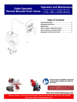
Cable Operated Remote Mounted Valve
Panel Mounted Valve
Section
3008
Form No.
F-1031
Issue Date
03/31/95
Rev. Date
08/16/10
Drain Valves Installation Instructions

F-1031, Section 3008 Page 2 of 8
Description
The Waterous drain valve provides a convenient means of
draining a fire pump and related equipment after each
operation. Its design permits simultaneous draining of at
least eight lines. It consists essentially of a stainless steel
sliding plunger in a bronze body.
Two valves are offered. The panel mounted valve is hori
zontally mounted on the pump operator's panel.
The remote mounted valve is vertically mounted on the
pump transmission, or at a remote location, and is oper
ated by a flexible cable from the pump control panel. This
valve is designed so that discharge pressure will act on
the plunger to keep the valve closed when the valve has
been manually closed. The correct installation procedure
and the correct drain connections must be made for the
valve to function properly.
Panel Mounted Valve
Installation
1. Select a valve mounting location on the fire pump
control panel or other convenient locations which will
be lower than all the points to be drained. Make sure
the mounting location is rigid.
2. Drill holes in panel to mount valve and bezel plate
(see Page 3 for panel hole layout).
3. Using (2) socket head screws, 1/4-20 x 5/8, attach
drain valve to the panel. Make sure the valve inlet
ports are pointing up.
4. Using (4) socket head screws, 6-32 x 3/4 and 6-32
hex nuts, attach bezel plate to the panel.
5. Install hex nut, 3/8-16 and control knob.
6. Use 3/8 inch tubing and fittings to connect the pump
and accessory drain openings to drain valve. (The
drain valve ports are 1/4 inch NPT.) Make sure all
drain lines slope downward to the drain valve, and are
free of low points.
Drain lines may be connected to (8) 1/4 NPT ports in
any manner. There are no specific intake, discharge
or isolated ports. See Page 3.
Note: Do not connect the following drains to this
drain valve. A separate drain valve must be used
for each:
·Discharge relief valve cap
·Discharge pilot valve (on apparatus panel)
·Extra pressure stage (model CMH or CSH pumps)
·Intake relief valve cap
·Foam manifold
·Passageways which carry foam
7. Install pipe plugs in unused ports of drain valve.
Panel Mounted Valve - Components

F-1031, Section 3008 Page 3 of 8
Panel Mounted Valve - Dimensions
Panel Mounted Valve - Drain Ports
PL82087_2
Drain lines may be connected to (8)
1/4 NPT ports in any manner. There
are no specific intake, discharge or
isolated ports.
·Intake relief valve cap
·Discharge relief valve cap
·Discharge pilot valve (on apparatus panel)
·Extra pressure stage (model CMH or CSH pumps)
·Foam manifold
·Passageways which carry foam
Note: Do not connect the following drains to the drain valve.
A separate drain valve must be used for each:

F-1031, Section 3008 Page 4 of 8
Installation
1. On a midship mounted pump with a C10, TC10, C20,
TC20 or W series pump transmission, the drain valve
can be mounted to the mounting pad on the front of
the transmission. If the pump has a different type of
transmission, select a valve mounting location which
will be lower than all the points to be drained. Make
sure the mounting location is rigid. At the mounting
location, drill two 13/32 inch holes, one above the oth
er, 1-1/2 inch apart.
2. Attach the drain valve mounting bracket with 3/8 inch
bolts, washers and nuts.
3. Select a mounting location for the bezel plate which
will permit the control cable to curve gradually down to
the drain valve without sharp bends. Drill holes to
install bezel plate to panel (see Figure 5). Position the
bezel plate, align screw holes and install screws,
washers and nuts.
4. Insert the control cable through the center hole in the
bezel plate and install lock nuts provided with the con
trol cable to hold it in place.
5. Route the control cable down through the drain valve
mounting bracket, and install but do not tighten lock
nuts. Insert the cable eyelet in slot of valve stem and
attach with cotter pin.
6. Adjust the end of control cable vertically in the mount
ing bracket to permit full travel of the valve stem, and
tighten control cable lock nuts. The control cable
should be adjusted so that in the fully closed position,
the control handle will be approximately 1/16th of an
inch away from the cable housing at the panel.
NOTE: Make sure that plunger bottoms in body
with the valve closed. If the valve is not adjusted
to seat the plunger completely, the valve will not
function properly.
7. Use 3/8 inch tubing and fittings to connect the pump
and accessory drain openings to drain valve. (The
drain valve ports are 1/4 inch NPT.)
For models CM and CS series pumps, be sure to
connect all drain lines as shown on the drain location
diagrams shown on page 8. For other pump models
be sure to connect all drain lines as shown on page 7.
If drain lines are not connected properly, the drain
valve and other accessories may not function prop
erly. Also, make sure all drain lines slope downward to
the drain valve, and are free of low points.
NOTE: Do not connect the following drains to the
drain valve. A separate drain should be used for
each:
·Discharge Relief Valve Cap
·Discharge Pilot Valve (on apparatus panel)
·Extra Pressure Stage (CMH and CSH pumps)
·Intake Relief Valve Cap
·Foam Manifold
·Passageways which carry foam
8. Install pipe plugs in unused ports of drain valve.

F-1031, Section 3008 Page 5 of 8
Cable Operated Valve - Components
Cable
Bezel Panel
Handle
Mounting Bracket
Drain Valve
3/8 in. Bracket Mounting Hardware
Torque to 36-40 LB-FT.
8 x 1/4 NPT
Remove Hex Nuts
and Washers
Hex Nut and Lock
Washer from Cable,
3/8 in.
Plain Washers
3/8 in.
Hex Nut and Lock
Washer from Cable,
3/8 in.
Cotter Pin
3/16 in.
Cable Connection to Valve
Handle
Bezel Panel Plate
Panel or Other Support
Cable
Leave this 1/2 in.
Nut and Washer on
the Cable
Remove 1/2 in. and
1/4 in. Nuts from
End of Cable
(4) No. 6-32 x 3/4 in.
Screws and Hex
Nuts
1/2 in. and 1/4 in.
Hex Nuts from
Control Cable
Cable Connection to Panel

F-1031, Section 3008 Page 6 of 8
Cable Operated Valve - Dimensions
Bezel Plate
Panel
Bezel Plate Mounting,
Hardware Supplied by Waterous
Discharge Port
Intake Port
Isolated
Port
8 x 1/4 NPT
Discharge Port
Discharge
Port
Intake Port
Isolated
Ports
Mounting Flange,
May be mounted on C20,
WB Series Transmissions,
TC20 Series PTO's or an
OEM supplied bracket.
Torque 3/8 in. screws to
36-40 LB-FT.

F-1031, Section 3008 Page 7 of 8
Drain Valve Ports
Discharge Port Discharge Port
Intake Port
Intake Port
Isolated Port
Isolated Port
Explanation of Drain Valve Ports
Discharge Ports (3)
All pump and accessory passages which are normally
under full discharge pressure.
Intake Ports (2)
All pump and accessory passages which are connected to
pump intake.
Isolated Ports (3)
Pump passages such as first stage discharge and second
stage intake are connected here. These ports are not
connected to pump intake and are not under full discharge
pressure.
Note: The following drain valves are not to be con
nected to the drain valve. Separate drains must be
used for these.
·Intake relief valve cap
·Discharge relief valve cap
·Discharge pilot valve (on apparatus panel)
·Extra pressure stage (model CMH or CSH pumps)
·Foam manifold
·Passageways which carry foam

F-1031, Section 3008 Page 8 of 8
Drain Locations, CM Series Pumps
Drain Locations, CS Series Pumps
Manifold Drain Valve Details
Forward
Bottom View
Discharge Pilot Valve
(On apparatus panel)
Drain Separately
(Optional both ends)
Manifold Drain Valve
Discharge Relief Valve Cap
Drain Separately
Discharge
Relief
Valve
1
2
3
4
5
6
7
8
Intake Volutes
Discharge Volute
Crossover Passage
Main Discharge Barrel
Relief Valve Elbow or Adapter
Mechanical Seal/Packing Chambers
Relief Valve Body
Intake Fittings (Depends on type of Intake fitting)
Manifold Drain Valve Details
NOTE: If the pump has a foam manifold,
its drains should be plumbed into a
separate drain valve. Do not plumb into
drain valve used for the pump.
23
647
581
7
5
6
4
1
1
2
8
8
3
7
Discharge Relief Valve Cap
Drain Separately
Manifold Drain Valve
(Optional both ends)
Forward
Bottom View
1st Stage Volute
2nd Stage Volute
2nd Stage Intake
Transfer Valve
Main Discharge Barrel
Relief Valve Elbow or Adapter
Relief Valve Body
Intake Fittings (Depends on type of Intake fitting)
Discharge Pilot Valve
(On apparatus panel)
Drain Separately
Discharge Relief Valve
Seal Cooling Line
NOTE: If the pump has a foam manifold,
its drains should be plumbed into a sep‐
arate drain valve. Do not plumb into drain
valve used for the pump.
/