Page is loading ...

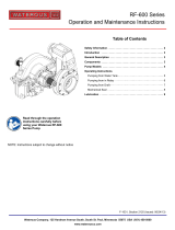
S100 Series Centrifugal
Fire Pumps
Operation and Maintenance
Form No.
F-1031
Section
2117
Issue Date
02/22/02
Rev. Date
3/24/23
Table of Contents
Safety Information----------------------------------------------- 2, 3
Introduction . . . . . . . . . . . . . . . . . . . . . . . . . . . . . . . . . . . . . 4
General Description . . . . . . . . . . . . . . . . . . . . . . . . . . . . . . 4
Components .................................................................... 4
Options . . . . . . . . . . . . . . . . . . . . . . . . . . . . . . . . . . . . . . . . . 4
Pump Models . . . . . . . . . . . . . . . . . . . . . . . . . . . . . . . . . 5, 6
Operating Instructions:
Transmission . . . . . . . . . . . . . . . . . . . . . . . . . . . . . . . . . . 7
Pumping from Water Tank ................................................ 7
Pumping from Hydrant or in Relay .............................. 8
Pumping from Draft ..................................................... 9
Fire Hose Testing ...................................................... 10
Maintenance:
Corrosion Protection:
Optional Intake Screens ................................... 11
Optional Anodes ............................................... 11
Mechanical Seal . . . . . . . . . . . . . . . . . . . . . . . . . . . . .. . 12
Overheat Protection Manager (OPM) . . . . . . . . . . . . 12
Lubrication . . . . . . . . . . . . . . . . . . . . . . . . . . . . . . . . . . . 13
Read through the safety information and
operating instructions carefully before
using your Waterous Fire Pump.
Visit us at www.waterousco.com
Waterous Company 125 Hardman Avenue South, South St. Paul, Minnesota 55075 USA (651) 450-5000
Instructions subject to change without notice.

F-1031, Section 2117
Page 2 of 13
Safety Information
Read through the safety information and operating instructions carefully before using
your Waterous Fire Pump.
! WARNING
Scalding Water Hazard. May result in serious burns.
When operating the pump, be sure to open at least one
discharge valve slightly to prevent the pump from over-
heating. If the pump runs for a few minutes completely
closed, it may heat the water enough to scald someone
when the valve is opened. Overheating can damage the
packing, seals and other pump parts. If the apparatus
builder has installed a by-pass system or other provision
designed to prevent overheating, opening a discharge
valve may be unnecessary.
! WARNING
Limit intake pressure to 75 psi (5.2 bar) if possible. Al-
though the pump will operate properly with higher intake
pressure, such operation will greatly accelerate me-
chanical seal wear.
! WARNING
Pressure Hazard. May result in personal injury.
Prior to connection or removal of hoses, caps or other
closures with pump intake or pump discharge connec-
tions, relieve pressure by opening drains or bleeder
valves. Bleeder valves should also be used while filling
a hose connected to an intake with water.
! WARNING
Unexpected Truck Movement. May result in serious
personal injury or death.
Failure to properly shift transmission in accordance to
the transmission operating instructions may result in
unexpected truck movement which may result in serious
personal injury or death.
! WARNING
Death or serious personal injury might occur if proper
operating procedures are not followed. The pump oper-
ator, as well as individuals connecting supply or dis-
charge hoses to the apparatus must be familiar with
these pump operating instructions as well as other op-
erating instructions and manuals for the apparatus, wa-
ter hydraulics and component limitation.

F-1031, Section 2117
Page 3 of 13
Safety Information
Read through the safety information and operating instructions carefully before using
your Waterous Fire Pump.
WARNING
Hose Testing Hazard. May result in serious personal injury.
Due to a potential for catastrophic hose failure during service testing of fire hose, it is vital that safety precautions be taken to
prevent exposure of anyone to this danger. Fire pumps on fire department apparatus are not designed for and should not be
used for service testing of fire hoses. Hose testing machines should be used for service testing of fire hoses.
WARNING
Pressure Hazard. May result in serious personal injury.
If a fire pump on a fire department apparatus is used for service testing of fire hoses, the procedures in NFPA 1962 MUST
be followed including the use of a fire department gate valve with a ¼-inch (6 mm) hole drilled through the gate installed
between the fire apparatus discharge outlet and the hose test layout to prevent a volume surge from the pump in the event a
hose bursts during testing.
WARNING
Scalding Water Hazard. May result in serious burns.
If a fire pump on a fire department apparatus is used for service testing of fire hoses, pump discharge water must be
circulated through a by-pass system or discharged through a slightly open discharge valve, or some other provision must be
used to prevent overheating. If the pump runs for a few minutes without adequate flow through the pump, water may be
heated enough to scald someone when a valve is opened.

F-1031, Section 2117
Page 4 of 13
Introduction
This instruction contains the information needed for operation and maintenance of S100 Series centrifugal pumps.
General Description
The S100 series pumps are single stage centrifug
®
al end suction pumps providing capacities up to 2000 GPM (7570
L/min).S100 models are midship mounted with a Victaulic intake fitting, S101 models are midship mounted with an intake
crosspipe.
Body Assembly
Components
Mechanical Seal
This assembly includes a double stripping edge volute body
to minimize radial forces at all flow rates, intake adapter and
related parts. The body and adapters are ductile iron.
Impeller Shaft Assembly
This assembly consists of a bronze, flame-plated impeller
mounted on a stainless steel shaft, wear rings, mechanical
seal and related parts. The impeller is balanced and the im-
peller shaft is supported by ball bearings.
The mechanical seal consists of a flat, highly polished
(lapped), spring-fed carbon ring that is sealed to and rotates
with the impeller shaft. It presses against a highly polished
(lapped) silicon carbide mating ring that is sealed in the vo-
lute body. This seals the shaft and prevents air from entering
and water from leaving. A mechanical seal does not leak or
drip water, even when pumping.
Intake Screens Options
Anodes
Zinc die cast screens are normally used in the intake fit‐
tings, with brass screens available optionally. Although the
screens are chemically treated (coated) to inhibit corro‐
sion, the water being pumped may still corrode the
screens. Such corrosion is ``sacrificial''; that is, it will help
prevent corrosion in the rest of the pump the same way
the magnesium anodes protect the metal parts of a water
heater.
As additional corrosion protection for iron body pumps,
Waterous has anodes available to fit any unused opening
in the intake fitting. Anodes provide an additional
sacrificial surface to the water to supplement the intake
screens.
Overheat Protection Manager (OPM)
The Overheat Protection Manager (OPM) acts as a safety
device by releasing hot water to the ground or back to the
water tank from the discharge area of the pump.
OPERATION LIMITS: Do not operate pump beyond max. pressure (300 psi) or max. speed (4500 rpm).
Fail to do that may result in personal injury or premature pump failure.

F-1031, Section 2117
Page 5 of 13
S100C20 Series
Pump Models
S100C22 Series
End Suction Intake
C20 Series Chain Drive Transmission End Suction Intake
C22 Series Chain Drive Transmission
S101C20 Series S101C22 Series
Crosspipe Intake
C20 Series Chain Drive Transmission Crosspipe Intake
C22 Series Chain Drive Transmission

F-1031, Section 2117
Page 6 of 13
Pump Models (Cont’d)
S100PA Series
S100D Series
End Suction Intake
PA Series Chain Drive Transmission End Suction Intake Direct
Drive, Pedestal Mounted
S101C20 Series S100D Series

F-1031, Section 2117
Page 7 of 13
! WARNING
Pressure Hazard. May result in personal injury or
death.
Prior to connection of hoses, caps or other closures
with pump intake or pump discharge connections, re-
lieve pressure by opening drains.
! WARNING
Scalding Water Hazard. May result in serious
burns.
When operating the pump, be sure to open at least
one discharge valve slightly to prevent the pump from
overheating. If the pump runs for a few minutes com-
pletely closed, it may heat the water enough to scald
someone when the valve is opened. Overheating can
damage the packing, seals and other pump parts. If
the apparatus builder has installed a by-pass system
or other provision designed to prevent overheating,
opening a discharge valve may be unnecessary.
Operating Instructions
Transmission Operation
Refer to the C20 Transmissions: Operation and Maintenance Instructions, See F-1031-2413
Refer to the C22 Transmissions: Operation and Maintenance Instructions, See F-1031-2559
Refer to the PA Transmissions: Operation and Maintenance Instructions, See F-1031-2207
Pumping from Water Tank
6. Set relief valves or other pressure governing device to
desired pressure.
After Pumping
1. Open valve(s) in piping between water tank and pump
intake and at least one discharge valve.
2. Allow about 30 seconds for water to flow into pump.
NOTE: Priming the pump may be necessary due to air
trapped in piping.
3. S100D Only: Engage pump drive and accelerate en-
gine to obtain desired discharge pressure and capacity.
1. Disengage pump drive. If equipped with a C20 transmis-
sion (S100C20 or S101C20) or C22 transmission
(S100C22 or S101C22) disengage pump drive in
accordance with the transmission instructions.
2. If pumping anything but clean water, remove all intake
and discharge caps, open all valves and open all drains.
Flush entire system with clean, fresh water for several
minutes to remove all traces of impurities.
3. If pump is kept full of water when not in use, make sure
water is clean and non-corrosive. Make sure the pump
is completely full or completely drained - never partially
full.
4. S100C20, S101C20, S100C22 and S101C22 Only:
Engage pump in accordance with transmission
instructions.
5. S100C20, S101C20, S100C22 and S101C22 Only:
Open discharge valves and accelerate engine to obtain
desired discharge pressure and capacity.
CAUTION
Freezing water hazard. May cause damage to
the pump.
If the pump is exposed to freezing temperatures,
drain all water from pump, lines and accessories.
4. Close all drains and install intake and discharge caps.
5. If truck is equipped with a priming pump, operate it until
fluid is discharged from priming pump discharge pipe.
If equipped with a priming tank, check fluid level and refill
if necessary.
! WARNING
Unexpected Truck Movement. May result in per-
sonal injury or death.
Failure to properly shift transmission in accordance
with the transmission operating instructions may result
in unexpected truck movement which may result in
serious personal injury or death.
! WARNING
Pressure Hazard. May result in personal injury or
death.
Prior to removal of hoses, caps or other closures with
pump intake or pump discharge connections, relieve
pressure by opening drains.
CAUTION
Do not attempt to pump more water than is avail-
able from the water tank. Always make sure the
intake pressure compound gage reading stays
above zero.
NOTICE
NOTICE

F-1031, Section 2117
Page 8 of 13
! WARNING
Pressure Hazard. May result in personal injury or
death.
Prior to connection of hoses, caps or other closures
with pump intake or pump discharge connections, re-
lieve pressure by opening drains or bleeder valves.
! WARNING
Scalding Water Hazard. May result in serious burns.
When operating the pump, be sure to open at least one
discharge valve slightly to prevent the pump from over-
heating. If the pump runs even for a few minutes com-
pletely closed it may heat the water enough to scald
someone when the valve is opened. Overheating can
damage the packing, seals and other pump parts.If the
apparatus builder has installed a by-pass system or oth-
er provision designed to prevent overheating, opening
a discharge valve may be unnecessary.
! WARNING
Unexpected Truck Movement. May result in person-
al injury or death.
Failure to properly shift transmission in accordance with
the transmission operating instructions may result in
unexpected truck movement which may result in serious
personal injury or death.
! WARNING
Pressure Hazard. May result in personal injury or
death.
Prior to removal of hoses, caps or other closures with
pump intake or pump discharge connections, relieve
pressure by opening drains or bleeder valves.
CAUTION
Limit intake pressure to 75 psi (5.2 bar) if possible.
Although the pump will operate properly with higher
intake pressure, such operation will greatly acceler-
ate mechanical seal wear.
Pumping from Hydrant or in Relay
4. S100C20, S101C20, S100C22 and S101C22 Only:
Open discharge valves and accelerate engine to obtain
desired discharge pressure and capacity.
5. Set relief valves or other pressure governing device to
desired pressure.
NOTE: Some fire departments operate at a minimum
intake pressure of 10 psi (.7 bar) when pumping
from hydrant or in relay to prevent a •soft" intake
hose from collapsing.
After Pumping
1. S100D Only: Engage pump drive and accelerate en-
gine to obtain desired discharge pressure and capacity.
2. S100C20, S101C20, S100C22 and S101C22 Only:
Engage pump in accordance with transmission
instructions.
3. Open intake, hydrant and other valves as necessary to
allow water to enter the pump.
NOTE: Bleeder valves should be used while filling a
hose connected to an intake with water.
1.
Disengage pump drive. If equipped with a C20 transmis-
sion (S100C20 and S101C20) or C22 transmission
(S100C22 or S101C22) disengage pump drive in
accordance with the transmission instructions.
2. If pumping anything but clean water, remove all intake
and discharge caps, open all valves and open all drains.
Flush entire system with clean, fresh water for several
minutes to remove all traces of impurities.
3. If pump is kept full of water when not in use, make sure
water is clean and non-corrosive. Make sure the pump
is completely full or completely drained (never partially
full).
4. Close all drains and install intake and discharge caps.
5. If truck is equipped with a priming pump, operate it until
fluid is discharged from priming pump discharge pipe. If
equipped with a priming tank, check fluid level and refill
if necessary.
CAUTION
CAUTION
Do not attempt to pump more water than is available
from the hydrant or relaying pumper. Always make
sure the intake pressure compound gage reading
stays above zero.
NOTICE
NOTICE
NOTICE

F-1031, Section 2117
Page 9 of 13
! WARNING
Pressure Hazard. May result in personal injury or
death.
Prior to connection of hoses, caps or other closures with
pump intake or pump discharge connections, relieve
pressure by opening drains.
! WARNING
Scalding Water Hazard. May result in serious burns.
When operating the pump, be sure to open at least one
discharge valve slightly to prevent the pump from over-
heating. If the pump runs even for a few minutes com-
pletely closed it may heat the water enough to scald
someone when the valve is opened. Overheating can
damage the packing, seals and other pump parts. If the
apparatus builder has installed a by-pass system or oth-
er provision designed to prevent overheating, opening a
discharge valve may be unnecessary.
! WARNING
Unexpected Truck Movement. May result in person-
al injury or death.
Failure to properly shift transmission in accordance with
the transmission operating instructions may result in
unexpected truck movement which may result in serious
personal injury or death.
Pumping from Draft
1. Prime the pump (see separate instructions supplied with
primer).
2. S100D Only: Engage pump drive and accelerate en-
gine to obtain desired discharge pressure and capacity.
3. S100C20, S101C20, S100C22 and S101C22 Only:
Engage pump in accordance with transmission
instructions.
4. S100C20, S101C20, S100C22 and S101C22 Only:
Open discharge valves and accelerate engine to obtain
desired discharge pressure and capacity.
5. Set relief valves or other pressure governing device to
desired pressure.
After Pumping
NOTE: To get full capacity, quick prime and maintain
pump efficiency:
a) Position vehicle as near as possible to water supply.
b) Avoid humps and sharp bends in intake hose. Make
sure no part of hose is higher than pump inlet. (Air pock-
ets in intake hose may cause loss of prime or erratic
pump action, and may reduce pump capacity.)
c) Make sure all intake connections are tight and discharge
valves are closed.
d) Immerse intake strainer at least two feet below water
surface to prevent pump from drawing air. (Whirlpools
forming above intake strainer indicate that strainer is too
close to surface of water.)
e) Make sure intake strainer is far enough from bottom to
prevent sand, gravel and other foreign matter from be-
ing drawn into the pump.
1. Disengage pump drive. If equipped with a C20 transmis-
sion (S100C20 and S101C20) or C22 transmission
(S100C22 or S101C22) disengage pump drive in
accordance with the transmission instructions.
2. If pumping anything but clean water, remove all intake
and discharge caps, open all valves and open all drains.
Flush entire system with clean, fresh water for several
minutes to remove all traces of impurities.
3. If pump is kept full of water when not in use, make sure
water is clean and non-corrosive. Make sure the pump
is completely full or completely drained (never partially
full).
4. Close all drains and install intake and discharge caps.
5. If truck is equipped with a priming pump, operate it until
fluid is discharged from priming pump discharge pipe.
If equipped with a priming tank, check fluid level and refill
if necessary.
CAUTION
Freezing water hazard.
May cause damage to the pump.
If the pump is exposed to freezing temperatures,
drain all water from pump, lines and accessories.
! WARNING
Pressure Hazard. May result in personal injury or
death.
Prior to removal of hoses, caps or other closures with
pump intake or pump discharge connections, relieve
pressure by opening drains.
NOTICE

F-1031, Section 2117
Page 10 of 13
Fire Hose Testing
WARNING
Hose Testing Hazard. May result in serious personal injury.
Due to a potential for catastrophic hose failure during service testing of fire hose, it is vital that safety precautions be taken to
prevent exposure of anyone to this danger. Fire pumps on fire department apparatus are not designed for and should not be
used for service testing of fire hoses. Hose testing machines should be used for service testing of fire hoses.
NFPA 1962 Standard for the Inspection, Care, and use of Fire Hose, Couplings, and Nozzles and the Service Testing of Fire
Hose provides requirements and testing procedures for service-testing fire hose at least annually. NFPA 1962 includes
procedures for service testing with either a hose testing machine or with a pump on a fire department fire apparatus.
WARNING
Pressure Hazard. May result in serious personal injury.
If a fire pump on a fire department apparatus is used for service testing of fire hoses, the procedures in NFPA 1962 MUST
be followed including the use of a fire department gate valve with a ¼-inch (6 mm) hole drilled through the gate installed
between the fire apparatus discharge outlet and the hose test layout to prevent a volume surge from the pump in the event a
hose bursts during testing.
During fire hose testing with a fire pump on a fire department fire apparatus, the fire pump is required to be operated at high
discharge pressure with little or no flow out of the apparatus.
WARNING
Scalding Water Hazard. May result in serious burns.
If a fire pump on a fire department apparatus is used for service testing of fire hoses, pump discharge water must be
circulated through a by-pass system or discharged through a slightly open discharge valve, or some other provision must be
used to prevent overheating. If the pump runs for a few minutes without adequate flow through the pump, water may be
heated enough to scald someone when a valve is opened.
CAUTION
If a fire pump on a fire department apparatus is used for service testing of fire hoses, operating the pump at high discharge
pressure with little or no flow may result in severe damage to the pump.
NOTICE

F-1031, Section 2117
Page 11 of 13
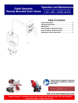
Threaded Anodes
Intake Screen
Threaded Anodes
Optional Intake Screens
Maintenance
Corrosion Protection
Once per month check to make sure the intake screens
are not clogged or damaged. Also check for corrosion,
and replace screens if damage is severe. For the screen
to adequately control corrosion, there must be a strong
electrical contact between the screen and the fitting.
Remove any corrosion, debris or paint from the counter
bore that will insulate the screen from the intake fitting. If
the screen does not fit tightly, adjust the gap of the slot
on the outside diameter of the screen to ensure a tight fit.
NOTE: These screens are die-cast which results in a
slight taper from one side to the other. Install the
screen with the thinner cross-section facing out to
minimize flow restriction.
Optional Anodes
Twice per year, remove the anodes and check for erosion
of the replaceable elements. Replace the elements if
more than half of either of the elements has eroded.
Anodes are normally mounted on the pump intake piping,
but they may also be installed in the discharge piping if no
intake mounting locations were available. Physical
mounting of the anode may be via an NPT tap or bolt-on
flange as described below.
NOTE: The replaceable elements must make contact
with water to be effective. Do not paint or use any
other coating on the replaceable elements.
Bolt-on Anodes
Unscrew the (4) hex head screws from the pump. If
elements require replacement, unscrew the hex head cap
screw.
NOTE: There is no need to remove the threaded
anode adapter from the anode flange for element
replacement. The screw was installed using thread
sealant so higher force than normal may be neces-
sary to remove.
Replace one or both elements as necessary. Install the
hex head screw using Loctite 242 (blue) on the screw
threads. Mount the anode assembly back on the fitting.
Threaded Anodes
NOTE: The 2-1/2 in. hex is threaded into a bushing
that should remain on the pump. Be sure to restrain
the bushing when removing the 2-1/2 in. hex.
Unscrew the 2-1/2 in. hex from the pump. If the elements
require replacement, unscrew the hex head cap screw.
NOTE: The screw was installed using thread sealant
so higher force than normal may be necessary to
remove.
Replace one or both elements as necessary. Install the
hex head screw using Loctite 242 (blue) on the screw
threads. Remove any paint or corrosion from the face
around the NPT tap on the pump. Apply thread sealant to
the threads and screw the 2-1/2 in. hex into the pipe tap
until tight.

F-1031, Section 2117
Page 12 of 13
CAUTION
Prolonged dry pump operation or operating a dry
pump at high speeds will reduce the life of the me-
chanical seal.
Mechanical Seal
A mechanical shaft seal is used and no adjustment is
required. When the pump operates, the water being
pumped cools and lubricates the shaft seal to prevent it
from overheating.
If the mechanical seal leaks, replace the entire seal.
The S100 is equipped with drain notches on the pump
body/transmission mounting flange or bearing housing. If
any water seeps through the mechanical seal in the fire
pump or oil seeps through the oil seal in the transmission
or bearing housing, a V-ring on the impeller shaft directs
the oil or water into the drain notches. This prevents water
from entering into the oil in the transmission/bearing
housing or oil from entering into the water supply of the
pump.
Overheat Protection Manager
Check the electrical circuit by pressing the test button
located on the panel plate every 100 hours of pump op-
eration or every six months, whichever comes first.
If the light does not flash, the light bulb or flasher may
need replacement (provided all wire connections are
solid).
NOTICE

F-1031, Section 2117
Page 13 of 13
Lubrication
1. Check the lubrication fluid level monthly by check-
ing the sight plug or by removing the oil level plug.
The fluid should be level with the bottom of the oil
level hole.
2. Change lubrication fluid and clean breather once a
year or after each 100 hours of operation, whichever
comes first. Lubrication fluid may be added through
the oil level hole or by removing the breather and
adding fluid through the opening. Any type of auto-
matic transmission fluid (ATF) may be used.
3. Quantities of lubrication fluid if system is completely
drained and refilled:
S100C20, S100C22, S100PA, S101C20 and S101C22
Series Models:
C20 and C22 Transmissions: Approximately 6 quarts
of ATF. PA Transmissions: Approximately 3 quarts of
ATF.
S100D Direct Drive Models:
Fill bearing housing with approximately 1/2 quart of
non-detergent SAE 30 oil.
C20 Transmission
C22 Transmission
PA Transmission S100D Bearing Housing
CAUTION
Low or excessive lubrication fluid may cause
damage.
If lubricant fluid level is low, locate source of leak
and repair. If level is high, loosen oil level plug
and drain until proper level is reached. If any
water drains out, change lubrication fluid and
determine source of water leakage and repair.
NOTICE
/