Page is loading ...

Waterous Fire Pumps may be ordered with a variety of accessories.
Refer to the following separate installation instructions as necessary:
Auto Tank Fill System
Butterfly Valves
CAF System
Discharge Valves
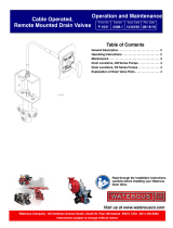
Drain Valves
Foam System:
Foam Pump
Foam Pump Flush Kit
Foam Fill
Dual Foam Injection Kit
Dual Tank Selector
Overboard Foam Pick-up
Remote Start Kit
Overheat Protection Manager (OPM)
Pump Shift (Pneumatic)
Pressure Control System:
Discharge Relief Valve
Intake Relief Valve
Pressure Governor
Priming System
Read through safety information
and installation instructions
carefully before installing your
Waterous Fire Pump.
Waterous Company 125 Hardman Avenue South, South St. Paul, Minnesota 55075 (651) 450-5000
www.waterousco.com
F-1031, Section 3014
Revised: 3/24/23
Fire Pump Models CXN, CXS and CXV
Installation Instructions
Note that Instructions are subject to change
without notice.
Model CXN
Model CXS
Model CXV

F-1031, Section 3014
Page 2 of 18
Table of Contents:
Safety Information…………………………………………………………… 3
Pump Orientation Definitions……………………………………………… 4
Pump Intake and Discharge Connections………………………………. 4
Available Pump Drives ……………………………………………………… 4
Pump Mounting………………………………………………………………. 5
Mounting Locations:
Pump Intake Adapter:
CXN, CXS and CXV Models…………………………………………… 5
Pump Transmissions:
With C20 or C22 Series Transmission:
Pump Mounted on Front (Input Shaft Side) of Transmission……. 6
Pump Mounted on Rear (Output Shaft Side) of Transmission….. 7
With Direct Drive, No Transmission…………………………………… 8
With PA Model Transmission………………………………………….. 9
With K Model Transmission…………………………………………… 10
With T Model Transmission…………………………………………… 11
With QB Model Transmission:
Pump Mounted on Front (Input Shaft Side) of Transmission……. 12
Pump Mounted on Rear (Opposite Side of Input Shaft) of
Transmission…………………………………………………………. 13
Optional Suspension Pin Mounting Method:
Models CXSK, CXSK and CXVK Only………………………………. 14
Transmission Oil Cooler Drain, K and T Models………….…………….. 15
Tachometer Connection:
Available on C20 Series and PA Transmissions Only…………………. 16
Optional Corrosion Protection……………………………………………… 17
Final Checks:
Lubrication…………………………………………………………………… 18
Testing……………………………………………………………………….. 18
C20 Series Transmission Temperature Specifications…………………. 18

F-1031, Section 3014
Page 3 of 18
Read through and communicate safety information to the end user of this Waterous Fire Pump.

F-1031, Section 3014
Page 4 of 18
Pump Orientation Definitions
Pump and Vehicle Location Definitions used in this Instruction
Fire Pump Location
Relative to Vehicle Location
(Vehicle with Left Side Driver’s Controls)
Front
Front (Driver’s Controls)
Rear
Rear (Rear Wheels)
Left
Driver’s Side
Right
Passenger or Curb Side
Top
Up
Bottom
Down
Pump Intake and Discharge Connections
Pump Model
Intake
Discharge
CXN
DIN PN10 150 Flange
Various Options:
Manifold with 3-1/2 in. end flanges and two 2-1/2 in. 4-bolt pads,
Manifold with 4 in. end flanges and eight 2-1/2 in. 4-bolt pads,
4 in. ANSI Flange
CXS
Left and Right 6 in. Victaulic ®,
Front 5 in. Victaulic ®
CXV
Single 6 in. Victaulic ®
Available Pump Drives
Drive
Transmission
Complete Pump and Transmission Model
Type
Series
Model
Input Shaft Rotation
CXN
CXS
CXV
PTO
None, Direct Drive
from PTO
D
D
Clockwise or
Counter Clockwise
CXND
CXSD
CXD
Two Gear
Speed Increaser
K
K
Clockwise or
Counter Clockwise
CXNK
CXSK
CXVK
Chain Drive
Speed Increaser
P
PA
Clockwise
CXNPA
CXSPA
CXVPA
Q
QB
Clockwise
-
-
CXVQB
Directly Mounted
to an Engine
Two Gear
Speed Increaser
T
T
Clockwise or
Counter Clockwise
CXNT
-
CXVT
Split Shaft
Chain Drive
Speed Increaser
C20
C20B
C20C
C20D
C20E
C20F
Clockwise
CXNC20B
CXNC20C
CXNC20D
CXNC20E
CXNC20F
CXSC20B
CXSC20C
CXSC20D
CXSC20E
CXSC20F
CXVC20B
CXVC20C
CXVC20D
CXVC20E
CXVC20F
C22
C22B
C22C
C22D
C22E
C22F
CXNC22B
CXNC22C
CXNC22D
CXNC22E
CXNC22F
CXSC22B
CXSC22C
CXSC22D
CXSC22E
CXSC22F
CXVC22B
CXVC22C
CXVC22D
CXVC22E
CXVC22F

F-1031, Section 3014
Page 5 of 18
Pump Mounting
Select a mounting location which will make the pump and its accessories readily accessible for maintenance and which will make the pump driveshaft parallel with the output shaft of
the chassis transmission or transfer case. Also, select the location so that when the apparatus is loaded, the universal joints on the propeller shaft will have a proper working angle.
Be sure the propeller shaft used are of the slip-joint design. Frame deflection, temperature changes and similar factors may cause a propeller shaft without slip-joints to produce
severe axial loads on the bearings and damage the pump.
Driveline End Yokes and Companion Flanges
Anti seize should be applied to the shaft threads before installing end yoke or companion flange. Do not reuse self-locking nuts, torque to 275-325 lb-ft.
Brackets must be fabricated to attach to the mounting points of the pump body and transmission and the chassis frame. Tighten the mounting hardware to standard torque
specifications. Note that Waterous does not furnish the brackets.
Mounting Locations on Pump Intake Adapter
Use the pump intake adapter screws for attaching the bracket. Remove the screws furnished with the pump and use 1/2 in. longer screws to compensate for the bracket thickness.
To mount the pump/transmission to the vehicle chassis, attach brackets (not supplied by Waterous) on either side of the transmission.
Three Point Mounting for Pump with C20 or C22 Transmission
Refer to pages 5 and 6 for three point mounting points on the CXC20 or CXC22 model. Position the pump/transmission within the vehicle frame rails, blocking temporarily to
provide correct shaft angularity. With the pump/transmission is the correct position, secure the brackets (not supplied) to the vehicle frame using a three point mounting technique.
The bracket on one side of the transmission shall use only one bolt when attaching to the rail. The brackets on the other side of the transmission should be attached to the chassis
rail using two bolts. This three point technique will allow for slight vehicle frame twist without undo stress on the pump/transmission assembly. The transmission cap also contains
five (5) mounting holes for further support of the CXC20 or CXC22. Support the pump by fashioning a bracket (not supplied by Waterous) and mount it to the intake side of the
pump using the existing intake mounting screws holes.

F-1031, Section 3014
Page 6 of 18
Mounting Locations – With C20 or C22 Series Transmission
Pump Mounted on Front (Input Shaft Side) of Transmission
Note that the Pump Discharge may be only positioned Up and the Transmission may only be mounted Vertical.
Refer to the Pump Dimensional Drawing for details specific to your pump.

F-1031, Section 3014
Page 7 of 18
Mounting Locations – With C20 or C22 Series Transmission
Pump Mounted on Rear (Output Shaft Side) of Transmission
Note that the Pump Discharge may only be positioned Up and the Transmission may only be mounted Vertical.
Refer to the Pump Dimensional Drawing for details specific to your pump.

F-1031, Section 3014
Page 8 of 18
Mounting Locations – With Direct Drive, No Transmission
Note that the Pump Discharge may be positioned Up, Right, Left or Down. The Bearing Housing will always point down.
Refer to the configuration of the pump you ordered and Pump Dimensional Drawing for details specific to your pump.

F-1031, Section 3014
Page 9 of 18
Mounting Locations – With K Model Transmission
Note that the Pump Discharge only may be positioned Up, Right, Left or Down. The Transmission may be mounted Vertical, Right, Left or Inverted.
Refer to the configuration of the pump you ordered and Pump Dimensional Drawing for details specific to your pump.

F-1031, Section 3014
Page 10 of 18
Mounting Locations – With PA Model Transmission
Note that the Pump Discharge may be positioned Up, Right, Left or Down. The Transmission may only be mounted Vertical.
Refer to the pump Dimensional Drawing for details specific to your pump.

F-1031, Section 3014
Page 11 of 18
Mounting Locations – With T ModelTransmission
Note that the Pump Discharge only may be positioned Up, Right, Left or Down. The Transmission may be mounted Vertical or Inverted.
Refer to the configuration of the pump you ordered and Pump Dimensional Drawing for details specific to your pump.
Pump is mounted directly to an engine and will only need to be supported on the intake end. See page 5.

F-1031, Section 3014
Page 12 of 18
Mounting Locations – With QB Model Transmission
Pump Mounted on Front (Input Shaft Side) of Transmission
Refer to the pump Dimensional Drawing for details specific to your pump.

F-1031, Section 3014
Page 13 of 18
Mounting Locations – With QB Model Transmission
Pump Mounted on Rear (Opposite Side of Input Shaft) of Transmission
Refer to the pump Dimensional Drawing for details specific to your pump.

F-1031, Section 3014
Page 14 of 18
Optional Suspension Pin Mounting Method
Models CXNK, CXSK and CXVK Only

F-1031, Section 3014
Page 15 of 18
Transmission Oil Cooler Drain
K and T Model Transmissions

F-1031, Section 3014
Page 16 of 18
Tachometer Connection
Electronic Tachometer
Optional on C20 Series Transmissions
Not Available on C22 Series Transmissions
Standard on PA Model Transmissions
The magnetic pick-up in the transmission mates with an Amphenol connector (P/N MS3106A-10SL-4S).
This connector should be wired to a wall mount receptacle on the operator’s panel.
Cable assembly part number 63033 is available from Waterous.
NOTE: Frequency reading can be measured with a hand held multimeter.
Cable connector assembly part number V 3398 is available from Waterous
for connecting panel mounted receptacle to multimeter.
C20 Series Transmissions
To verify the rotational speed of the drive shaft, the frequency (Hz)
reading from the tachometer sensor should be multiplied by 10.
Hz x 10 = RPM
PA Model Transmissions
To verify the rotational speed of the drive shaft, the frequency (Hz)
reading from the tachometer sensor should be multiplied by 6.
Hz x 6 = RPM

F-1031, Section 3014
Page 17 of 18
Optional Corrosion Protection
Intake Screens
Waterous offers intake screens that fit 4, 4-1/2, 5 and 6 inch intake fittings sizes.
The screen is designed to fit in the counter bore in the inside diameter of the
fittings. There must be a strong electrical contact between the screen and the
intake fitting. Remove any corrosion, debris or paint from the counter bore that will
insulate the screen from the intake fitting. If the screen does not fit tightly, adjust
the gap of the slot on the outside diameter of the screen to ensure a tight fit.
NOTE: Intake screen are die-cast which results in a slight taper from one
side to the other. Install the screen with the thinner cross-section facing out
to minimize flow restriction.
Anodes
Anodes may be mounted in the intake piping or, if no intake pads are available,
in the discharge piping.
NOTE: The replaceable elements must make contact with water to be
effective. Do not paint or use any other coating on the replaceable
elements.

F-1031, Section 3014
Page 18 of 18
Final Checks
Lubrication
Transmissions are shipped without lubricant and must be filled before the pump is operated.
NOTICE
Failure to properly lubricate the pump transmission may result in serious damage
to the equipment.
The types of recommended lubricants are listed below:
Transmission
Model
Capacity
(Quarts or Liters)
(See Note 1)
Lubricant
(See Note 2)
C20B, C20C, C20D
C20E, C20F
6
ATF (All Climates), or
for Ambient Temperatures over 90°F/32°C:
SAE 20 Oil 300 SSU @ 100°F with
service classification SA, SB, SC
should be used
C22B, C22C, C22D
C22E, C22F
PA
1
QB
4-1/2
K
1
SAE 80W-90 Gear Oil
T
1
D
(No Transmission)
Bearing Housing has Sealed Bearings, Lubricant not required
Notes:
1) Capacities shown are approximate Quarts or Liters, always fill to the bottom of the plug labeled “Oil Level” or sight glass. Quantities listed vary
based on ratio and/or mounting orientation.
2) Synthetic ATF and oil substitutes are preferred.
Testing
Perform the tests listed in F-1031, Section 1000, “Centrifugal Fire Pump Principles of Operation, Inspection Tests and Troubleshooting
Guide.” During the running tests, monitor the smoothness of operation, listen for unusual noises and check for leaks.
C20 and C22 Series Transmission Temperature Specifications
The maximum temperature permitted at transmission external surfaces is 250°F (121°C).
/