Page is loading ...

All content in this instruction is property of the Waterous Company. Instructions subject to change without
Waterous Company 125 Hardman Avenue South, South St. Paul, Minnesota 55075 USA (651) 450-5000
Instructions subject to change without notice.
Visit us at www.waterousco.com
Discharge Relief Valve Operation & Maint.
Section
2111
Form No.
F-1031
Issue Date
04/90
Rev. Date
CZ Series Centrifugal
Fire Pumps
Operation and Maintenance
Instructions
Section
2302.6
Form No.
F-1031
Issue Date
11/95
Rev. Date
2/19/18
Discharge Relief Valve Operation and Maintenance
Read through the safety information and
operating instructions carefully before
using your Waterous Fire Pump.
Table of Contents
Safety Information 2. . . . . . . . . . . . . . . . . . . . . . . . . . . . . . . .
General Description 3. . . . . . . . . . . . . . . . . . . . . . . . . . . . . .
Operating Instructions 7. . . . . . . . . . . . . . . . . . . . . . . . . . . .
After Pumping 7. . . . . . . . . . . . . . . . . . . . . . . . . . . . . . . . . . . .
Maintenance Instructions 8. . . . . . . . . . . . . . . . . . . . . . . . .
Service Checks (Indicator Lights) 8. . . . . . . . . . . . . . . . . . . .
Illustrations
Figures:
1. Pilot Valve 3. . . . . . . . . . . . . . . . . . . . . . . . . . . . . . . . . . . . . . . . . . .
2. Relief Valve 3. . . . . . . . . . . . . . . . . . . . . . . . . . . . . . . . . . . . . . . . . .
3. Discharge Relief Valve Operation - OFF Position 4. . . . . . . . . .
4. Discharge Relief Valve Operation - ON Position, Main Valve
Closed 5. . . . . . . . . . . . . . . . . . . . . . . . . . . . . . . . . . . . . . . . . . . . . . .
5. Discharge Relief Valve Operation - ON Position, Main Valve
Closed 6. . . . . . . . . . . . . . . . . . . . . . . . . . . . . . . . . . . . . . . . . . . . . . .
1410
1409
Discharge Relief Valve Operation & Maintenance

Page 2 of 8F-1031, Section 2302.6
Safety Information
Read through the safety information and operating instructions carefully before using
your Waterous Discharge Relief Valve.
WARNING
!
Death or serious personal injury might occur if proper op‐
erating procedures are not followed. The pump operator,
as well as individuals connecting supply or discharge
hoses to the apparatus must be familiar with these pump
operating instructions as well as other operating instruc‐
tions and manuals for the apparatus, water hydraulics
and component limitation.
WARNING
!
Pressure Hazard. May result in personal injury.
Always reduce pressure with engine throttle to ensure
the relief valve is closed before turning the four-way
valve OFF.
WARNING
!
If the intake pressure increases greatly because of a re‐
duction in flow, the relief valve will not be able to control
the discharge pressure to the selected setting. The relief
valve cannot control discharge pressure to an amount
lower than intake pressure plus about 50 psi. When op‐
erating from draft or booster tank, the relief valve may
not control at discharge pressures less than about 90
psi.
WARNING
!
Scalding Water Hazard. May result in serious
burns.
When operating the pump, be sure to open at least
one discharge valve slightly to prevent the pump from
overheating. If the pump runs for a few minutes com‐
pletely closed, it may heat the water enough to scald
someone when the valve is opened. Overheating can
damage the packing, seals and other pump parts. If
the apparatus builder has installed a by-pass system
or other provision designed to prevent overheating,
opening a discharge valve may be unnecessary.

F-1031, Section 2302.6 Page 3 of 8
General Descri
p
tion
The Waterous discharge relief valve system provides sen‐
sitive pump control to protect firefighters from sudden
pressure surges resulting from changes in discharge flows
from the pump. Designed with a ``built-in-memory ,” this
system has a wide continuous range of pressure control
from a minimum of 75 to a maximum of 300 psig depend‐
ing upon pump performance characteristics, and may be
put in or taken out of operation without disturbing the
pressure setting. This allows you leave the system at a
pre-set ``ready-to-use' ' pressure setting.
The Waterous discharge relief valve system incorporates
two separate units; a panel mounted pilot valve which
controls the operation of the relief valve proper, and the
relief valve which is normally mounted on the pump.
The pilot valve has two controls, one to adjust the relief
valve operating pressure, and the other, an ON-OFF con‐
trol, to place the relief valve in or out of operation.
The ON-OFF control lets the operator put the relief valve
out of operation (hydraulically holding the relief valve
closed) when a pressure higher than set pressure or
higher than 300 psig is desired. Turning this control ON
permits the relief valve to operate again at whatever pres‐
sure was previously set without further adjustment.
The relief valve is mounted on the pump or in the piping
between the intake and discharge sides of the pump. It
modulates flow between discharge and intake by ranging
between the fully open and fully closed position in
response to hydraulic signals from the pilot valve. The
relief valve is available in three sizes. For pumps with
rated capacities of 750 gpm or less, a two-inch outlet
diameter relief valve is used. For pumps with rated capa‐
cities of 1250 gpm through 2250 gpm, a three-inch or
4-inch outlet diameter relief valve is used.
Two indicator lights show the position of the relief valve;
green for fully closed and amber for at least partially open.
14101409
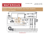
Pilot Valve - Mounted on the pump control
panel. Hydraulically controls the operation of
the relief valve.
Relief Valve - Shown mounted between discharge and
intake on a standard Waterous midship mounted pump.
Figure 1. Pilot Valve Figure 2. Relief Valve

F-1031, Section 2302.6 Page 4 of 8
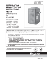
PILOT VALVE
MAIN VALVE
Figure 3. Discharge Relief Valve Operation - OFF Position
With the pump operating, water enters the main valve
from the pump discharge manifold at full discharge
pressure. It also enters the four way valve at full dis‐
charge pressure through port 1. With the four way
valve OFF, water passes through the four way valve
and out port 2 to main valve chamber B, bypassing the
pilot valve.
Valve Piston
Strainer
To Pump
Intake
Port 3
Chamber A
Pressure
Adjusting
Spring
Orifice
From
Pump
Discharge
4 Way Valve in
OFF Position
From Pump
Port 1
To Pump
Intake
Manifold
Main Valve Spring
Discharge
Manifold
In this condition, water pressure is equal on both sides
of the main valve. Since the valve diameter is greater at
the flange end of the main valve than at the seating end,
the total force applied to the flange end by water in
chamber B is also greater. This force imbalance com‐
bined with the force of the main valve spring holds the
main valve closed. The main valve remains closed, re‐
gardless of the discharge pressure.
The pilot valve is usually turned OFF only when dis‐
charge pressures above 300 psi are required, or if high‐
er pressures are desired without the necessity of dis‐
turbing the pilot valve setting.
Port 2
Chamber B

F-1031, Section 2302.6 Page 5 of 8
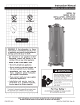
PILOT VALVE
MAIN VALVE
Figure 4. Discharge Relief Valve Operation - ON Position Main Valve Closed
Main Valve Spring
Strainer
Valve Piston
Chamber A
Orifice
4-W ay Valve in
Port 3
Pressure
Adjusting
Spring
From Pump
Port 1
Port 2
Chamber B
From
Pump
Discharge
With the pump operating, water enters the main valve
from the pump discharge manifold at full discharge
pressure. It also enters the four way valve at full
discharge pressure through port 1. With the four way
valve ON, water passes through the strainer and fills
chamber A above the valve piston. Water also passes
through the orifice, back through the four way valve and
out port 2 to the main valve chamber B.
To
Pump
Intake
To
Pump
Intake
ON Position
Discharge
Manifold
Manifold
In this condition, water pressure is equal on both
sides of the main valve. Since the valve diameter is
greater at the flange end of the main valve than at the
seating end, the total force applied to the flange end
by the water in chamber B is also greater. This force
imbalance combined with the force of the main valve
spring holds the main valve closed.
As long as pump discharge applies a load to the pilot
valve piston that is less than the compression load of
the pressure adjusting spring, the piston remains
seated, preventing discharge through port 3 back to
pump intake.

F-1031, Section 2302.6 Page 6 of 8
PILOT VALVE
MAIN VALVE
Figure 5. Discharge Relief Valve Operation - ON Position Main Valve Open
To Pump
Intake
Manifold
Valve Piston
Strainer
4 Way Valve in
To Pump
Intake
Port 3
Chamber A
Pressure
Adjusting
Spring
From Pump
Port 1
Orifice
Port 2
Chamber B
From
Pump
Discharge
When a discharge valve is closed or the engine is
accelerated, the pump discharge pressure in chamber
A may exceed the compression load of the pressure
adjusting spring. In this case the valve piston unseats
and water is allowed to escape through port 3 to the
pump intake. The orifice through which the water must
flow from the pilot valve to the main valve causes the
pressure in chamber B to be lowered. The force
exerted on the seating end of main valve now exceeds
that on the flanged end, and the valve opens. Some or
all of the discharge water now bypasses from the
discharge manifold back to the intake side of the
pump.
Manifold
Main Valve Spring
ON Position
Discharge
If the discharge pressure drops below the compression
setting on the pressure adjusting spring, the valve
piston will reseat and stop flow through port 3 allowing
pressure to build up in chamber B and reclose the
main valve. Usually the pressure drops to a level
where the pressure in chamber B increases enough to
balance discharge pressure acting on the opposite end
of the main valve, so the main valve is neither fully
open nor fully closed.

F-1031, Section 2302.6 Page 7 of 8
Operating Instructions
To adjust the system for opening pressures below 300 psi,
use the following procedure:
Note: To prevent minor pressure surges from opening
the relief valve, many pump operators set the pilot
valve about 5 psi above the intended discharge pres‐
sure
WARNING
!
Pressure Hazard. May result in personal injury.
Always reduce pressure with engine throttle to ensure
the relief valve is closed before turning the four-way
valve OFF.
1. Reduce pump discharge pressure with engine throttle.
Make sure four way valve is OFF.
2. Open at least one discharge valve. Accelerate engine
until pressure gage indicates relief valve opening
pressure.
3. Turn four way valve ON.
4. Watch pressure gage or indicating lights:
Note: Indicator lights enable the pump operator to
know at any time whether the relief valve is open or
closed. A green light is on when the relief valve is
closed, and an amber light shows when the valve is
open.
a. If gage reading drops below desired pressure
(relief valve opens), turn pilot valve handle clock‐
wise until pressure increases to desired value
(relief valve closes).
b. If gage reading does not drop, slowly turn pilot
valve handle counterclockwise until gage pres‐
sure drops about 5 or 10 psi below desired setting
(relief valve opens). Gradually turn handle clock‐
wise until gage needle is steady at desired dis‐
charge pressure (relief valve closes).
5. The relief valve will now automatically prevent dis‐
charge pressures much greater than the one for which
it is set. To readjust relief valve at a different pressure,
repeat the procedure outlined in steps 1 through 4.
WARNING
!
If the intake pressure increases greatly because of a
reduction in flow, the relief valve will not be able to
control the discharge pressure to the selected setting.
The relief valve cannot control discharge pressure to
an amount lower than intake pressure plus about 50
psi. When operating from draft or booster tank, the
relief valve may not control at discharge pressures
less than about 90 psi.
Note: When the relief valve is open, water may be
heard rushing through it at high velocity.
If discharge pressures greater than 300 psi are required,
the four way valve must be OFF. This bypasses the pilot
valve and keeps the relief valve seated, regardless of
discharge pressures. Turning the four way valve does not
disturb the pilot valve setting. To actuate the pilot valve,
turn the four way valve ON.
After Pumping
If the relief valve will be exposed to freezing temperatures,
turn the pilot valve on and open the drain cock in the relief
valve cover to drain. Some systems may have a separage
drain control for the pilot valve.
CAUTION
Failure to drain the valve in freezing weather may re‐
sult in serious damage. Failure to close the valve after
draining may cause the relief valve to stay open while
pumping.

F-1031, Section 2302.6 Page 8 of 8
Maintenance Instructions
If the relief valve operation is sluggish or erratic, the cause
can usually be traced to fine sand, grit or other foreign
material clogging one of the valves or strainer. At least
monthly, follow the exercise instructions below to ensure
proper relief valve operation.
1. Engage the pump per appropriate instructions and
increase pump discharge pressure to 150 psi.
2. With the pilot valve OFF, remove the strainer assem‐
bly. Clean the strainer and the orifice in the end of the
rod.
3. Cover stainer opening with hand and slowly turn the
pilot valve ON and OFF several times. Water should
flow from the strainer opening in the ON position and
the relief valve should open (amber light). The water
flow should stop and the relief valve should close
(green light) in the OFF position.
4. Check the strainer O-rings and replace if required;
replace the strainer assembly (hand tight only).
5. With the pilot valve OFF, turn the pressure adjustment
handle counterclockwise until it stops.
6. Slowly turn the pilot valve ON. The relief valve should
open (amber light) and pump discharge pressure
should decrease.
7. Slowly turn the pilot valve OFF. The relief valve should
close (green light) and pump discharge pressure
should rise back to 150 psi.
8. Repeat steps 6 and 7 until the system responds
quickly when turned ON and OFF.
9. Reset the pilot valve to the desired setting and de‐
crease engine speed to idle.
WARNING
!
Scalding Water Hazard. May result in serious
burns.
When operating the pump, be sure to open at least
one discharge valve slightly to prevent the pump from
overheating. If the pump runs for a few minutes com‐
pletely closed, it may heat the water enough to scald
someone when the valve is opened. Overheating can
damage the packing, seals and other pump parts. If
the apparatus builder has installed a by-pass system
or other provision designed to prevent overheating,
opening a discharge valve may be unnecessary.
Service Checks (Indicator lights)
The relief valve system should normally require minimal
attention other than the basic exercise procedure de‐
scribed on this page. If the procedure does not correct
relief valve operation, follow the instructions below.
Open relief valve drain, drain cock on the relief valve cov‐
er (if it is accessible), or unfasten the connection between
the pilot valve and relief valve (at the relief valve). If the
pressure then decreases, the relief valve is not stuck, and
the trouble can be attributed to the pilot valve. If the pres‐
sure does not decrease, however, the main valve is stuck.
If either pilot valve or relief valve is inoperable, disas‐
semble, clean and rebuild according to the instructions
provided in the repair kit for each item.
These indicating lights usually require no attention other
than routine bulb replacement. The information below is
necessary only if more extensive repairs are required, or
the valve is disassembled for any reason.
If the indicator lights do not work properly, check out the
indicating system as directed below.
1. Make sure switch is adjusted properly as directed
below.
2. Check all wiring for loose terminals, damaged insula‐
tion or broken wire strands, especially near terminals.
Make sure ground wire is firmly connected to a
mounting screw.
3. Connect a jumper wire alternately between a ground
and the harness terminals on the indicator lights to
make sure bulbs and sockets are in good order.
Replace bulbs or sockets as necessary.
4. Manually operate control switch. If lights do not oper‐
ate in sequence (amber light on when switch plunger
is depressed, and green light on when it is released),
the switch is probably defective, and should be
replaced.
If the switch is replaced or has been temporarily removed
from its mounting bracket, adjust the clearance between
the switch plunger and actuating rod so that insertion of a
0.015 inch feeler gage will light the amber indicator, but
insertion of a 0.010 inch gage will not.
/